To avoid these ads, REGISTER NOW!

Sioux Bench Grinder #2035 Wiring help (PLEASE!)

AZ_Ron

Member
Joined
Nov 23, 2014
Messages
7
Location
Idaho Falls, ID
Hi folks... I really have exhausted every resource I can find on this one, as I hate to trouble anyone, BUT... I'm at my wits end.
A few years ago, I picked up an old Sioux Model# 2035 bench grinder. I was in 'Restoration' mode, and although everything worked,
I disassembled it, media blasted and painted everything, but for some stupid reason, this one time, I took no pictures before hand, and
didn't make any notes of how the electrical was connected. I've searched high and low, and keep coming up empty. This has been sitting
for quite a while now, and I'd REALLY like to get it up and running.
I haven't been able to figure out when this thing was built, I'm guessing 1940's maybe.
My dilemma with wiring is this...
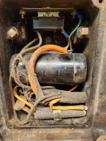
It's a 6", 1/2HP motor, with 6 cloth covered, black wires coming out the bottom... the wires come from two separate holes
in the motor... The wires have small, stamped steel bands crimped on them, numbered 1-6.
Wires 1, 2 and 3 come out of one hole, 4, 5 and 6 come from the other.
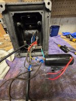
Does anyone out there have any kind of reference material, or maybe even one of these old sioux grinders that they'd be
willing to flip over and trace where the wires go?? I've been kicking myself for a very long time over not making note of how it was wired. I can't for the life
of me imagine why I didn't!!
Here are a few pics... help would be MOST appreciated!!

Thanks!

Ron
 

Attachments

  • 20220615_134934.jpg
    20220615_134934.jpg
    442.4 KB · Views: 40
  • 20220615_145538.jpg
    20220615_145538.jpg
    405 KB · Views: 42
  • 20220615_145432.jpg
    20220615_145432.jpg
    855.6 KB · Views: 44
To avoid these ads, REGISTER NOW!
OP
A

AZ_Ron

Member
Joined
Nov 23, 2014
Messages
7
Location
Idaho Falls, ID
I did a little more digging on this... pulled the end bells off, started checking the wires with a meter.
Wire #6 goes to one end of the centrifugal switch. Wires 1 & 3 show Zero Ohms, and wires 2 & 4
also show Zero ohms. Wire 5 I was unable to find any other point at which i could get any kind
of resistance. I freely admit, I'm not an AC motor guy... most of my experience has been with DC motors and Steppers.
I searched for another hour, but still didn't come up with anything that was usable (to me at least).
I know I need to wire in a cap and a switch, I just don't know which goes where.

Ron
 

1982fxr

Well-known member
Joined
Jan 7, 2012
Messages
10,003
Location
Phoenix
If you're in a city there has to be a shop of some type you could pop into right? Or do you know a good electrician..

Those Sioux grinders sure don't cone up on here much, I know that.
 

Ricky Joe

Well-known member
Joined
Sep 15, 2013
Messages
2,452
Location
Roanoke, Va.
I’ve got an old Sioux grinder. Inspire of a squirrelly switch, it is the one I use most. I’ll send pictures shortly.
 

Attachments

  • image.jpg
    image.jpg
    287.2 KB · Views: 36
  • image.jpg
    image.jpg
    195 KB · Views: 33

Maui

Well-known member
Joined
Sep 16, 2012
Messages
2,863
Location
Upstate NY
I just sold one a few weeks ago. Otherwise I would have taken a look for you. This is a general electric motor, and it lists a patent number on the motor plate. I’d suggest looking up the patent online with Google Patents to see what drawings are included with it and any description of how the wiring is supposed to be laid out.
 

bmwrd0

Well-known member
Joined
Nov 7, 2010
Messages
5,455
Location
Beaver Fever Oregon
Did it have a capacitor, or is it an induction/repulsion motor? I am going to guess the former, and if you look online there are a number of wiring diagrams for single phase motors with two run windings.

52151344712_1ec821a0f7_b.jpg
Here is a good wiring diagram of what you are most likely dealing with. You will need to determine which are the start winding and the two run windings, but it is pretty simple at that point. The two run winding will have similar Ohm ratings, while the stare winding will have a different rating. Don't forget to run a ground wire.
 
To avoid these ads, REGISTER NOW!
OP
A

AZ_Ron

Member
Joined
Nov 23, 2014
Messages
7
Location
Idaho Falls, ID
Thank you all for the responses!
I rechecked my readings, and apparently was in a hurry initially.
Wires #1 and #3 read 1.4 ohms.
Wires #2 and #4 read 1.3 ohms.
Wires #5 and #6 run through the centrifugal switch and read 3.7 ohms when the switch is closed.

I moved up to Idaho Falls from Phoenix a few years ago, and the only real thing I miss was being able to find damn near anything and everything you could want in Phoenix... IF is a MUCH smaller town, only about 60,000. I did stop at a couple of AC motor repair shops, and was basically told they couldn't help. I figured a small shop in a small farming community would for sure have some experience, but these are Grinders are odd balls to be sure.
BMWRD, I can't honestly say for sure whether it had a cap or not. Yes, I'm still kicking myself!
There are two patents listed on the motor, but neither one proved helpful in this instance.
If I'm looking at the diagram you posted correctly, I would have wires T1 and T3 as one winding and T2 and T4 as the second...
Is that correct? Also, the switch shown in the diagram, is that the centrifugal switch or an on/off switch?
I'm trying not to make assumptions, but I'm thinking it is the centrifugal switch, and that the diagram doesn't show
a power switch...

I think this gets me really close... please let me know if what I've typed above seems to be going in the right direction.

Thanks again, one and all for taking the time to help out!

Ron
 

RTM

Well-known member
Joined
May 13, 2019
Messages
13,130
Location
SF Bay Area
As it is shown inside the motor housing, I’d be inclined to think centrifugal switch is shown.
 

Davefr

Well-known member
Joined
Jan 7, 2010
Messages
11,822
Location
OR
Since the nameplate shows "CAP" then I would assume bmwrd0's image is representative of your motor and you need a cap in the base. The fact that it's single voltage and single speed suggest a one section run winding. (however it could still be a sectional run winding if that stator was used in different motors that have dual voltage or reverse). You just need to reverse engineer the wiring and test it. Brief tests won't hurt things if you're very careful. Just monitor for quick start up, and normal run current and proper direction. If the motor won't start in a couple seconds or struggles to come up to speed, then quickly turn it off! Start windings are unforgiving if energized on a non spinning motor.

Run winding ohms should be < Start winding ohms and the cap goes in series with the centrifical switch and start winding. Motor switch switches Hot, Neutral goes to other leg of power. source. Use a 3 wire cord and attach green to motor's case or ground.
 

Maui

Well-known member
Joined
Sep 16, 2012
Messages
2,863
Location
Upstate NY
Please verify the motor has been properly grounded before plugging it in to power. otherwise you may end up having a very bad day...
 
OP
A

AZ_Ron

Member
Joined
Nov 23, 2014
Messages
7
Location
Idaho Falls, ID
I LOVE you guys!!! Wired it up per the above diagram, just swapping my coil numbers for the ones in the schematic, and she fired right up!
I used a formula to calculate the start cap I needed, and it seems to work perfectly!! Thanks so much for the input one and all!!
If you're ever in Idaho Falls, message me and I'll buy the beer!
I'll toss some pics up once I get her all back together.

Ron
 

simao

New member
Joined
Jan 12, 2026
Messages
1
Hi all! I'm going to revive this thread with much the same issue as AZ-Ron. I'm reassembling a model 5BB358 which has a similar motor layout as Ron's 2035, although it's a few decades newer I believe. Anyhow, I think the schematic already posted shows what I need to do with my wiring. I've posted some pics of before and after internal wiring. I've crimped on new ring terminals and heat gun some protection on The Frayed wiring. The capacitor still works and the motor did indeed work before I started taking it apart to restore everything. The wires have their original numbering on them, so if they conform to the above schematic, things should work?

Any advice or guidance or scolding would be helpful.1446.jpg
 

Attachments

  • 20251010_163256.jpg
    20251010_163256.jpg
    1.2 MB · Views: 3
  • 20260321_182415.jpg
    20260321_182415.jpg
    1.1 MB · Views: 5
  • 20251011_110923.jpg
    20251011_110923.jpg
    1 MB · Views: 5
Last edited:
To avoid these ads, REGISTER NOW!
Top Bottom