To avoid these ads, REGISTER NOW!

Small Plate Roller Build

f150skidoo

Well-known member
Joined
Dec 29, 2012
Messages
1,206
Location
Ontario, Canada
Plate Roller Build

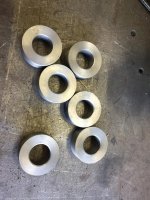
I've been getting into building custom CNC cut fire pit rings with what ever design/ wording the customer wants. The previous rings have been bump bent in my press brake. But that was very time consuming laying out all those bends and setting up the stops in the brake for repeatable bends. I have several more that I have been asked to make so I decided to build a small plate roller to roll the rings instead.

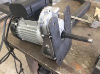
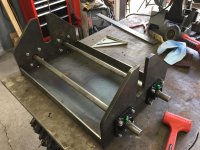
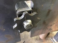
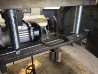
The roller will be 24" wide using the 3 roller design for simplicity. The top roller will be the pinch roller using a 8 ton bottle jack. The bottom 2 rollers are the driven rollers, I'm using a harbor freight 1320lb cable hoist that will be modified to power the rollers.

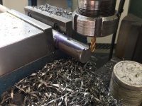
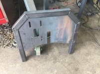
I'm trying to build the roller mostly with material I have on hand so I cut the side plates from 1/2" plate. I mag drilled the bolt holes for the flange mount bearing's since the holes were to small accurately to cut on the CNC plasma.
 

Attachments

  • IMG_0423.jpg
    IMG_0423.jpg
    150.9 KB · Views: 200
  • IMG_0426.jpg
    IMG_0426.jpg
    136.5 KB · Views: 191
  • IMG_0427.jpg
    IMG_0427.jpg
    145.8 KB · Views: 184
  • IMG_0429.jpg
    IMG_0429.jpg
    150.6 KB · Views: 195
Last edited:
To avoid these ads, REGISTER NOW!
OP
F

f150skidoo

Well-known member
Joined
Dec 29, 2012
Messages
1,206
Location
Ontario, Canada
Before I got to far ahead of myself I wanted to temporarily mount the bearings and throw a piece of cold rolled shaft in to check that the bearing are mounted in the correct spots and turning true. I checked the shaft with my dial indicator and they are turning with in .005". Next I made the mount for the HF cable hoist out of 1/4" plate. The legs consist of 2'x2" tubing and 1/4" plate for the lower frame, I slotted the plate so I can tension the chain from the motors weight. The slot in the lower center will guide a rectangle tube, which will transfer the cylinders force via 1/2" flat bar to move the top roller.
 

Attachments

  • IMG_0436.jpg
    IMG_0436.jpg
    144.6 KB · Views: 248
  • IMG_0435.jpg
    IMG_0435.jpg
    105.6 KB · Views: 201
  • IMG_0433.jpg
    IMG_0433.jpg
    150.5 KB · Views: 209
  • IMG_0432.jpg
    IMG_0432.jpg
    150.9 KB · Views: 203
  • IMG_0431.jpg
    IMG_0431.jpg
    144.9 KB · Views: 199
  • IMG_0430.jpg
    IMG_0430.jpg
    151.9 KB · Views: 218
OP
F

f150skidoo

Well-known member
Joined
Dec 29, 2012
Messages
1,206
Location
Ontario, Canada
Most of what Ill be bending is 12" of 3/16" but I think i should be able to bend full width of 3/16". The rollers are going to be 4" 3/8" or 1/2" wall DOM tubing so they should be stiff enough to roll that thickness of steel.
 

mohead1

Member
Joined
Apr 10, 2013
Messages
8
Re: Plate Roller Build

Thing is large and how heavy?? 200lbs w motor??

Sent from my SM-G900V using Tapatalk
 
OP
F

f150skidoo

Well-known member
Joined
Dec 29, 2012
Messages
1,206
Location
Ontario, Canada
I'm guessing this machine will weigh in the 300-400 lb range all said and done. I originally thought of making a small manual roller that you could pickup and store under the welding table. But that quickly morphed into what you see now.
 

PugetDude

ALLIANCE MEMBER
Joined
Mar 13, 2013
Messages
22,263
Location
Superstition Mountains, AZ
Are you going to pre-bend the ends of the rings to your desired radius before rolling or incorporate a swing-away top roll support so you can tack weld and then re-roll for concentricity?
If you don't you'll be welding two flat spots together and end up with pear-shaped fire rings.
If you don't have a swing-away outboard top roll support, another option is to tack weld while still in the roller, re-roll, then cut the tacks. remove the ring and then finish weld.
 
To avoid these ads, REGISTER NOW!
OP
F

f150skidoo

Well-known member
Joined
Dec 29, 2012
Messages
1,206
Location
Ontario, Canada
Got some more progress completed today for the downward motion of the top roller. I used some 1.5" x 2.5" .188 wall tubing which will transfer the force from the 8 ton bottle jack to the flat bars which will lower the top roller. I will add a stiffener to the rectangle tubing to help with the deflection. I threaded some bar stock and welded it to the inside of the tube and cut a hand knob so I can remove the tension bars/ top roller with no tools. I cut the tension bars out of 1/2" plate and welded a 1/4" plate spacer. The spacer slides over the 1.5x2.5 tube and transfers the force instead of the 1/2" bolt on the hand knob. I needed to add a spacer between the unsupported parts of the legs to add rigidity. I could of used angle iron or small square tubing but that's to simple. So I cut and bent up some 11 ga. steel with the same radius as the 1/4" plate sides. Keeping with the hexagon theme on the tension bars I cut a honeycomb to help with air flow from the motor.
 

Attachments

  • IMG_0449.jpg
    IMG_0449.jpg
    128.6 KB · Views: 141
  • IMG_0448.jpg
    IMG_0448.jpg
    150.1 KB · Views: 155
  • IMG_0445.jpg
    IMG_0445.jpg
    112.4 KB · Views: 146
  • IMG_0443.jpg
    IMG_0443.jpg
    103.3 KB · Views: 148
  • IMG_0440.jpg
    IMG_0440.jpg
    125.1 KB · Views: 157
  • IMG_0439.jpg
    IMG_0439.jpg
    149.6 KB · Views: 161
OP
F

f150skidoo

Well-known member
Joined
Dec 29, 2012
Messages
1,206
Location
Ontario, Canada
I didn't get much done in the shop today, but I got the front panel cut out and bent. I need to make a longer jack handle to fit through the slot in the front panel but its 20mm and 3/4" is just to loose of a fit. So Ill I have to come up with some kind of solution.
 

Attachments

  • IMG_0452.jpg
    IMG_0452.jpg
    132.2 KB · Views: 138

matt_i

Well-known member
Joined
Mar 14, 2008
Messages
10,720
Location
SE Michigan
Very cool use of the plasma table :thumbup: looking forward to seeing the progress! You will have a moneymaker there when you get done :)
 
OP
F

f150skidoo

Well-known member
Joined
Dec 29, 2012
Messages
1,206
Location
Ontario, Canada
So a bit of a update, I ended up using 3" x .500" wall DOM instead of 4" DOM for the rollers due to availability and cost. I had a local retired machinist turn me some spacers that fit in the ID of the DOM to keep the roller concentric to the shaft, (need to get a lathe for myself). I milled the key ways to connect the gears to the roller shafts. The roller's are connected to the motor with #40 roller chain with a 2:1 reduction to decrease the roller's RPM. I did a quick test with some 3" x 3/16" flat bar and was happy with the result, but realized a issue with the machine. Since it was designed with 4" rollers but now uses 3" they don't pinch enough to make a circle smaller then a 22" diameter. To resolve the issue I'm going to have to cut the notches in the side plate down to make the top roller have more travel. This project is going to have to be put on the back burner for a bit since I won't have time to work on it for several weeks.
 

Attachments

  • IMG_0453.jpg
    IMG_0453.jpg
    132.9 KB · Views: 91
  • IMG_0462.jpg
    IMG_0462.jpg
    153.4 KB · Views: 113
  • IMG_0464.jpg
    IMG_0464.jpg
    149.6 KB · Views: 127
  • IMG_0465.jpg
    IMG_0465.jpg
    112.4 KB · Views: 118

dkmc

Well-known member
Joined
Jan 20, 2008
Messages
948
Location
NYS--Upstate in the corn fields
I really enjoy seeing HF tools repurposed for different uses. The hoist motor is ideal for this and other applications and it's low cost for what it's accomplishing. Great project.
 
To avoid these ads, REGISTER NOW!
Top Bottom