I recently started using a garage that had a snap on compressor that does not work I took the side panel of and the wiring is not good to say the least. It’s a single phase motor does anyone know how I could get it working. The wiring it already ran from the breaker box.

You are using an out of date browser. It may not display this or other websites correctly.
You should upgrade or use an alternative browser.
You should upgrade or use an alternative browser.
Snap on compressor
- Thread starter Zlove304
- Start date
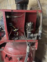


theres been a lot of tampering in there.
I would start by determining the motor voltage and wiring it direct ( bypassing the pressure switch and everything) to see if it runs. but 'first, see if everything turns by hand and no clunks or clanks etc .
once you determine that it pumps pressure , holds air, etc, you can work with the rest .
It looks like it has an hour meter? and an on/off switch on that case.
I would start by determining the motor voltage and wiring it direct ( bypassing the pressure switch and everything) to see if it runs. but 'first, see if everything turns by hand and no clunks or clanks etc .
once you determine that it pumps pressure , holds air, etc, you can work with the rest .
It looks like it has an hour meter? and an on/off switch on that case.
It does have a on/off and hour.theres been a lot of tampering in there.
I would start by determining the motor voltage and wiring it direct ( bypassing the pressure switch and everything) to see if it runs. but 'first, see if everything turns by hand and no clunks or clanks etc .
once you determine that it pumps pressure , holds air, etc, you can work with the rest .
It looks like it has an hour meter? and an on/off switch on that case.
how would I go about by passing the pressure switch ?
take the wires that go to the motor, and basically "plug them in" but you first need to be sure the pump & motor spin freely, and also determine the volage & amp draw of the motor. can you snap a pic of the motor plate
is that the wiring on the motor? has that been messed with too? show some pics
Model istake the wires that go to the motor, and basically "plug them in" but you first need to be sure the pump & motor spin freely, and also determine the volage & amp draw of the motor. can you snap a pic of the motor plate

what is the voltage and amp draw etc on the motor. is there a plate on the motor with that info? it will have horse;power, rpm, etc
are those yellow wires comming straight from the motor?
are those yellow wires comming straight from the motor?
yes, pretty sure you will need more pics. I'm wondering if its a 3 phase motor you have . ( edit, you already said single phase )
maybe someone with more motor experience will chime in , but I'm sure you need more info .
maybe someone with more motor experience will chime in , but I'm sure you need more info .
Last edited:
wyliesdiesels
Well-known member
First step is posting a pic of the motor nameplate.
TRWham
Well-known member
Looks to me like the contactor is missing. Perhaps it failed and was removed but never replaced.
The yellow wires that are taped together need to stay together. It's just line 1 and line 2. Wire nut a cord to it and see what happens.
It's definitely missing the contactor (starter). Don't wire the motor straight to the pressure switch. That pressure switch will probably not handle the motor current.
I can pretty much tell what wires need to go where when you end up putting the contactor back in. Let me know if you need help.
If you tell us the horsepower we can tell you what contactor it needs.
It's definitely missing the contactor (starter). Don't wire the motor straight to the pressure switch. That pressure switch will probably not handle the motor current.
I can pretty much tell what wires need to go where when you end up putting the contactor back in. Let me know if you need help.
If you tell us the horsepower we can tell you what contactor it needs.
Last edited:
Be careful about wiring the motor directly. Remove the belts and be careful about sparks.
As others mentioned, pictures/info about the motor would be very helpful. Also, what are the objectives here? Are you busy looking to get it running or to restore what ever the factory setup was?
If this is a lower power compressor (under say 18A) you could look at ripping virtually all that stuff off and just getting a decent pressure switch (Condor or Square D for example), connect the motor to one side and wall power to the other. Set the pressure and you are done. Most lower power compressor have motors with internal thermal protection (look for a reset button). They don't need a magnetic starter.
If that is a ~5hp model then it probably wants a mag starter. If the motor has a reset then you only need the starter. If it doesn't then you need a starter with overload. You can just bypass all the original stuff if you want.
Looking at the picture my guess is this system had a mag starter but it's hard to tell. Searching the model # turned up nothing.
As others mentioned, pictures/info about the motor would be very helpful. Also, what are the objectives here? Are you busy looking to get it running or to restore what ever the factory setup was?
If this is a lower power compressor (under say 18A) you could look at ripping virtually all that stuff off and just getting a decent pressure switch (Condor or Square D for example), connect the motor to one side and wall power to the other. Set the pressure and you are done. Most lower power compressor have motors with internal thermal protection (look for a reset button). They don't need a magnetic starter.
If that is a ~5hp model then it probably wants a mag starter. If the motor has a reset then you only need the starter. If it doesn't then you need a starter with overload. You can just bypass all the original stuff if you want.
Looking at the picture my guess is this system had a mag starter but it's hard to tell. Searching the model # turned up nothing.
BillK
Well-known member
There should be a Snap On model number on it somewhere. I have found it very easy to get manuals from Snap On. They will usually send you a PDF copy. Otherwise I guess you can put some pictures of the motor plate etc and try to figure it out.
wyliesdiesels
Well-known member
Its not that the motor wants a mag starter. that makes no sense. its that pressure switches arent rated for the higher currents of larger motors.Be careful about wiring the motor directly. Remove the belts and be careful about sparks.
As others mentioned, pictures/info about the motor would be very helpful. Also, what are the objectives here? Are you busy looking to get it running or to restore what ever the factory setup was?
If this is a lower power compressor (under say 18A) you could look at ripping virtually all that stuff off and just getting a decent pressure switch (Condor or Square D for example), connect the motor to one side and wall power to the other. Set the pressure and you are done. Most lower power compressor have motors with internal thermal protection (look for a reset button). They don't need a magnetic starter.
If that is a ~5hp model then it probably wants a mag starter. If the motor has a reset then you only need the starter. If it doesn't then you need a starter with overload. You can just bypass all the original stuff if you want.
Looking at the picture my guess is this system had a mag starter but it's hard to tell. Searching the model # turned up nothing.
I doubt a 5HP motor would have integral overloads...
The key word in that sentence is "it". I admit, "it" could be read as "the motor" but in my case I meant "it" to mean the compressor as a system. You are correct, the motor itself doesn't care if the pressure switch or a mag starter is making/breaking the circuit. From what I've observed, under 5hp is almost always directly switched and over 5hp use starters but those rated at 5hp seem to be either or depending on price/quality.Its not that the motor wants a mag starter. that makes no sense. its that pressure switches arent rated for the higher currents of larger motors.
I doubt a 5HP motor would have integral overloads...
As for 5hp with integral overload, low cost models that use the pressure switch need the integrated thermal protection since the mag starter can't provide the protection externally. Thus lower cost 5hp models are where I've seen it. For example, I think this is the same IR I've been helping a friend with.
https://www.tractorsupply.com/tsc/product/ingersoll-rand-80-gallon-5-hp-reciprocating-air-compressor
The motor plate says 5hp, 22 or 23 Amps. It has a thermal reset on the motor (see the picture). Same with this IR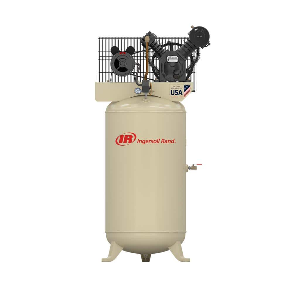
Ingersoll Rand Type 30 Reciprocating 80 Gal. 5 HP Electric 230-Volt, Single Phase Air Compressor 2340N5-V - The Home Depot
Ingersoll Rand Stationary Compressor is intended to provide both reliability and performance in heavy shop or industrial applications.
www.homedepot.com
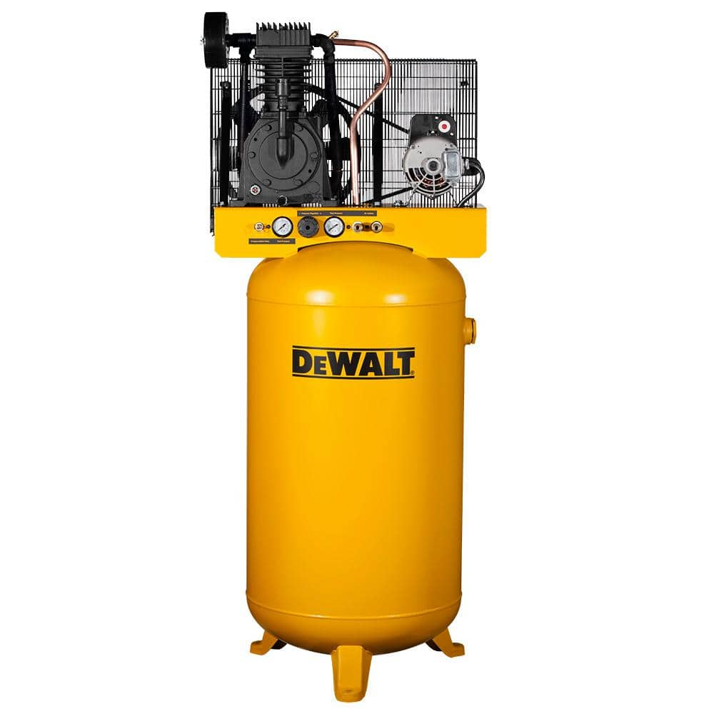
DEWALT 80 Gal. Stationary Electric Air Compressor DXCMV5048055 - The Home Depot
Provide a longer run time for air tools such as ratchets, impact drivers in jobsite with this Stationary Electric Air Compressor from DEWALT.
www.homedepot.com
I'm not going to claim that's a good idea, only that some compressors are sold that way.

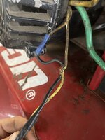


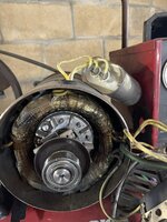

It looks like the thin wires went to the hob meter. The thick wires were motor power. In addition to any wire and connectors that might be needed, you need a new motor starter with a thermal overload. You also probably need a new pressure switch. The pressure switch should be under $30, the starter probably around $100-200 depending on model and options. If you get a pressure switch with an "0ff-auto" Just as examples (I didn't search by pressure range or anything like that) here are two square D models, one without an off-auto switch
https://www.grainger.com/product/2FG90
and the other with
https://www.grainger.com/product/3AY90
Here is a low cost magnetic starter with overload protection
https://www.amazon.com/Magnetic-Motor-Starter-General-Electric/dp/B0080HE0U6
You probably can use the old power (off-auto) switch on the front panel but it might be easiest to simply bypass it and use one on the pressure switch.
https://www.grainger.com/product/2FG90
and the other with
https://www.grainger.com/product/3AY90
Here is a low cost magnetic starter with overload protection
https://www.amazon.com/Magnetic-Motor-Starter-General-Electric/dp/B0080HE0U6
You probably can use the old power (off-auto) switch on the front panel but it might be easiest to simply bypass it and use one on the pressure switch.
How do I have it working two hot wires to the pair of yellow. How would I wire the on off switch and pressure switch. The on off is a 3 prong and the pressure switch has 2 lines in hot and negative and two lines out hot and negative but I have 2 hot wires in not sure what to do there
to me, the picture of the windings look like they have got hot & black ( 10 0clock & 2 Oclock)
the windings at 10 oclock look like they've been hammered on
the windings at 10 oclock look like they've been hammered on
Last edited:
It's hard to say but I do see the black area. This is why the motor needs to be hooked up and ran on a cord before any money is spent on parts.to me, the picture of the windings look like they have got hot & black ( 10 0clock & 2 Oclock)
the windings at 10 oclock look like they've been hammered on
the black on the windings @10 O'clock may be from the centrifugal contact as it looks burned also. I think it would match that spot if the cover is back on. I had to replace that contact p[late on the motor on my compressor when I got it. Still worked but while I was in there, it was replaced along with the bearings .
Can you take a picture of how you wired things up? The auto-off switch is *probably* just in line with the pressure switch wires. That is the wire that switches the motor starter on/off goes from the starter to the pressure switch, then to the off/auto switch then back to the starter. However, that assumes that switch is a 240V rated switch (I'm assuming the pressure switch line is 240V).
great that you got the motor running!
