To avoid these ads, REGISTER NOW!

Solidworks Question: Pyramidal Hopper & Loft Tool

mikew13

Well-known member
Joined
Jun 25, 2011
Messages
513
Location
USA
So if I create a pyramidal hopper using the loft tool in Solidworks, is there a way to explode it into four panels that I can turn into dxf files for each of the four panels? As in separating four sides.
its way too big to do it by sheetmetal so each of the four sections has to be welded together with angled panels.
 

Attachments

  • 36in. Hopper.JPG
    36in. Hopper.JPG
    138.4 KB · Views: 44
To avoid these ads, REGISTER NOW!

RoninB4

Well-known member
Joined
Jul 22, 2020
Messages
3,479
Location
Under My House
So why not create 4 panels in SWX and make an assembly from them? Make the panel models (CAD) the same way you would in reality. The hem/overlap you'd use for welding could be modeled in the Sheet Metal module and then obtain a Flat Pattern for layout. Why are you doing something in SWX differently than in reality? Just a suggestion.
 
OP
M

mikew13

Well-known member
Joined
Jun 25, 2011
Messages
513
Location
USA
So why not create 4 panels in SWX and make an assembly from them? Make the panel models (CAD) the same way you would in reality. The hem/overlap you'd use for welding could be modeled in the Sheet Metal module and then obtain a Flat Pattern for layout. Why are you doing something in SWX differently than in reality? Just a suggestion.
It is different when you are dealing with a pyramid instead of two angled sides.
 

RoninB4

Well-known member
Joined
Jul 22, 2020
Messages
3,479
Location
Under My House
It is different when you are dealing with a pyramid instead of two angled sides.
-What's so different? A flat tapering panel with a corresponding bevel/hem/overlap for fitment. You've already got the dimensions in your one feature (two sketches) model so take the dimensions you already have and create individual panels you load into an assembly model. What don't I understand?
 

RoninB4

Well-known member
Joined
Jul 22, 2020
Messages
3,479
Location
Under My House
Here's a quick assembly with 4 identical panels I just did. They can be different or all the same. All are sheet metal. This took all of 17 minutes to do.

Hopper.JPG
 
Last edited:

RoninB4

Well-known member
Joined
Jul 22, 2020
Messages
3,479
Location
Under My House
I suppose you could even use just the single model you've created with the configuration manager (cutting three sides at a time) and making a dxf out of each configurations (2 or 4) but that would be the long way around it.
 

VR6ix

Well-known member
Joined
Mar 24, 2013
Messages
355
Location
Onterrible, Canuckistan
I have done similar jobs but with more bends/flanges... 3D sketch the layout as line work, drop it into an assembly then model the panels and use the sketch to mate them and adjust your open corners & bends/flanges etc for welding. dr_clyde is right if all you need is a generic DXF file. At work we prefer to feed 3D parts into our forming software which is when the 3D sketch method helps, more so when things are not symmetrical or have other funky features going on.

There's undoubtedly a ton of Solidworks sheetmetal experience on here when needed 🍺
 

RoninB4

Well-known member
Joined
Jul 22, 2020
Messages
3,479
Location
Under My House
mikew13, to make your solid into a model body sheet metal part you can follow this

-I don't get to fool with the sheet metal module as much as I'd like to, I'm going to have to try this on my version (2014) to see what happens.

Since the OP didn't detail how the panels would be welded together I did the simplest construction possible, flanges could be easily added for a Flat Pattern if needed.

To the OP- There's been several good options in this thread so pick something that works for your design. If you have questions there's plenty of help here on the board.
 

stuntman

Member
Joined
Oct 4, 2009
Messages
22
-I don't get to fool with the sheet metal module as much as I'd like to, I'm going to have to try this on my version (2014) to see what happens.

Since the OP didn't detail how the panels would be welded together I did the simplest construction possible, flanges could be easily added for a Flat Pattern if needed.

To the OP- There's been several good options in this thread so pick something that works for your design. If you have questions there's plenty of help here on the board.
Dermis and feline can be divorced by innumerable methods.

Best of luck OP!
 

Blt2Lst

Well-known member
Joined
Jul 9, 2015
Messages
719
Location
SoCali
Normally you can just right click a face and select export as .dxf

You shouldn’t need to convert it to sheet metal if all you need is a .dxf of the perimeter.
I am running Inventor but that's how I would do this, should also be able to do it that way in SW.
 

RoninB4

Well-known member
Joined
Jul 22, 2020
Messages
3,479
Location
Under My House
Normally you can just right click a face and select export as .dxf

You shouldn’t need to convert it to sheet metal if all you need is a .dxf of the perimeter.
-I tried this and like it for a simple perimeter shape. If a flange is required for additional wrap-around support at the corner then the Flat Pattern will likely be required. Several ways to accomplish this depending upon what is needed. Where has the OP gone?
 
To avoid these ads, REGISTER NOW!
OP
M

mikew13

Well-known member
Joined
Jun 25, 2011
Messages
513
Location
USA
Here's a quick assembly with 4 identical panels I just did. They can be different or all the same. All are sheet metal. This took all of 17 minutes to do.

Hopper.JPG
Heres the problem, I have two different sizes, the four panels aren't equal, one is 204" long, 140.625" at the bottom with a vertical depth of 59-3/4" and diagonal length of 67-5/8" on both diagonal sides and the other panel is 118.0625 at top, and 30" at bottom with a vertical depth of 51.3125" and diagonal length of 67.625" on both diagonal sides. I tried using planes but they came out different in the assembly. I am trying to figure this out. Two of each completes four panels.
 

brent769

New member
Joined
Jul 24, 2015
Messages
4
I use Inventor, and like others have said above, SW should be similar. Right click the face you want and export it as a dxf.
1675707671411.png
 

RoninB4

Well-known member
Joined
Jul 22, 2020
Messages
3,479
Location
Under My House
Heres the problem, I have two different sizes, the four panels aren't equal, one is 204" long, 140.625" at the bottom with a vertical depth of 59-3/4" and diagonal length of 67-5/8" on both diagonal sides and the other panel is 118.0625 at top, and 30" at bottom with a vertical depth of 51.3125" and diagonal length of 67.625" on both diagonal sides. I tried using planes but they came out different in the assembly. I am trying to figure this out. Two of each completes four panels.
Hi Mike, nice to see you here again. Although my example was one size of panel for all 4 of them different sizes shouldn't be much different. Is the problem in modeling the individual panels or in the assembly? You appear to have the dimensions you want so when you assemble the panels does the assembly not have the proper dimensions? Are the assembly constraints not working the way you want them to? If everything is constrained properly AND looks like you want them to BUT not having the correct dimensions (vertical depth, width, angle, etc.) then perhaps your panels aren't correct.

I'll likely work a model up using your numbers but do explain what difficulty you're having so I can give a better reply.
 
OP
M

mikew13

Well-known member
Joined
Jun 25, 2011
Messages
513
Location
USA
Tried to use planes but had to adjust the angle on each side, I would like to get an flush fit where the inner edges meet each other to be filled in with weld.
 

Attachments

  • test hopper assembly.JPG
    test hopper assembly.JPG
    153.2 KB · Views: 17

RoninB4

Well-known member
Joined
Jul 22, 2020
Messages
3,479
Location
Under My House
Tried to use planes but had to adjust the angle on each side, I would like to get an flush fit where the inner edges meet each other to be filled in with weld.
-Tried to use planes for what? For individual panels that were in an assembly model or was this a single part model creation? Notice the feature tree in the example I did, those are all individual panels brought into the assembly and attached to each other with constraints. Can you explain what you did better? How about a close up screen shot of what/where the problem is? I understand that the inner edges aren't meeting but I don't know how you've created this and a JPG at that distance isn't enough information. If the inner seams aren't flush then how big is the measured gap? Do you know how to measure the gap? How long have you been using SWX?

How you drew this AND how you modeled it AND what type of model (part vs. assembly) is important. Did you do this in the sheet metal module or is it just basic solid modeling? How thick are the panels? If the panels are fairly thick (1/8" or more) then you're also going to have an open seam on the outside like you would in reality. Not beating up on you here, I need more information to know what's gone wrong.
 
Last edited:

manac

Active member
Joined
Oct 8, 2020
Messages
44
Location
CT
A way to do this is with split part.
Add reference planes where you want to cut.
Insert, feature, split part.
I think you could do this with two cuts.
 

RoninB4

Well-known member
Joined
Jul 22, 2020
Messages
3,479
Location
Under My House
Heres the problem, I have two different sizes, the four panels aren't equal, one is 204" long, 140.625" at the bottom with a vertical depth of 59-3/4" and diagonal length of 67-5/8" on both diagonal sides and the other panel is 118.0625 at top, and 30" at bottom with a vertical depth of 51.3125" and diagonal length of 67.625" on both diagonal sides.
-Not really following your dimension scheme but I can see, by the numbers, that this is large. This isn't for around the house or farm is it? Looks like it's for your place of employment. May I ask what you do there and why you're modeling this hopper? If you'd rather not answer this where everybody can read it you can send me a private message. I won't be judgmental.
 

VR6ix

Well-known member
Joined
Mar 24, 2013
Messages
355
Location
Onterrible, Canuckistan
Heres the problem, I have two different sizes, the four panels aren't equal...
What sheet size are you working with, and is this done on a shear where the full size is usable or on a laser where there's a margin of scrap?

I might take a run at this later... dogo needs a walko first

My go to is CAD, Cardboard Assisted Design.
It's incredibly versatile! I have turned many cartoon scribbles, cocktail napkin sketches and CAD templates into workable parts in my years 🤪
 

dr_clyde

Well-known member
Joined
Jan 7, 2009
Messages
6,425
Location
Holland, MI
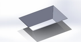
If I'm reading you correctly, I think there are a couple different ways to skin this cat. It sounds like you want flat panel .dxf drawings to cut the flats for each side. The part is too big to form from one sheet, so you need to cut each piece separately and weld them up.

The easiest way to me would be to cut an extruded boss that represents the inside negative of the shape you want. Think of this like the inside of a present, and your sheet metal will be the wrapping paper. Start with a simple extruded rectangle, then make cuts on the sides using the extruded cut tool. Draw the boss sketch on the top plane, extrude up, and then take cuts from whatever planes you need to make your shape.

Once you have the shape you can either shell it or simply export the side shapes as a .dxf. You can then take the .dxfs and create 4 individual flat parts and mate them in an assembly.

If you need me to help send me a dimensioned sketch and I can take a crack at drawing it for you.
 
To avoid these ads, REGISTER NOW!
Top Bottom