Provincial
Well-known member
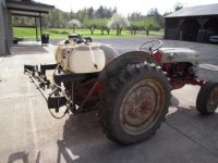
I have a 25 gallon spot sprayer setup with a folding boom that goes on my 4-wheeler. I decided to make a mount to use it on my 2N or early 8N. The height is determined by the height of the rear rack on the 4-wheeler (a Yamaha Big Bear) so that I don't have to change the boom height when switching between machines. The rack is 36" above ground level.
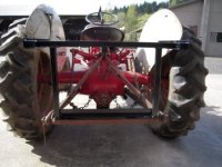
I decided to use the stock drawbar and stay braces to get a stable set of mounting points. I had some 1-1/4" square tubing pieces lying around, so I used that for most of the structure. The only new materials are the pieces of 2x2x1/8 angle iron and a small piece of 1/4x2 flat bar for the front bracket.
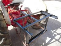
I started by cutting a piece of the angle to 25" long and drilling two 3/4" holes, each 10" from the centerline. I cut up an old 3/4" bolt into 3" sections, pointed one end, and cross-drilled for a 1/4" lynch pin. I then welded these into the hole in the angle iron, using a couple of washers above the lynch pin to give plenty of room. I later found that the lynch pins are not needed, since the geometry of the rack prevents the pins from lifting out of the drawbar.
I then cut two pieces of the angle iron to make the side rails. These are a little long toward the rear in order to provide a support to support the weight of the boom assembly when the tank is empty. Otherwise, the tank isn't heavy enough to keep the unit from wanting to tip toward the rear. I welded two pieces of square tube between the angle iron rails, one at the front and the other ten inches to the rear (directly over the drawbar), these providing a place to tie down the tank using cargo straps, as well as spacing the angles the proper distance apart. I welded a small piece of the square tubing at the rear end of the angle iron (9" behind the center cross-bar) to support the subframe of the sprayer, and provide a positive stop where the boom support sticks down. The side angle iron pieces stick up about 3/4" providing limits to side movement of the sprayer subframe. Two uprights of square tubing were welded to the bottom angle iron at the ends and to the center cross-bar on the top.
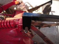
I used another piece of the square tubing to link my frame to the top link pin on the 3-point hitch. I drilled a 3/4" hole in the 1/4x2 flat bar, radiused the end, and welded it to the square tube. A lynch pin keeps the hitch pin from moving. This is the only place I am thinking of changing the design. I think I will make an open-ended saddle to drop over the pin (retained by a PTO pin through cross holes below the hitch pin to keep it from bouncing out of engagement. This will allow easier installation and removal since I can have the hitch pin fully installed before placing the locating pins in the drawbar and rotating the assembly onto the upper hitch pin.
Here is a link to my Photobucket Album if you want to view full size versions of these photos.
I decided to use the stock drawbar and stay braces to get a stable set of mounting points. I had some 1-1/4" square tubing pieces lying around, so I used that for most of the structure. The only new materials are the pieces of 2x2x1/8 angle iron and a small piece of 1/4x2 flat bar for the front bracket.
I started by cutting a piece of the angle to 25" long and drilling two 3/4" holes, each 10" from the centerline. I cut up an old 3/4" bolt into 3" sections, pointed one end, and cross-drilled for a 1/4" lynch pin. I then welded these into the hole in the angle iron, using a couple of washers above the lynch pin to give plenty of room. I later found that the lynch pins are not needed, since the geometry of the rack prevents the pins from lifting out of the drawbar.
I then cut two pieces of the angle iron to make the side rails. These are a little long toward the rear in order to provide a support to support the weight of the boom assembly when the tank is empty. Otherwise, the tank isn't heavy enough to keep the unit from wanting to tip toward the rear. I welded two pieces of square tube between the angle iron rails, one at the front and the other ten inches to the rear (directly over the drawbar), these providing a place to tie down the tank using cargo straps, as well as spacing the angles the proper distance apart. I welded a small piece of the square tubing at the rear end of the angle iron (9" behind the center cross-bar) to support the subframe of the sprayer, and provide a positive stop where the boom support sticks down. The side angle iron pieces stick up about 3/4" providing limits to side movement of the sprayer subframe. Two uprights of square tubing were welded to the bottom angle iron at the ends and to the center cross-bar on the top.
I used another piece of the square tubing to link my frame to the top link pin on the 3-point hitch. I drilled a 3/4" hole in the 1/4x2 flat bar, radiused the end, and welded it to the square tube. A lynch pin keeps the hitch pin from moving. This is the only place I am thinking of changing the design. I think I will make an open-ended saddle to drop over the pin (retained by a PTO pin through cross holes below the hitch pin to keep it from bouncing out of engagement. This will allow easier installation and removal since I can have the hitch pin fully installed before placing the locating pins in the drawbar and rotating the assembly onto the upper hitch pin.
Here is a link to my Photobucket Album if you want to view full size versions of these photos.