To avoid these ads, REGISTER NOW!

Square tubing strength question

fordnut85

Well-known member
Joined
Sep 6, 2012
Messages
231
First off, this is my first post, I have been trolling for quite awhile now and have gotten a load of great information and ideas along with drooling over some of the projects and shops.

I own an auto repair shop and have struggled to find a quality engine support bar (transverse bar). For those of you unfamiliar this is a bar that supports and engine from the top side while dropping the sub frame or transmission out of the bottom. Anyways, all the ones I have purchased or used didn't have the adjust ability that I need so I decided to build my own. Problem is I don't know how big or heavy the square tubing needs to be to support the weight. I am guessing that 2"x 2" square tubing with 1/4" wall will hold but I know there is someone here that can tell me for sure. In the most extreme of circumstances there will be a load of 1000 lbs in the center of a 60" span. Considering I'm the one standing under the thing with 1000 lbs over my head :scared: I am defiantly using the rule of 5/3rds so I need the thing to hold about 1700 lbs.

If anyone knows of a chart with the info I need I would be greatly appreciative.

Thanks
Duane
 
To avoid these ads, REGISTER NOW!
OP
F

fordnut85

Well-known member
Joined
Sep 6, 2012
Messages
231
I would say that is more than strong enough. Have you tried the OTC one? It works very well.

Yeah I have the stinger but I had an 05 VW Passat in the shop this week and it just wouldn't set where I needed it since the repair I was doing required removal of the front clip. What I have drawn up is much more modular in design and will convert from a cross bar to a 3 point setup with a bunch of adjustment.
 

AndyA

Well-known member
Joined
May 23, 2011
Messages
514
Location
Texas Near Dallas
Disclaimer: I'm not a mechanical/civil/structrual engineer. I've learned some things over the years doing projects on my own. Use this information at your own risk.

Let's round that up to 2000lbs. 60 inches = 5 ft. So for a point load with unconstrained ends the moment is 0.25 * lbs * length = 2.5 kip-ft. From the AISC steel construction book, the tables on HSS 2"x2"x1/4" shows 2.21 kip-ft for ASD and 3.33 kip-ft for LRFD (these are just two different design rules).

This says if your using ASD rules, the 2"x2"x1/4" tube is NOT acceptable. The 2.5 kip-ft moment exceeds the 2.21 kip-ft the tube can provided. LRFD design says it's acceptable. Personally I use the more conservative ASD rules. For a small project like this, the extra cost of materials is minimal.

Another look in the tables and I find a 3"x3"x1/4" tube has 5.69 kip-ft for the ASD value. 2.25"x2.25"x1/4" has a value of 2.93 kip-ft. 2.5"x2.5"x1/4" has a value of 3.75 kip-ft. Any of these should work fine, but the 3"x3" may be easier to find.

Again, you want someone else to check my math and understanding of how to design stuff like this. I have had no formal training.
 
OP
F

fordnut85

Well-known member
Joined
Sep 6, 2012
Messages
231
Disclaimer: I'm not a mechanical/civil/structrual engineer. I've learned some things over the years doing projects on my own. Use this information at your own risk.

Let's round that up to 2000lbs. 60 inches = 5 ft. So for a point load with unconstrained ends the moment is 0.25 * lbs * length = 2.5 kip-ft. From the AISC steel construction book, the tables on HSS 2"x2"x1/4" shows 2.21 kip-ft for ASD and 3.33 kip-ft for LRFD (these are just two different design rules).

This says if your using ASD rules, the 2"x2"x1/4" tube is NOT acceptable. The 2.5 kip-ft moment exceeds the 2.21 kip-ft the tube can provided. LRFD design says it's acceptable. Personally I use the more conservative ASD rules. For a small project like this, the extra cost of materials is minimal.

Another look in the tables and I find a 3"x3"x1/4" tube has 5.69 kip-ft for the ASD value. 2.25"x2.25"x1/4" has a value of 2.93 kip-ft. 2.5"x2.5"x1/4" has a value of 3.75 kip-ft. Any of these should work fine, but the 3"x3" may be easier to find.

Again, you want someone else to check my math and understanding of how to design stuff like this. I have had no formal training.

Wow thanks for all the info. In the interest of keeping weight down, where would a 2" x 4" rectangular tube stood on edge would get me??
 

zkling

Well-known member
Joined
Jan 23, 2007
Messages
16,939
Please note this is not legal advice, just using what I learned in engineering school and at work.

Can you post a diagram of the "beam" and how it will be loaded AND restrained.

I ran a quick calc....

Say you have a 2"x2" with 0.25" wall thickness. It is 60" long and simply supported at each end (not clamped, just resting on something). With a 1000lbf load at the center it will have a deflection of 0.165" at the center and a max stress value of 33000psi.

SO if you use 1020 steel that is hot rolled which has a yield strength of ~30000psi, it would take a "set". If you used some cold drawn which has a yield of ~50000psi, you would be fine.

As another member mentioned, it is better to add height in the direction that the beam is bending. Same reason why floor joist are stood on their 2" edge and I beams are loaded on their flat faces. It increases their area moment of inertia.

If you can provide a drawing, we could look at this closer.

One thing to keep in mind with tubing. It is USUALLY more beneficial to increase the square size than it is to increase the wall thickness.
 
Last edited:

AndyA

Well-known member
Joined
May 23, 2011
Messages
514
Location
Texas Near Dallas
4"x2"x1/4" has a ASD rules value of 6.74 kip-ft on the strong axis and 4.10 kip-ft on the weak axis. It's stronger in the 2" direction than the 2"x2" tube since there's twice as much material (4 wide versus 2" wide) at the same spacing (2" spacing). This would also work in the weak direction.

4"x2"x3/16" has values of 5.37 and 3.29. Again strong enough to work in the weak direction.
4"x2"x1/8" has values of 3.80 and 2.21. You need to be sure the tube won't twist and fold up if you use this one since it "could" fail in the weak direction because 2.21<2.5 (I have no idea how to compute twist problems)

Tubing is usually good about resisting twist since it has a closed cross section. Think about trying to twist a pipe. Then think about cutting down one side of the pipe lengthwise to make a C-shape. Then try twisting the pipe again. The "open" cross section of the C-shape will twist much easier than the close cross section of the pipe even though there is the same material in both.
 
Last edited:

theoldwizard1

Well-known member
Joined
Feb 22, 2011
Messages
43,656
Location
SE MI
As another member mentioned, it is better to add height in the direction that the beam is bending.

Going rectangular is the best answer, BUT you need some type of bracket on the ends so that it can not possibly roll 90°, which it will want to do.

Same reason why floor joist are stood on their 2" edge and I beams are loaded on their flat faces. It increases their area moment of inertia.
Good examples, EXCEPT that these are fixed at each end so they can not roll !
 

zkling

Well-known member
Joined
Jan 23, 2007
Messages
16,939
Going rectangular is the best answer, BUT you need some type of bracket on the ends so that it can not possibly roll 90°, which it will want to do.


Good examples, EXCEPT that these are fixed at each end so they can not roll !

True, which is why I said that we need to see a diagram of how this will be used and loaded. My point to get across was that the area moment of inertia needs to be greatest in the axis that the loading is to occur.

Most transverse bars I have seen either have support legs or bolt to something so rolling would not occur. I would assume that if the OP has enough knowledge to remove an engine he would use some sort of bolts to bolt it to the engine and lifting lugs. Hence rotation was not really a concern of mine.

I would be more concerned about the joints in the adjustability that he wants to put in said device more than I would the material selected.

DSC04715-vi.jpg


norco-78099-4-point-engine-support-tool-800x600.jpg


OP please post a diagram, even a napkin sketch would help.
 
Last edited:

Coopduc

Well-known member
Joined
Dec 14, 2012
Messages
263
Location
Asheville, NC
Keep in mind that structural members should be sized based on deflection rather than yield strength. Steel will deflect (bend in this case) significantly before it yields.
 

sberry

Banned
Joined
Jun 18, 2005
Messages
35,747
Location
Brethren, Michigan
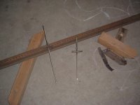
I don't know if I have a pic but 2x2 is way beyond whats needed for this job. We used a common old sign post as it had holes all along and dropped 3/8 all thread hangers similar to some of the pics, blocked it up with wood shims. Ours looked near identical to the one in the first pic. the hardest part was connection to an awkward engine. We looked at rigging a couple 2x4's like a window or door header where you allowed rods to come between would work, could screw gun pieces to it for support.
 
Last edited:

theoldwizard1

Well-known member
Joined
Feb 22, 2011
Messages
43,656
Location
SE MI
Keep in mind that structural members should be sized based on deflection rather than yield strength. Steel will deflect (bend in this case) significantly before it yields.

Isn't the old rule of thumb 2 or 3 times yield strength ?
 

May Pop

Well-known member
Joined
Aug 7, 2005
Messages
783
Location
Lake in the hills Il.
SBERRY
Thanks for adding a little common sense to this thread. 2x2x1/4 is plenty. This is not a structure but a temporary holder for the drivetrain. Yes a couple of supports to spread the load so it doesnt twist AND cause damage where its sitting. As for 2000LBS its the drivetrain 600 LBS max? Not the whole car.

Ron
 
To avoid these ads, REGISTER NOW!

zkling

Well-known member
Joined
Jan 23, 2007
Messages
16,939
Keep in mind that structural members should be sized based on deflection rather than yield strength. Steel will deflect (bend in this case) significantly before it yields.

Yes and no. Depending on the application, stress is primarily the determining factor. As I am sure you know, below yield; stress and deflection (strain) are linearly related by young's modulus. As one increases so does the other. Different applications requre different cases of study. In this case I don't see why a little deflection is going to hurt.

Two different examples. Take an airplane.

Deflection, inside the turbine you will be concerned about stress and deflection specifically when tight clearances are involved. The stress induced could cause a deflection that could eat up clearances between blades and seals.

Stress, if you watch certain aircraft in slow motion while leaving or touching the ground. A large deflection is usually present in the wings. In this case, deflection is not a huge concern. But stress is.

Isn't the old rule of thumb 2 or 3 times yield strength ?

Depending on the application. What you are talking about is safety factor. Some applications like elevators will go as high as 7x. Other things such as airplanes where minimal weight is important a safety factor may only be on the order of 1.2x. So the stresses and forces involved will need to be known very accurately.


Sberry is very correct. I would be much more concerned how you are going to rig this device up than the structural members that you use. Heck 2x4's would work if properly utilized.
 
Last edited:

sberry

Banned
Joined
Jun 18, 2005
Messages
35,747
Location
Brethren, Michigan
I used a common sign post. We got a couple of these so I sat down and did attachment brackets for a Freestar, it was a pain, no good way around it. Its not a center load but I used little plates about 3 inches for a flat washer to reduce point load that would occur from a nut, a couple big flat washers would have worked but had them and common blocks on out shelf. I remember I anchored something with a couple deck screws to keep it from sliding, the beam was the easy part.
 

Attachments

  • eng support.jpg
    eng support.jpg
    147.8 KB · Views: 148
  • block rack.jpg
    block rack.jpg
    143.5 KB · Views: 151

sberry

Banned
Joined
Jun 18, 2005
Messages
35,747
Location
Brethren, Michigan
I am not an engineer but grasp the concept of 1.5x or 5x and try to keep generalizations in mind, this is seat of the pants "looks good to me" engineering, with a "strong enough" saftey factor considering it isnt bouncing down a road in a service body.

If this was in a specialty shop where use may be hi then some design or purchace of a special tool may be practical but here its git er done. Sometimes it only takes a little to make it a lot, a 4x4 with hole bored thru it would be great. Bore a new hole for any different setups.
 

Albiemanmike

Well-known member
Joined
Jan 11, 2013
Messages
138
Location
CT.
I used a common sign post. We got a couple of these so I sat down and did attachment brackets for a Freestar, it was a pain, no good way around it. Its not a center load but I used little plates about 3 inches for a flat washer to reduce point load that would occur from a nut, a couple big flat washers would have worked but had them and common blocks on out shelf. I remember I anchored something with a couple deck screws to keep it from sliding, the beam was the easy part.

Now that there is some serious "git er' done" ingenuity right there. Bravo on that setup and I bet it didn't take long to come up with that arrangement.
 
OP
F

fordnut85

Well-known member
Joined
Sep 6, 2012
Messages
231
My theory is if you look at the first pic zkling posted, imagine that is a piece of square tubing but rather than the slot for the J hook I would have another piece of square tubing large enough to slide over the first tube with a piece if pipe welded to the side that the J bolt would go thru. That way the hook or hooks if I needed 2, could be positioned wherever needed. Yes I know this will pull on one side of the tube and will make it want to roll over however the supports on the side would prevent it from doing so. Another add on I have thought of would be another piece of square tube welded to the side of a piece of the larger tube to make a 3rd leg to the stand that could be positioned wherever needed for stability or for a longitudinal mounted engine (i.e. VW Passat). In my head it don't look nearly as redneck engineered as it sounds lol.

When I get a minute I will draw up what I'm thinking and post it.
 
OP
F

fordnut85

Well-known member
Joined
Sep 6, 2012
Messages
231
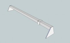
This is a rough sketch of what I got going on in my head.....well at least as far as the engine support goes lol.
engine support.jpg
 

koditten

Well-known member
Joined
Apr 10, 2008
Messages
5,528
Location
Midland, Michigan
1 1/2" tube will slide right into 2" tube. Would make it adjustable for different widths of fender aprons. As a person that uses these sizes of tube extensivly, I would have no problem using 1/8 wall.

Making it telescope inside of itself would make it take up less space when hanging on the wall.

Looks like a nice quick project. Let us see the final product.

KO
 

SiGmA_X

Well-known member
Joined
Aug 13, 2005
Messages
1,111
Location
Portland, OR
$50, harbor freight. Simple.

Or 2x2x3/16-1/4". You'll be plenty safe. Look at the OTC bar for ideas - its basically identical to your drawing...
 

racingtadpole

Well-known member
Joined
Dec 3, 2011
Messages
2,029
Location
The far side of crazy.. but sometimes Australia
1 1/2" tube will slide right into 2" tube. Would make it adjustable for different widths of fender aprons. As a person that uses these sizes of tube extensivly, I would have no problem using 1/8 wall.

Making it telescope inside of itself would make it take up less space when hanging on the wall.

Looks like a nice quick project. Let us see te final product.

KO

Use a length of 1.5 then make adjustable end plates and hook plates out of 2". Then everything is adjustable.
 
OP
F

fordnut85

Well-known member
Joined
Sep 6, 2012
Messages
231
Ok I really like that design. Might have to go back to the drawing board on this one. It would seem to me that if it was built out of 2 pieces of 1.5"x.75" rectangular tubing it would be stronger that the regular 2"x2" stuff since there is more surface area in the vertical plane. I like the idea of the lift point being in the center of the support beam.

I found this regarding the 4 leg engine support bar above. http://www.norcoind.com/norco/downloads/exploded/78099_Exploded.pdf
 

NUTTSGT

Super Moderator
Staff member
Joined
Sep 14, 2009
Messages
51,631
Location
Northern Central Ohio
I would think that a 2x2x1/4 wall would be plenty.

What size tube is the beam of your cherry picker ? It's only supported on one end and is hanging out how far ?
 

sberry

Banned
Joined
Jun 18, 2005
Messages
35,747
Location
Brethren, Michigan
I am not sure why the lift point in the center is preferable but,, this doesnt need to be as strong as it can be, only as strong as it needs to be.
 

koditten

Well-known member
Joined
Apr 10, 2008
Messages
5,528
Location
Midland, Michigan
I wondered about that as well. If I was building it, I would bore a series of holes on the top and bottom. You could move the hook point left of right to get a good weight distribution.

The strenght of the tube is in the horizontal surfaces. You could have holes driled every 4" and the strength would not be compromised.

KO
 
To avoid these ads, REGISTER NOW!
Top Bottom