To avoid these ads, REGISTER NOW!

Started building a 50´s style guitar amp

MBfreak

MEMBER EMERITUS
Joined
Dec 10, 2010
Messages
2,301
Location
Linkoping , Sweden
My son is into playing guitar, does it to relax from the pretty hard studies Five years of mostly math like integrating bessel functions or explaining the wonders of quantum computers. He certainly can do with some relaxation

He has a Marshal Valvestate and a couple of weeks ago he asked " How about building me a real valve amplifier. You have a degree in ancient electronics, bet you know about vacuum tubes!"

So I said , " Yes , sure, nice little project for a nerd "

Got hold of most parts, but still chase a 50s style 50 Watt output transformer for a AB1 2xKT66 style amp. This is probably the most defining component of a lead guitar amplifier from the 50`s. It has to sound just right!

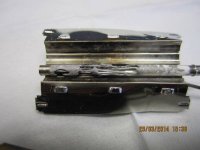
While doing breadboarding to try out some valve ideas I have also started on the chassis, which is an extruded aluminum profile. I attach some pics of the preliminary machining, more will follow when assembly starts.

Best regards
 

Attachments

  • mini-El Cheapo adaptor.jpg
    mini-El Cheapo adaptor.jpg
    57 KB · Views: 177
  • mini-Chassis milling.jpg
    mini-Chassis milling.jpg
    33.8 KB · Views: 180
To avoid these ads, REGISTER NOW!

theoldwizard1

Well-known member
Joined
Feb 22, 2011
Messages
43,225
Location
SE MI
Good luck !

Psst, "valves" are called "tubes" over here !

For you youngster, they look a little like incandescent light bulbs but act a little like FET transistors.
 

Tone-NY

Well-known member
Joined
Sep 24, 2012
Messages
143
Wow nothing like a hand built amp, you're a great Dad! Will be following this build. Thanks for sharing this.
 

Stuart in MN

Well-known member
Joined
Sep 8, 2005
Messages
23,141
Location
Minneapolis
When you get to building the cabinet, there are companies out there who sell vintage style cloth for the front of the speaker as well as vintage style leatherette for covering the case.
 

DekeT

Well-known member
Joined
Aug 12, 2011
Messages
2,234
Location
USA
Excellent project. Keep the pics and descriptions coming. Tubes is the way to go.
 

pacecar

Well-known member
Joined
May 2, 2012
Messages
236
Location
bryan, tx
I found this site pretty helpful when I was starting out

http://18watt.com

Lots of info on older amps

What circuits are you considering?

Old fender tweed, vox, marshal jtm?

Sent from my XT1058 using Tapatalk
 
Last edited:
OP
M

MBfreak

MEMBER EMERITUS
Joined
Dec 10, 2010
Messages
2,301
Location
Linkoping , Sweden
Hi to all.

The electrical design is interesting for any type of guitar amplifier. It is a lot more intricate than designing a good stereo amplifier where the aim is very low distortion and a flat frequency response from 10 to 25 kHz. Some tone controls and some attention how to drive the speakers.

But a guitar amplifier is part of the sound and special distortion and frequency response are integral parts. Musicians and designers have been collaborating on this for 50+ years. A bit hard to do that from scrtach, at least for me.

So , my design is from scratch, but I have studied and lifted freely from the old Marshall, Fender, Vox and a bunch of other designs.

If I could only find an original, undamaged output transformer from the 50´s, that would be ideal. But, no go. So I have settled for the Hammond top of the line unit, and hope for the best

Ola
 

exmaxima

Well-known member
Joined
Dec 10, 2009
Messages
89
While doing breadboarding to try out some valve ideas I have also started on the chassis, which is an extruded aluminum profile. I attach some pics of the preliminary machining, more will follow when assembly starts.

I've built a few amps for my son as well, and started a rather large project a few years ago that never materialized---I think I'm just getting to old for these things. In any case, though I put the chassis up for sale locally I thought you might like to see what I started:

http://chicago.craigslist.org/wcl/msg/4346919320.html
 
OP
M

MBfreak

MEMBER EMERITUS
Joined
Dec 10, 2010
Messages
2,301
Location
Linkoping , Sweden
Hi Pacecar,

thanks a lot for the mojo link. Interesting place. Wish I had known about them before.
I have bought Canadian made transformers from a reputable company some weeks ago. Will use these, for now.
However, in the true DIY spirit I have also bought lamination, a coil frame and copper wire, will do some calcs and then try making an output transformer myself. Easy for a mains frequency transformer, but will be interesting to see what frequency response I get on the output transformer.

Ola
 
To avoid these ads, REGISTER NOW!

exmaxima

Well-known member
Joined
Dec 10, 2009
Messages
89
However, in the true DIY spirit I have also bought lamination, a coil frame and copper wire, will do some calcs and then try making an output transformer myself. Easy for a mains frequency transformer, but will be interesting to see what frequency response I get on the output transformer.

Ola

In my experience, the key parameter for the OT is the inductance. For good speaker control (damping) at low frequencies you want as high of L as possible. You will be tweaking your overall response with the preamp section, but do not want the OT to fart out on the speaker.

If you look at some the best amplifiers (Dr Z, vintage Mesa, Sunn, etc), you will see that the OT is bigger than needed----that gives the extra inductance and cone control. The Hammond trannies would work well if you want a clean amp with punch. Same concept as the grossly expensive Mercury Magnetics "Fat Stack".
 

James_B

Well-known member
Joined
Jun 24, 2013
Messages
674
Location
Nova Scotia, Canada (started in Brisbane, Australi
I'm in for more. Valves were done and dusted by the time I got into the trade, although they hadn't long discovered electrons flowed backwards to what was first thought.
When I was doing my trade course, the external TAFE course covered just the semiconductor stuff and the new fangled digital circuits. On the other hand, the in-house training went back to vacuum tubes, relay circuits, and teleprinters, so we could work on the equipment that the organization was actually using.
 

volleyball

Well-known member
Joined
Aug 29, 2011
Messages
4,127
Location
NY, not NYC
I don't get the love of tube amps. I think people are just familiar with the distortion. Could be why reverb units came into popularity when amps went solid state.
And I grew up with tubes. I still have 2 caddies full of tubes and a briefcase size tester for when I worked on them so I know what they are.
When in electronics school, I had a room mate that built radios from parts.
In the US there are still lots of old tube amps to rebuild that doing one from scratch has to be a labor of love more than having one.
 
OP
M

MBfreak

MEMBER EMERITUS
Joined
Dec 10, 2010
Messages
2,301
Location
Linkoping , Sweden
For me, a guitar amplifier is MUCH more than getting a "stereo" type design right.
And why should I buy one when I can build one.
Semiconductors are great, but the tubes are an interesting technology.

And the few really skilled guitar players that I personally know, have an absolutely amazing ability to define what they want the sound to be.
They pick up nuances by ear that I find hard to even measure with top notch equipment. And they do it consistently and accurately.


That is why I am humble when it comes to guitar amps. To get the right sound is 10 % engineering and 90 % tweaking based on "non technical" but absolutely relevant comments from the player.

If you spend a couple of hours going thru the schematis of many units you will find a lot of similarity from 1950 to 1970, and the differences are miniscule.
But a skilled player hears them.

The guitar itself is much the same but the craftmanship to build a good one is totally beyond me.
But I have repaired a few, even rewound a Fender bridge pickup after very careful reverse engineering. The player was well satisfied.

And since they hear things I can not measure, if they say " tube amp" that is what is will be.

Best regards

Ola
 
Last edited:

racingtadpole

Well-known member
Joined
Dec 3, 2011
Messages
2,029
Location
The far side of crazy.. but sometimes Australia
In my experience, the key parameter for the OT is the inductance. For good speaker control (damping) at low frequencies you want as high of L as possible. You will be tweaking your overall response with the preamp section, but do not want the OT to fart out on the speaker.

If you look at some the best amplifiers (Dr Z, vintage Mesa, Sunn, etc), you will see that the OT is bigger than needed----that gives the extra inductance and cone control. The Hammond trannies would work well if you want a clean amp with punch. Same concept as the grossly expensive Mercury Magnetics "Fat Stack".


I initially read that and thought it sounded counter intuitive... then I did the maths... :lol: (theres a reason I specialise in RF not Audio :bounce:)
 
OP
M

MBfreak

MEMBER EMERITUS
Joined
Dec 10, 2010
Messages
2,301
Location
Linkoping , Sweden
WRT L ( inductance) in the OT, there is a lot more to it than getting a high inductance. The two primary winding halfs should be as close to each other thermally and in resistance so that the L/R from the two sides match over a wide temperature range.

And then there is the magnetic saturation which defines the sound at higher outputs and lower frequencies.
A ferromagnetic core is rather linear wrt I/U characteristics up to the part where the flux density reaches around 1,65 T, depending on the type or ferromagnetic core material that is used. The equation for this goes :
U*sqrt2= 2pi*f*T*A*n. For a given core area the maximum induced voltage at T 1,65T defines how useful/true the transformer will be for low frequencies, before saturation sets in. Losses in the core, winding capacitances sets the limit for high frequencies. The Hammond I bought tested our within +-2 dB at 15 Watts RMS output between 75 and 12 kHz, which is pretty good. ( I ran it backwards from a Marantz amplifier and with a pure resistive load on the "HT" side. How relevant this test is will be revealed once the soldering part of the job starts.

For now, it is all about converting a sturdy aluminum profile into a swiss cheese so that tubes, XFs, caps, potentiometers, jacks can be mounted. All screws will be threaded in the chassis, except for the two transformers. Then off to the powder coating the external surfaces black.

Hope to have the chassis back from painting next week, pics will then follow.

Hope to
 

1cargarage

Well-known member
Joined
Feb 16, 2014
Messages
409
Location
San Diego
This is a really interesting thread even though I am not fluent in electrical jargon. I will be taking my second physics course next semester (electricity and magnetism). Looking forward to it. I will be keeping up with this thread
 

exmaxima1

Well-known member
Joined
Jun 25, 2011
Messages
6,343
Location
Midwest
The Hammond I bought tested our within +-2 dB at 15 Watts RMS output between 75 and 12 kHz, which is pretty good.

Most guitar amps drive large cone type speakers w/o tweeters, so the high end is not really too much of an issue. I would be concerned that the low end is only 75 hz at 15 watts if you are using a KT66 P-P output section. Even if cathode-biased, that topology should do about 20-25 watts.

Are you sure the OT is big enough for this application?
 
OP
M

MBfreak

MEMBER EMERITUS
Joined
Dec 10, 2010
Messages
2,301
Location
Linkoping , Sweden
exmaxima.
Pse reread the post. I TESTED the Hammond and had only 15 W RMS power available. Hi Q Marantz stereo amplifier driven by a HP tone generator .I also tested it backwards, injecting on the spkr side and loaded on the HT side with resistors.
It was a trial test to get the feel for the OT.

It is good for 75 Watts with the PP KT66 operating at 460 V plate voltage, biased at I think it will be 37 mA at no signal.

Once I have the build completed a more realistic frequency response will be done at loads between 5 and 75 Watts.

As to the higher frequencies, I am forever baffled by the things a really good player can pick up by ear. Many of the nuances they consistently hear I can not measure with a pretty advanced B&K frequency response analyzer.

So the final tune of the amplifier will be don in cooperation with a guitar ace and by ear alone. I will do the electronic mods, he will say what is RIGHT.

Ola
 
OP
M

MBfreak

MEMBER EMERITUS
Joined
Dec 10, 2010
Messages
2,301
Location
Linkoping , Sweden
Hi.

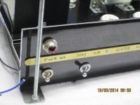
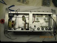
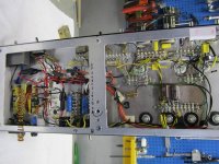
The mechanical part of the job is nearing completion and most parts are now installed. Wiring job is about to start, followed by testing and finally tweaking to get the sound that the player want to have . That will be the funniest part of the whole exercise.
Some pics :
 

Attachments

  • mini-Amp. Assy. front detail 1.jpg
    mini-Amp. Assy. front detail 1.jpg
    44.2 KB · Views: 61
  • mini-Amp. Assy.top view.jpg
    mini-Amp. Assy.top view.jpg
    46.9 KB · Views: 62
  • mini-Amp. Assy.2 fat KT66`s.jpg
    mini-Amp. Assy.2 fat KT66`s.jpg
    55.7 KB · Views: 60
  • mini-Amp. Assy.bottom view.jpg
    mini-Amp. Assy.bottom view.jpg
    60.4 KB · Views: 59
OP
M

MBfreak

MEMBER EMERITUS
Joined
Dec 10, 2010
Messages
2,301
Location
Linkoping , Sweden
50´s style guitar amp READY

Well , the electrical parts of the job is ready and all worked out well.
I have tested it on pure sine, puts out 50 W RMS from 45 Hz to 5600 Hz. Up to 14 kHz it drops off to 24 W RMS.
It is really silent , at no input and max volume the white noise is about -65 dB compared to 50 W RMS. It is white noise only, can not find even ONE significant frequency, and it all comes from the thermal noise in the first 12AU7.

Engraving of the brass 10x2 mm front and back and Marshall style knobs remains.

Now on to the woodworking to make a really solid and NICE cabinet, so it can be plonked down on top of a speaker cabinet with 4x12" Goldtops.

Real fun project.

One mishap, the rectifier tube melted at full power testing after 2 hours.
Replaced by silicon diodes, will find a better tube.

Ola
 

Attachments

  • mini-Amp ready rearview1.jpg
    mini-Amp ready rearview1.jpg
    45.2 KB · Views: 48
  • mini-Amp ready bottomview1.jpg
    mini-Amp ready bottomview1.jpg
    72.8 KB · Views: 58
  • mini-Amp ready topview1.jpg
    mini-Amp ready topview1.jpg
    51.6 KB · Views: 48
  • mini-Amp ready front 1.jpg
    mini-Amp ready front 1.jpg
    59.2 KB · Views: 50
  • mini-Dead  GUZ34 006.jpg
    mini-Dead GUZ34 006.jpg
    40.3 KB · Views: 42

59'trump

Well-known member
Joined
Apr 27, 2013
Messages
51
Re: 50´s style guitar amp READY

Absolutely exquisite work! I love hand wired amps and I hope the woodwork turns out well. Good luck and please post a demonstration video when it's complete!
 

Steinmetz

Well-known member
Joined
Oct 11, 2012
Messages
2,274
Location
Washington State
Hi to all.

The electrical design is interesting for any type of guitar amplifier. It is a lot more intricate than designing a good stereo amplifier where the aim is very low distortion and a flat frequency response from 10 to 25 kHz. Some tone controls and some attention how to drive the speakers.

But a guitar amplifier is part of the sound and special distortion and frequency response are integral parts. Musicians and designers have been collaborating on this for 50+ years. A bit hard to do that from scrtach, at least for me.

So , my design is from scratch, but I have studied and lifted freely from the old Marshall, Fender, Vox and a bunch of other designs.

If I could only find an original, undamaged output transformer from the 50´s, that would be ideal. But, no go. So I have settled for the Hammond top of the line unit, and hope for the best

Ola
Yes. The biggest problem is finding output transformers anymore. Unfortunately, most of them went to landfills some decades ago. Hammond's probably your best bet. Look at what Antique Electronic Supply in Tempe, AZ has to offer. I've bought lots of components for old tube gear from them.
 
OP
M

MBfreak

MEMBER EMERITUS
Joined
Dec 10, 2010
Messages
2,301
Location
Linkoping , Sweden
The guitar amp is nearing completion. I have ordered corner reinforcements for the cabinet which will arrive next week, and I am waiting for the front brass bezel to come bac from the engraving.
My son decided to name it White Noise, so that will go on the bezel between the Standby and Pres .

The tweaking is done to get the sound right when driving two 8 Ohm Marshall 12 " Goldtops. The clean channel was a little bit to subdued which we altered and the Pres ctrl ( negative feedback over the output and driver stages was a bit to high, so it was hard to get the right breakup at low Pres.
One objective was to get it humfree at all knob settings and that succeeded very well. The low level tubes have DC filament feed, parts are well separated and a lot of effort has been spent on starpoint earthing to avoid getting filter cap charging currents appear at the low level signal paths.
There is -72 dB white noise at full volume (ref the 42 W). RMS output is 42 Watts at 1 kHz sine, drops off to 39 W RMS at 45 Hz.

All in all, it worked out great.
Getting ready for a 4x12" speaker cabinet, Celestion or Marshall , or maybe a mix.

Best regards

Ola
 

Attachments

  • mini-Frontview 1.jpg
    mini-Frontview 1.jpg
    72.3 KB · Views: 40
  • mini-Rear view 1.jpg
    mini-Rear view 1.jpg
    64.6 KB · Views: 34
To avoid these ads, REGISTER NOW!
Top Bottom