To avoid these ads, REGISTER NOW!

Steel Square Tube Calc

ItsNemo

Well-known member
Joined
Mar 5, 2016
Messages
4,806
Location
Canada
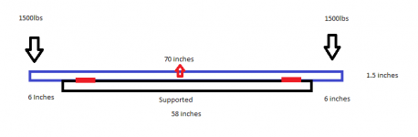
I have a mid-rise scissor lift that's not quite long enough to pick up the jack points on some vehicles. Want to build some simple extensions I can set on top so I can pick up longer vehicles at the pinch welds. Figure I need roughly 6 inches more at each end overhanging (load center point would technically be a couple inches off the end but figure 6 inches anyway for worst case), 58 inches is the current platform length, so 70 inches total length of the extensions. Need to safely carry around 1500lbs at each end (lift is rated for 6000 lbs total, would build one for each side so 1500 x 4 = 6000). Would like to use roughly 1.5 inch square tube tripled up (3 side by side welded together?). Can anyone do the math on it to figure out deflection and if I should use 0.100, 0.125, or 0.188 wall tube?

All the calcs I find online are always just center point load with ends supported.

High quality paint diagram attached.
 

Attachments

  • Steel Size.png
    Steel Size.png
    4.3 KB · Views: 107
To avoid these ads, REGISTER NOW!

astroracer

Well-known member
Joined
Jun 22, 2005
Messages
3,001
Location
Mid_Michigan
What is the current platform made from? Post a pic of it so we can see what you want to do.
What you are creating is a lever arm, so you need to look at those calculations to get an idea of what your loads will be at the supporting point.
If the current lift platform is sheet metal you should look into reinforcing the ends of the old platform to keep them from deforming.
Think about the weight too. 2 x 2 x 1/8 wall, at 6' long x 3 is about 40lbs.
Mark
 
OP
I

ItsNemo

Well-known member
Joined
Mar 5, 2016
Messages
4,806
Location
Canada
What is the current platform made from? Post a pic of it so we can see what you want to do.
What you are creating is a lever arm, so you need to look at those calculations to get an idea of what your loads will be at the supporting point.
If the current lift platform is sheet metal you should look into reinforcing the ends of the old platform to keep them from deforming.
Think about the weight too. 2 x 2 x 1/8 wall, at 6' long x 3 is about 40lbs.
Mark

It's a Bendpak MDS-6KF. I want to just set some heavy steel on top of it that's a bit longer to pick up the jack points on a new vehicle. It's only a few inches too short to get on their comfortably (I could force the issue but it would be partially on those yellow pieces).

This is with a vehicle that fits normally:

33430123_874643187773_9172134051971072000_o.jpg
 

ericlar80

Well-known member
Joined
Nov 14, 2014
Messages
362
Location
California
You should think about whether this loads the parts in your lift in a manner inconsistent with it's testing (it does). It may not be this added tube structure that fails...
 
OP
I

ItsNemo

Well-known member
Joined
Mar 5, 2016
Messages
4,806
Location
Canada
You should think about whether this loads the parts in your lift in a manner inconsistent with it's testing (it does). It may not be this added tube structure that fails...

It's no different than having pinch weld jack locations closer together. Or you could picture it the other way around, the tubes connected to the vehicle to narrow the footprint.

FYI, the vehicle isn't any longer overall or heavier than what I regularly put on the lift...it's just got a longer wheelbase and very specific jack locations as the pinch weld isn't exposed along the entire length of the vehicle (has side skirts).
 

ericlar80

Well-known member
Joined
Nov 14, 2014
Messages
362
Location
California
I'm not talking about the car's pinch welds, I'm talking about loading the lift itself differently than was intended. I'm guessing they didn't test it by point-loading the yellow piece at the very end of the platform. In fact, you will be creating a larger lever arm from where the connection point underneath the platform supports because you will be another 6 inches (or whatever) away from that point.

I think you are picturing the added bar as evenly distributing the load across the platform like a rocker panel would. But the bar is really going to bow up in the center slightly and put all the force at the ends of the platform and that what you need to be worried about here. The bar can definitely be made strong enough to support the car, but I'm not so sure the lift platform is up to task with how you've envisioned it. The bar needs to be very stiff.
 
OP
I

ItsNemo

Well-known member
Joined
Mar 5, 2016
Messages
4,806
Location
Canada
I'm not talking about the car's pinch welds, I'm talking about loading the lift itself differently than was intended. I'm guessing they didn't test it by point-loading the yellow piece at the very end of the platform. In fact, you will be creating a larger lever arm from where the connection point underneath the platform supports because you will be another 6 inches (or whatever) away from that point.

I think you are picturing the added bar as evenly distributing the load across the platform like a rocker panel would. But the bar is really going to bow up in the center slightly and put all the force at the ends of the platform and that what you need to be worried about here. The bar can definitely be made strong enough to support the car, but I'm not so sure the lift platform is up to task with how you've envisioned it. The bar needs to be very stiff.

Which is why I'm asking for deflection calcs to see how stiff it needs to be. The weight would never be on the yellow parts though, they taper slightly down from the blue main platform, so no contact there. I regularly load the lift with the contact blocks right at the edges of the blue which is within design spec for the lift.

I'm not asking it to do anything it wouldn't otherwise see in normal use. I can also easily put some thin rubber strips underneath (was planning on it actually to keep it from being metal on metal) to control precisely where the load is placed on the blue platforms.

To help visualize, see attached imagine the red blocks space the blue and black slightly and the red up arrow accounts for it bowing up in the middle but not contacting the main lift anywhere but the red blocks. This is absolutely no different than the load presented when a vehicle is directly on the lift with the rubber contact blocks on the pinch welds.
 

Attachments

  • Steel Size2.png
    Steel Size2.png
    5.4 KB · Views: 50

strutaeng

Well-known member
Joined
Dec 12, 2011
Messages
2,300
Location
Dallas, TX
Which is why I'm asking for deflection calcs to see how stiff it needs to be. The weight would never be on the yellow parts though, they taper slightly down from the blue main platform, so no contact there. I regularly load the lift with the contact blocks right at the edges of the blue which is within design spec for the lift.

I'm not asking it to do anything it wouldn't otherwise see in normal use. I can also easily put some thin rubber strips underneath (was planning on it actually to keep it from being metal on metal) to control precisely where the load is placed on the blue platforms.

To help visualize, see attached imagine the red blocks space the blue and black slightly and the red up arrow accounts for it bowing up in the middle but not contacting the main lift anywhere but the red blocks. This is absolutely no different than the load presented when a vehicle is directly on the lift with the rubber contact blocks on the pinch welds.

HSS 2x2x3/16 is working about 40% capacity and deflection is about 0.009" at the tips.
 
To avoid these ads, REGISTER NOW!
OP
I

ItsNemo

Well-known member
Joined
Mar 5, 2016
Messages
4,806
Location
Canada
You already have the 2x2 stock?

I would just go ahead and get some HSS4x2x3/16 if you are going to buy it...

No I don't have it yet, but my supplier doesn't have a lot of rectangular in stock usually and the doubled up tube should be slightly stronger (four vertical pieces rather than just two) even if it's a bit heavier.
 
OP
I

ItsNemo

Well-known member
Joined
Mar 5, 2016
Messages
4,806
Location
Canada
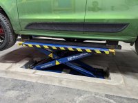
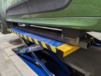
Here's the nearly end result...still need to clean them up and paint, but the structural stuff is done. There's pretty much zero deflection, I can't even slip a piece of paper underneath the tubes anywhere along the length of the blue lift platform. They're heavy (roughly 60-70lbs each) but I'm happy with how it's working out.
 

Attachments

  • PXL_20210309_225631137.jpg
    PXL_20210309_225631137.jpg
    150.9 KB · Views: 48
  • PXL_20210309_225644885.jpg
    PXL_20210309_225644885.jpg
    151.3 KB · Views: 47
To avoid these ads, REGISTER NOW!
Top Bottom