To avoid these ads, REGISTER NOW!

Storage height problem solved

Barry 2952

Active member
Joined
Sep 1, 2010
Messages
26
I've never been able to store the two Continentals with their tops up, and that's not very good for the tops, or the interiors.

StackedContinentals0002.jpg


It looks pretty cool driving by my house during the winter as the tail end of the Porsche is clearly visible in the front window.

StackedContinentals0001.jpg


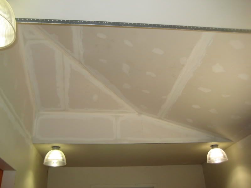
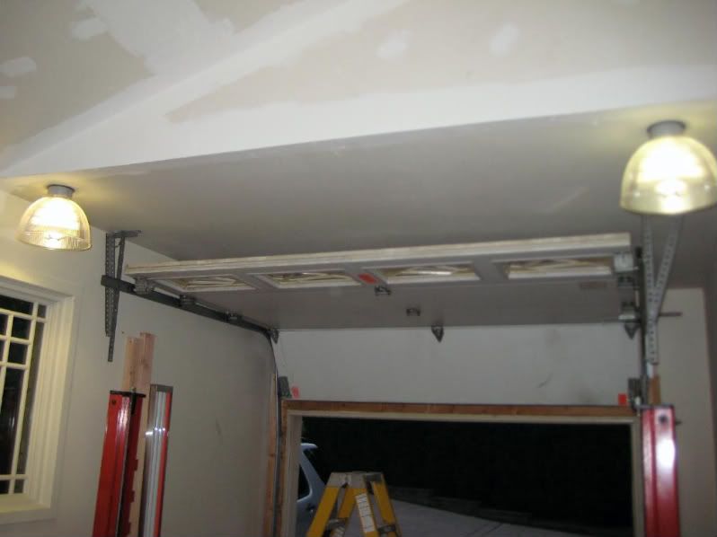
I only had 9'6" to work with. However, having built the house I realized that there was wasted space above.

IMG_1109.jpg


Doing a simple knuckle knock I was able to locate a 2x6 ceiling joist that ran the 10' width of the garage. I used a battery powered sawzall to cut the drywall in two spots about 8' apart. I used the edge of the joist as a guide for the blade. I barely penetrated the drywall as to not hit any of the wiring above.

Obviously, I had done too good a job of securing the drywall and I could only break it away in small pieces. Excessive amounts of adhesive will do that. I weigh about 280 and I could barely get the stuff to budge.

IMG_1111.jpg


I had forgotten that I had 6" of insulation blown in on top of the 6' of batt insulation. What a mess.

IMG_1112.jpg


IMG_1113.jpg


I was going to frame in a flat ceiling about a foot above the existing ceiling but I see no problem attaching the new drywall directly to the roof rafters over a 1" layer of insulation board. This will still allow proper air flow through my soffit vents and out the roof cap.

IMG_1114.jpg


IMG_1115.jpg
 
To avoid these ads, REGISTER NOW!
OP
B

Barry 2952

Active member
Joined
Sep 1, 2010
Messages
26
I needed to relocate some lights and the outlet for the garage door opener because I'm using a new type that turns the torsion bar rather than moving the door in a chain-driven manner. This will allow more space for a longer car stored on top.

yhst-16416632405890_2009_2468648-1.gif


I used the junction box for a new light location to extend the wiring for the new opened and used it to add two more 32-watt fluorescent lights.

IMG_1135.jpg


IMG_1136.jpg


Framed in the front slope.

IMG_1137.jpg
 
OP
B

Barry 2952

Active member
Joined
Sep 1, 2010
Messages
26
More info:

http://www.prodoorparts.com/products/167.cfm

Here's another problem. The car on top can't be very long because I loose 7 feet of the 23-foot deep garage to the garage door. Even more space with a traditional opener.

StackedContinentals0002.jpg


You can see the problem plainly here.

IMG_1158.jpg


I have more than 2 feet of wasted space above the garage door that could contain the back end of a car if the garage door hugged the ceiling.

IMG_1156.jpg


So, I had this brilliant idea that I could simply extend the vertical tracks and move the torsion spring assembly up by 16" along with the curved track. I would simply cut 16" off of the horizontal tracks and move the supports to the next closest ceiling joist. I figured the only thing I would need would be longer cables. I thought I came up with this brilliant idea all by myself, until I saw this. Someone beat me to it.

Topic1NotesImage22.jpg


I completed the framing and installed a vapor barrier. No need for insulation as it's an unheated space.

Ready for drywall.

IMG_1163.jpg
 
OP
B

Barry 2952

Active member
Joined
Sep 1, 2010
Messages
26
First two sheets of 5/8" drywall installed. Has the gravitational pull of the Earth changed in the last 14 years? Drywall sure seems to have gotten much heavier since I built this house. :(

Sure helps to be working off of an easily variable height platform. :D

IMG_1181.jpg
 
OP
B

Barry 2952

Active member
Joined
Sep 1, 2010
Messages
26
I've finished installing the drywall. My cuts weren't exactly perfect. Made too many assumptions. "Measure twice, cut once".

However, I did estimate the exact amount of drywall and overestimated by four 2 x 4s.

Mud is next.

IMG_1184.jpg


IMG_1183.jpg
 
OP
B

Barry 2952

Active member
Joined
Sep 1, 2010
Messages
26
First coat of drywall mud. Almost done.

IMG_1185.jpg


Door track modification:

Step one is taking the tension off of the torsion springs. This isn't rocket science, but it's very dangerous.

The spring holder hs a hub with two 3/8" suare head bolts to tighten the hub to the torsions shaft and it had 4 1/2" diameter sockets spaced 90° apart. The object is to add enough spring torsion to pull the cables up on their winding drum. Too little tension and the door will be heavy. Too much tension and the door won't stay closed.

The white stripes you see are winding stripes. Each one denotes one full revolution of the spring. It was painted on the spring as a straight line at the factory.

Seven stripes is typical for a heavy insulated door. Eight to ten is about max.

IMG_1187.jpg


IMG_1188.jpg


This is a normal track arrangement. The top hinge is further from the door, forcing it closed as the door lowers. I needed to keep this feature.

IMG_1189.jpg


By taking the tensions off of the spring I was able to remove the cable that pull up the bottom of the garage door on both sides. The torsion spring rotates the drum reeling or unreeling cable. It is designed to give the door very little weight in either direction.

IMG_1190.jpg


There will no longer be a need for this type of connections as the new opener simply turns the torsion bar.

IMG_1191.jpg


This bracket will be split in two with the upper half 16" above the original location.

IMG_1192.jpg


Secured the door so that it didn't fall in on me.

IMG_1195.jpg


Removed the horizontal tracks and determined that the angle iron support needed to be moved 3 1/2" away from the track curve. High school algebra rules!

IMG_1196.jpg


I needed the bottom part of this bracket to stay where it was.

IMG_1197.jpg


I cut the flange off with the abrasive blade in my power miter box.

IMG_1200.jpg


Installed the upper part of the bracket 16" above the lower half.

IMG_1201.jpg


Secured the rails and checked to see that they were the same length.

IMG_1203.jpg


Cut 17" off of the end of the horizontal rail to be used as filler between horizontal and vertical track

IMG_1204.jpg


New wood supports ready to receive rails.

IMG_1205.jpg


Installed torsion springs and horizontal rails.

IMG_1206.jpg


Trimmed the 17" pieces of rail with an 8° parallel angle on each end and filled the distance between the rails while maintaining the exact original position of the upper roller.

IMG_1208.jpg


IMG_1210.jpg


Had to put an additional 1/2 turn on the torsion springs over the original tension but it glides much easier now. Putting the last two 1/4 turns were tough. That's probably all the original installer could muster.

IMG_1211.jpg


IMG_1223.jpg


Tomorrow I'll install the side-car opener.
 
OP
B

Barry 2952

Active member
Joined
Sep 1, 2010
Messages
26
Here's the completed installation of the door opener. It's pretty slick.

IMG_1232.jpg


The box on top has two hubs to turn the torsion shaft so it can be mounted right-hand or left-hand.

The box contains the electronics and the 24-volt DC drive motor.

IMG_1226.jpg


Below the box is a tension sensor that reacts to a fluctuation in lift cable tension and shuts the system down if a cable breaks or the door gets jammed.

IMG_1225.jpg


Below that is a dead bolt that closes, blocking the roller from moving up after the door goes down. This car be released from inside the garage in a power failure or in manual mode.

IMG_1228.jpg


The manufacturer recommends mounting the blockage sensors 6" off the floor to detect small pets or children. I had to install mine 16" off the ground because the structure blocked putting them any lower. Since I have a tall dog and children aren't allowed in the house, I'll think I'll be OK.

IMG_1230.jpg


The last item to be installed is a remote light fixture that uses an RF signal to turn on an off, controlled by the master unit and the door control switch.

IMG_1231.jpg
 

ishiboo

Well-known member
Joined
Oct 27, 2010
Messages
9,481
Location
Oshkosh, WI
I was going to frame in a flat ceiling about a foot above the existing ceiling but I see no problem attaching the new drywall directly to the roof rafters over a 1" layer of insulation board. This will still allow proper air flow through my soffit vents and out the roof cap.

Those are not floor joists, they are roof joists - their job is not to support weight, but to act in tension to prevent the roof from splaying out with weight on it.

Weight on that area of the roof now pushes the walls "apart" from each other. You may not notice any issues, but thats why the joists are there. It is definitely now a weakened roof.

I would at the very least make sure the roof members are connected via hurricane clips/straps to the top plate. Given the width of this area I don't think you'll have an issue unless you have it inspected :)

Are you located in an area that gets snow?
 
OP
B

Barry 2952

Active member
Joined
Sep 1, 2010
Messages
26
You didn't know that the header above the windows is a triple 1 3/4" lam beam bolted together with 3/8" carriage bolts holding it together. :beer:
 
To avoid these ads, REGISTER NOW!

ishiboo

Well-known member
Joined
Oct 27, 2010
Messages
9,481
Location
Oshkosh, WI
You didn't know that the header above the windows is a triple 1 3/4" lam beam bolted together with 3/8" carriage bolts holding it together. :beer:

The header is irrelevant, it's not the force of gravity down - its the force pushing the walls outwards. Your top plates and bottom plate are stronger than the LVL in that direction :) I'm sure things will be fine, but those joists were there for a reason other than just hanging the ceiling :)
 
OP
B

Barry 2952

Active member
Joined
Sep 1, 2010
Messages
26
I beg to differ. The lateral strength of the triple lam beams bolted together offsets any outward force.
 

brwbier

Well-known member
Joined
Aug 14, 2009
Messages
61
Location
Sheboygan, WI
I would like to thank you for doing all the work of figuring this out. I want to raise my doors also and this is exactly what I needed.
Thanks again, I owe you a beer.
Brwbier
 

csp

Well-known member
Joined
Mar 23, 2010
Messages
5,719
Location
Franktown, CO
Every window/door opening has a header above it. They have nothing to do with lateral forces exerted by the weight of the roof or snow that might be on it.
 

larry4406

Well-known member
Joined
Jan 27, 2006
Messages
19,089
Location
Northern Virginia
I think that ishiboo is trying to say that the ceiling joists also probably acted as collar ties in the framed roof system and they are now gone which may contribute to the roof "squating" down over time in turn pushing the side walls out. For example, take the letter "A" and push downward on the top (pushing = weight of the roof, snow, etc). The horizontal line (collar tie) resists spreading of the rafters. Now remove the collar tie and repeat - depending on loads, the legs spread and pushes the walls apart.

I saw the Wayne Dalton I-drive picture and thought you were making a horrible mistake and then saw the Liftmaster. I had a I -drive and it was a POS and replaced it with the Liftmaster.

I would have kept insulation.
 

green.bubbly

Well-known member
Joined
Dec 14, 2008
Messages
2,156
Location
Lafayette, LA
Great write up. I always admire people that can actually stop and take pictures during a project. I always want to but it never happens.

Nice job and I bet your lift made a great scaffold.
 

sneezer41

Well-known member
Joined
Oct 8, 2007
Messages
407
Location
People's Republic of Mass
I had the same initial thought, but I think he has thought it out well. Study the structure, and I think it does not have a problem, given that it is very narrow, he has essentially made a crude truss on one side, and yes that glulam is going to help, since the wall needs to bend to let the roof drop, and now it cannot bend.
 

scott37300

Well-known member
Joined
May 5, 2010
Messages
3,450
Location
Wisconsin
Does this beam run corner to corner without any breaks?

I have seen a two car garage that only had a couple joists(ties) and the walls were bowed out about 6 inches on each side, including the front which had a big header for the garage door opening. The homeowner used some cable to make some ties to stop the walls from falling down and roof caving in. Not a pretty site!
 
OP
B

Barry 2952

Active member
Joined
Sep 1, 2010
Messages
26
Not a problem. Did the job 3 years ago, had plenty of snow and there's no movement. The opening in the ceiling is under 8 feet.
 
To avoid these ads, REGISTER NOW!
Top Bottom