cdestuck
Well-known member
I have a wiring problem and I need some help on. Behind my garage I build a covered area 40 foot long for some storage. In this area I put for jelly jar light fixtures for lighting.
The power first goes to the four fixtures and just passed the last picture I have my wall switch. Wiring is 14 gauge and I have 100 W bulbs in the fixtures.
I wired each fixture just as this picture shows. But when I connected power and turned on the single pole switch at the far end of the four lights I only get a very dim light from each of the four bulbs. I have a good line feeding this circuit but still bulbs are very dim. (Regular bulbs, not cfl or led).
Could it be that you just can't wire 4 fixtures and then to switch at far end? I did notice that if I take one bulb out of fixture that the other 3 bulbs go out which I understand as it's opening the circuit. Any ideas guys??
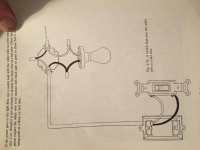
Attached pic is just how I wired each fixture.
The power first goes to the four fixtures and just passed the last picture I have my wall switch. Wiring is 14 gauge and I have 100 W bulbs in the fixtures.
I wired each fixture just as this picture shows. But when I connected power and turned on the single pole switch at the far end of the four lights I only get a very dim light from each of the four bulbs. I have a good line feeding this circuit but still bulbs are very dim. (Regular bulbs, not cfl or led).
Could it be that you just can't wire 4 fixtures and then to switch at far end? I did notice that if I take one bulb out of fixture that the other 3 bulbs go out which I understand as it's opening the circuit. Any ideas guys??
Attached pic is just how I wired each fixture.