To avoid these ads, REGISTER NOW!

Suitable replacement motor?

TheEquineFencer

Well-known member
Joined
Jan 15, 2009
Messages
9,278
Location
Farmville, NC 27828
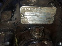
I built a "cutter" I use behind a tractor for trimming the ditch banks around the farm. It's built with what I had laying around and is powered by 3500/4000 watt Champion generator. The motor is an old reversible GE motor with a drum switch. It's a 5KC63AB776 1/2 HP 1725 "K" locked KVA per HP rating.

Now, here's my "problem"...the generator I know is just barely big enough to start it, it runs it fine, if I "bog" the disc blades in the dirt by accident, it lugs the generator down and it's hard for it to pick the motor speed back up to speed because the generator Hz drops so low. If I switch the load (motor) off then back on it picks it up fine. My guess is the Hz drops so low it goes back into start internally and doesn't have the Hz to pick the load back up.

Is there another motor that will be better suited with a lower inrush/start circuit than the motor I have? The reversing ability of the motor is nice, but not a must. I'm looking a cheap way to get it to work better without having to buy a bigger generator.

Who sells one or what can I look for to salvage one from? The one I have has a fixed 4 bolt base and a 3/4 shaft.
 

Attachments

  • data tag on old half hp motor.jpg
    data tag on old half hp motor.jpg
    110.7 KB · Views: 75
To avoid these ads, REGISTER NOW!

Bretny

Well-known member
Joined
Jul 31, 2017
Messages
3,918
Location
Dutchess county NY
Pto would be best but mabe dosnt have one.

What about a lawn mower engine? There prety cheap used and going to be way more efficient.
 
OP
T

TheEquineFencer

Well-known member
Joined
Jan 15, 2009
Messages
9,278
Location
Farmville, NC 27828
OK guys, let's stick to the subject of the electric motor please.

Reason being, it's not built anything like a conventional PTO driven ditch bank cutter. Second, this can be installed on the back on a very small compact tractor...a regular one would turn a small tractor over. It's designed to cut grass like when you weed eat.

A used ditch bank cutter that is worn out around here starts around $1500.00 USD. All I have in this is some time and the steel tubing for the frame...about $300.00 USD and it works for the most part, at least well enough I've cut the ditches on the 20 acres we live on. Everything I built it with is salvage materials, belts, pulleys, spindles, actuators ect.

Now, back to the question I asked, what would be a suitable replacement motor that might be as or more efficient?
 

Bert_

Well-known member
Joined
Dec 24, 2016
Messages
9,780
Location
NW Iowa
Since you don't like the pto idea how about a hydraulic motor? Or the above mentioned gas engine. An electric motor driven by a generator is always going to be a less than ideal setup.

Is your motor a capacitor start motor? They have less inrush and better torque than the cheaper split phase type
 
Last edited:
OP
T

TheEquineFencer

Well-known member
Joined
Jan 15, 2009
Messages
9,278
Location
Farmville, NC 27828
Since you don't like the pto idea how about a hydraulic motor? Or the above mentioned gas engine. An electric motor driven by a generator is always going to be a less than ideal setup.

Is your motor a capacitor start motor? They have less inrush and better torque than the cheaper split phase type

PTO/Hydraulic is off the table, I'm totally rebuilding everything with money hungry parts.

The gas engine idea would work, but it'd be a PITA to have to fab all the pivot points for bearing and pulley. The engine would have to sit where the generator sits to stay flat. The deck rotates from straight out to the side up or down 90*, a gas engine would not last long running on it's side.

As to the question of the motor, the picture of the data tag is posted. It's actually quite a special motor compared to most from what I've been reading up on it. Yes it has a capacitor.

I'm not a guru on motors, that's why I posted this. I'm hoping someone that really knows electric motors chimes in and lends some insight. Maybe add more capacitance? But I'm thinking with the motor bogging the generator down, it would not help as it would not be charged enough to help out. I don't know, "that's above my pay grade" as RJ would say....
 
Last edited:
OP
T

TheEquineFencer

Well-known member
Joined
Jan 15, 2009
Messages
9,278
Location
Farmville, NC 27828
Engaging Speed 1800 RPM is what comes in the clutches I just looked up. I'm trying to find a contact number for the OEM to see if there's lower RPM springs available...it's a 1725 RPM motor....
 

MoonRise

Well-known member
Joined
Nov 5, 2010
Messages
4,031
Location
NJ
TANSTAAFL.

Meaning, you bog down the existing 1/2 hp electric motor and the gen set doesn't have enough oomph to get the motor back up to speed.

No matter what you do with your existing setup, you will still have a 1/2 hp electric motor running off of the same gen set.

If you are bogging the electric motor, then you either need to have more power available from the motor (replace the electric motor with a higher hp one, but that means that your gen set can't drive the motor) or you put in some sort of slip clutch (make it so that the drive belt can slip maybe?) between the electric motor and the cutter head.

But talking about efficiency as you mentioned it, you are taking gasoline and turning it into rotary motion in the generator, then turning that rotary motor into electricity in the gen set, then turning that electricity back into rotary motion in the electric motor and then running that rotary motion through some sort of belt-pulley-whatever arrangement.

Unless you can really scrounge something up on the cheap, about the least expensive way I can think of to get mechanical power to your cutter head would be the $99 (on sale about every month or so :D ) HF 6.5 hp gas engine. Rig up your scrounged belts and spindles and pulleys off of that down to your cutter head. Maybe scrounge a CV joint from something in the junkyard to give you the ability to run rotary motion through some adjustable and variable angles from the gas engine down to the cutter head.
Replacing your AC electric motor with something more efficient and more powerful is almost certainly going to cost more than that $100 HF gas engine.

Maybe some sort of flywheel device on the cutterhead or off of the electric motor shaft to enable the electric motor to not bog down so much?

How about this AC electric motor from Surplus Center? 1 hp, draws 10 amps at 115 V AC, TEFC and ball bearings? You'd have to adjust your drive pulley though, as this motor has a 7/8" dia shaft. Same rpm as your existing motor though, 1730 rpm. Only $150, plus shipping.

https://www.surpluscenter.com/Elect...5-208-230-Volt-AC-Farm-Duty-Motor-10-2912.axd
 
OP
T

TheEquineFencer

Well-known member
Joined
Jan 15, 2009
Messages
9,278
Location
Farmville, NC 27828
TANSTAAFL.

Meaning, you bog down the existing 1/2 hp electric motor and the gen set doesn't have enough oomph to get the motor back up to speed.

No matter what you do with your existing setup, you will still have a 1/2 hp electric motor running off of the same gen set.

If you are bogging the electric motor, then you either need to have more power available from the motor (replace the electric motor with a higher hp one, but that means that your gen set can't drive the motor) or you put in some sort of slip clutch (make it so that the drive belt can slip maybe?) between the electric motor and the cutter head.

But talking about efficiency as you mentioned it, you are taking gasoline and turning it into rotary motion in the generator, then turning that rotary motor into electricity in the gen set, then turning that electricity back into rotary motion in the electric motor and then running that rotary motion through some sort of belt-pulley-whatever arrangement.

Unless you can really scrounge something up on the cheap, about the least expensive way I can think of to get mechanical power to your cutter head would be the $99 (on sale about every month or so :D ) HF 6.5 hp gas engine. Rig up your scrounged belts and spindles and pulleys off of that down to your cutter head. Maybe scrounge a CV joint from something in the junkyard to give you the ability to run rotary motion through some adjustable and variable angles from the gas engine down to the cutter head.

Replacing your AC electric motor with something more efficient and more powerful is almost certainly going to cost more than that $100 HF gas engine.

Maybe some sort of flywheel device on the cutterhead or off of the electric motor shaft to enable the electric motor to not bog down so much?

How about this AC electric motor from Surplus Center? 1 hp, draws 10 amps at 115 V AC, TEFC and ball bearings? You'd have to adjust your drive pulley though, as this motor has a 7/8" dia shaft. Same rpm as your existing motor though, 1730 rpm. Only $150, plus shipping.

https://www.surpluscenter.com/Elect...5-208-230-Volt-AC-Farm-Duty-Motor-10-2912.axd

Most of what you say/suggest is accurate. Once again, I'm not rebuilding the entire cutter.

Is there an electric motor that will not be as hard to bring back up to RPM as what I have? One with less inrush and a better start circuit? The motor I am presently using is probably 50+ years old. I'm sure the technology has improved...
 

MoonRise

Well-known member
Joined
Nov 5, 2010
Messages
4,031
Location
NJ
The motor I listed only draws 10 amps at full load at 115 V.

Your 3000 watt gen set should be able to run that.

But as I mentioned, there is no free lunch.

Bog the electric motor and then the gen set has to bring it back up to speed.

A flywheel might help lessen the cutter head and electric motor from bogging as easily.

But not much will help if you bury the cutter head in the ditch bank. :lol:

A slip clutch (or slipping belt drive pulley) somewhere in the drive system might help keep from bogging the electric motor if you jam up the cutter head.
 
OP
T

TheEquineFencer

Well-known member
Joined
Jan 15, 2009
Messages
9,278
Location
Farmville, NC 27828
The motor I listed only draws 10 amps at full load at 115 V.

Your 3000 watt gen set should be able to run that.

But as I mentioned, there is no free lunch.

Bog the electric motor and then the gen set has to bring it back up to speed.

A flywheel might help lessen the cutter head and electric motor from bogging as easily.

But not much will help if you bury the cutter head in the ditch bank. :lol:

A slip clutch (or slipping belt drive pulley) somewhere in the drive system might help keep from bogging the electric motor if you jam up the cutter head.

The inrush at starting is also what I have stay under also, some motors it seams has upwards of 350% inrush at start up.

I guess I'll have to do like I do a lot of other things, do a lot of reading and learning...mainly about motors to see what has the least inrush at start up and starting under load...

Permanent Split Capacitor motor, Capacitor Start Induction motor, or a Split Phase motor seem to the choices...Are you familiar with those three types?
 

matt_i

Well-known member
Joined
Mar 14, 2008
Messages
10,753
Location
SE Michigan
To get more torque you need more poles in the motor.

I probably have a few facts wrong, but as I recall

2 pole is 3450, 4 pole is 1725/1750, There's like a 1200-ish rpm motor (think 6 pole) and a 900-ish rpm motor ( think 8 pole).

The poles add more iron and more copper and get expensive and HEAVY. They are not common. But it would give you more torque.

Were it me, I'd wire a drum switch between the gen and the motor. If it bogs, disconnect it, allow gen to regain speed, and then reconnect it, electrically speaking.

If that doesn work then I'd focus on PTO power. More reliable and so much more of it.
 
Last edited:
OP
T

TheEquineFencer

Well-known member
Joined
Jan 15, 2009
Messages
9,278
Location
Farmville, NC 27828
To get more torque you need more poles in the motor.

I probably have a few facts wrong, but as I recall

2 pole is 3450, 4 pole is 1725/1750, There's like a 1200-ish rpm motor (think 6 pole) and a 900-ish rpm motor ( think 9 pole).

The poles add more iron and more copper and get expensive and HEAVY. They are not common. But it would give you more torque.

Were it me, I'd wire a drum switch between the gen and the motor. If it bogs, disconnect it, allow gen to regain speed, and then reconnect it, electrically speaking.

If that doesn work then I'd focus on PTO power. More reliable and so much more of it.

Forget PTO Power. It'd turn a small tractor over, is cost prohibitive and once again, I'm not rebuilding the entire mower.

I do have a drum switch as you suggested and I do what you suggested. I'd like to not have to be switching it. I need a motor that will come back up to speed when the "load" is removed.

Interesting comments about the different poles in a motor...I didn't know that...
 
To avoid these ads, REGISTER NOW!

TractorJeff

Well-known member
Joined
Dec 8, 2013
Messages
3,309
Location
Elkhorn, WI
I'm surprised that your gen won't recover that motor unless it is the flywheel effect that is killing you?
I would sooner assume you need at least one horsepower to do the cutting?
 

American Locomotive

Well-known member
Joined
Jan 8, 2017
Messages
11,016
Location
Rhode Island
Either something is wrong with your generator, or something is wrong with your motor. It's just a boring old capacitor start 1/2 hp motor. Your 3500 watt generator should have no problem starting a motor twice or three times that size. My 3500 watt generator starts my 240v submersible well pump just fine.

But really, you should just rework the thing to use a gas motor. Get something like a Honda GX35, and hook it up with appropriate chain/sprocket reduction to get the proper speed. The GX35 is a mini 4-stroke that can operate in any position, and puts out up to 1.3 HP.
 
Last edited:

walta

Well-known member
Joined
Jan 13, 2017
Messages
2,313
Location
Dutzow Missouri
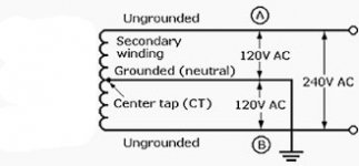
If you generator is able to produce 240 volts and you are feeding the motor 120 volts ½ of the generators potential is being wasted. If you rewire the system to run on 1/2 HP 240 Volts motor, the motor will still produce the same ½ horse power but it should start better and may not bog down as much.

If you stay 120 V and changed from an induction motor to a universal motor you would get more torque and faster recovery at the expense of shorter motor life. A universal motor will have brushes. Look for an old electric chain saw or circular saw.

Walta
 

bjcouche

Well-known member
Joined
Sep 11, 2010
Messages
509
Location
Ohio
OK, let me add my $0.02 as to what I think is going on and some potential suggestions. You know that with the generator running at 3600rpm (60Hz) it is able to easily start the motor. When you start the motor it draws 300% or so rated current until it get's up to near full speed. When you start the motor it likely takes less than a second to get up to full speed.
When you bog the mower down, you are doing so for a few seconds, and during that time the motor slows enough to engage the start winding thus drawing 300% ish current. 300% of 7A at 120V is about 2520W. Now I know 2520W is less than the generator rating of 3000W, but you are placing that electrical load on 1/2 of the generator's windings. It's also possible that the stall / breakdown current of the motor is more than 300%. The rule of thumb for 3 phase motors is 6X-10X rated current. Single phase motors have lower breakdown currents.
Now when your electric motor is drawing 300% current, you aren't getting 300% torque, less than 150% more likely.
Back to the generator, once the gas engine starts slowing down, it's torque capability and thus horsepower drops like a rock. Newer fixed jet carb engines with overhead valves have extremely peaky torque curves. Once you add torque to it's maximum value and the speed starts to slow, it will imediatly stall as the slower it runs, the less torque it can produce, the more it slows, etc. etc. until rpm=0.
A larger generator could help your situation, as also changing the motor to 240V. But what might be better options is to look at a speed clutch on the electric motor, or using a universal motor has me intrigued. A circular saw motor might not be such a good idea as they are designed for intermittent duty with time to cool down between cuts... But they do make universal motors for corded push lawnmowers.... A universal motor draws more current as you slow it down, but it also produces more torque... Depending on what is causing your motor to bog down though, a universal motor might be problematic too, as if you slow it down too much by contacting an immovable object (the earth) it will draw as much or more current as the induction motor, and you're back to the same problem...
Brian
 

TractorJeff

Well-known member
Joined
Dec 8, 2013
Messages
3,309
Location
Elkhorn, WI
Quote: "Back to the generator, once the gas engine starts slowing down, it's torque capability and thus horsepower drops like a rock. Newer fixed jet carb engines with overhead valves have extremely peaky torque curves. Once you add torque to it's maximum value and the speed starts to slow, it will immediately stall as the slower it runs, the less torque it can produce, the more it slows, etc. etc. until rpm=0."

Brian,
Good Info!
Never really thought about it from the Engine performance side!
Thanks!
Jeff
 
OP
T

TheEquineFencer

Well-known member
Joined
Jan 15, 2009
Messages
9,278
Location
Farmville, NC 27828
The last three post are pretty much are on track. I think a universal motor might work better...switching to 250V might help also....But not an option, it's 120V only....

I have a 29.2A@ 120V and it rated at 14.6A@240V, take into consideration the starting inrush.

IMO Amps are amps and wattage is wattage at 120V or 240V it's the same energy expended. The only advantage I see might be less Voltage drop for the wire size....

OK, what motor would you go to? Again, forget rebuilding the entire cutter, that as I've said numerous times before is OFF THE TABLE.
 

walta

Well-known member
Joined
Jan 13, 2017
Messages
2,313
Location
Dutzow Missouri
The way your generator works you 14.5 amp of 125 to one outlet and another 14.5 amps to the second 120 outlet. So yes the label says 29 amps at 120V but your biggest single 120V load is 14.5

Walt
 

Attachments

  • 1.jpg
    1.jpg
    10.1 KB · Views: 7
OP
T

TheEquineFencer

Well-known member
Joined
Jan 15, 2009
Messages
9,278
Location
Farmville, NC 27828
The way your generator works you 14.5 amp of 125 to one outlet and another 14.5 amps to the second 120 outlet. So yes the label says 29 amps at 120V but your biggest single 120V load is 14.5

Walt

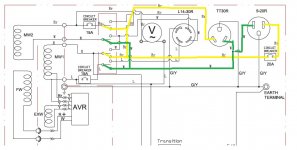
I'm glad you posted...I went back and looked at the wiring diagram for this generator. https://y79961nbs4u2hvbnwronx9zx-wp...-content/uploads/2017/08/46598-om-english.pdf

I've been running it with it switched to 120V only, not 120/240 and I've been running it on the 20A outlet. This oulet is only using one set of windings. If you look at the diagram, S21 page, it looks like if I install a plug onto my cord and plug into the 30A outlet I'd be using both 120V windings with it switched to 120V. It looks like with it on 120V only it parallels the 120V windings. Look at the diagram and see what you think?

I'll try to get to Lowes and get another 30A plug and try it that way the next time I cut with it.
 

Fasthotrod

Well-known member
Joined
Dec 14, 2015
Messages
218
Location
Oklahoma
I'm glad you posted...I went back and looked at the wiring diagram for this generator. https://y79961nbs4u2hvbnwronx9zx-wp...-content/uploads/2017/08/46598-om-english.pdf

I've been running it with it switched to 120V only, not 120/240 and I've been running it on the 20A outlet. This oulet is only using one set of windings. If you look at the diagram, S21 page, it looks like if I install a plug onto my cord and plug into the 30A outlet I'd be using both 120V windings with it switched to 120V. It looks like with it on 120V only it parallels the 120V windings. Look at the diagram and see what you think?

I'll try to get to Lowes and get another 30A plug and try it that way the next time I cut with it.

Not exactly... if you look at the diagram closely, you will see that the wiring is tied together after the voltage selection switch. When you select 120 VAC on the switch, the generator windings are placed in parallel and in-phase. I took the liberty of drawing on the schematic and removing the wiring that was not enabled when selected to 120 VAC below.

61C99--dJ8u0yuQsHEGsk4DlWdqdoQqXCCKyA7T0QFJ_EC0omqKMtq_-SP-H3mIBcMWNYYxQbENpbJeaR5_I7u8lwjnglVUoLsNlZVhCCvk2haXJLUeQlvnNFileoeWPBZQhJW-e4pDmY3rrFlWBkFHvVspMzkKQ-mvGix21FByQMchppbzjDmOqzPZ0XMOWFUCfqLaZgEvTzHCn6sAa5cxb9GSSa_0mYmHwU1Rn--1RaZQiQvKzBvebefURvHJcjC2ZgX3PoCTZACnm4LNQiSdkLTMmi56kc7AtEo584UEUZEEYwH2SeB93BpOyv5Y1wJq95pkyLGvmLBEtO56PfqGJHNotE_IBZFAWaCkXHMNY2rUIbRB10p49fvO7DuL8rnqKqLM_mEMwwPinayzpN10FMus0EqlYHxEUwisngz5bDsfQ4cbMxMnJc-TVvw1Vtkq8mYxaaz1lYRSwNdlvn4MhMQ1l1FE1dAlA4FjZtLhWRrN42vsGojA3W_z-7fFYS3sxoM63xJpCubttPOuBrCMZH8cvp73KLS8mZRQBRb4y54aiCDul5mvsJln6Y0XpWYRhYJtfQ5NLWqDxgB3I3-zCMXG6WNp_XC9Pn0Tt=w1151-h748-no


The individual windings are protected by 15A breakers before the switch. Once the connections pass through the switch, the brown wire (Br) and red wire (R) are tied together. The white wire (W) and blue wire (L) are tied together. This places both windings in parallel for a total available output of 30A, which feeds the 30A outlet. The 20A outlet is tied to the same point, but is provided additional circuit protection by the 20A breaker at the outlet due to it's current/ampere rating.

So if you are not tripping the 15A breakers or the 20A breaker, then odds are using the 30A outlet will not help you because you aren't really gaining anything.

Mark
 

Fasthotrod

Well-known member
Joined
Dec 14, 2015
Messages
218
Location
Oklahoma
The way your generator works you 14.5 amp of 125 to one outlet and another 14.5 amps to the second 120 outlet. So yes the label says 29 amps at 120V but your biggest single 120V load is 14.5

Walt

On some units, that is correct... but his has a selector switch that allows the alternator to switch the wiring for the individual windings. (Restrapping made easy.) In the 120 VAC position, the windings are in parallel and in-phase. In the 240 VAC position, the windings are 180 degrees out of phase. :thumbup:

Mark
 
OP
T

TheEquineFencer

Well-known member
Joined
Jan 15, 2009
Messages
9,278
Location
Farmville, NC 27828
Not exactly... if you look at the diagram closely, you will see that the wiring is tied together after the voltage selection switch. When you select 120 VAC on the switch, the generator windings are placed in parallel and in-phase. I took the liberty of drawing on the schematic and removing the wiring that was not enabled when selected to 120 VAC below.

61C99--dJ8u0yuQsHEGsk4DlWdqdoQqXCCKyA7T0QFJ_EC0omqKMtq_-SP-H3mIBcMWNYYxQbENpbJeaR5_I7u8lwjnglVUoLsNlZVhCCvk2haXJLUeQlvnNFileoeWPBZQhJW-e4pDmY3rrFlWBkFHvVspMzkKQ-mvGix21FByQMchppbzjDmOqzPZ0XMOWFUCfqLaZgEvTzHCn6sAa5cxb9GSSa_0mYmHwU1Rn--1RaZQiQvKzBvebefURvHJcjC2ZgX3PoCTZACnm4LNQiSdkLTMmi56kc7AtEo584UEUZEEYwH2SeB93BpOyv5Y1wJq95pkyLGvmLBEtO56PfqGJHNotE_IBZFAWaCkXHMNY2rUIbRB10p49fvO7DuL8rnqKqLM_mEMwwPinayzpN10FMus0EqlYHxEUwisngz5bDsfQ4cbMxMnJc-TVvw1Vtkq8mYxaaz1lYRSwNdlvn4MhMQ1l1FE1dAlA4FjZtLhWRrN42vsGojA3W_z-7fFYS3sxoM63xJpCubttPOuBrCMZH8cvp73KLS8mZRQBRb4y54aiCDul5mvsJln6Y0XpWYRhYJtfQ5NLWqDxgB3I3-zCMXG6WNp_XC9Pn0Tt=w1151-h748-no


The individual windings are protected by 15A breakers before the switch. Once the connections pass through the switch, the brown wire (Br) and red wire (R) are tied together. The white wire (W) and blue wire (L) are tied together. This places both windings in parallel for a total available output of 30A, which feeds the 30A outlet. The 20A outlet is tied to the same point, but is provided additional circuit protection by the 20A breaker at the outlet due to it's current/ampere rating.

So if you are not tripping the 15A breakers or the 20A breaker, then odds are using the 30A outlet will not help you because you aren't really gaining anything.

Mark

Where's the drawing you edited?
 
OP
T

TheEquineFencer

Well-known member
Joined
Jan 15, 2009
Messages
9,278
Location
Farmville, NC 27828
Not exactly... if you look at the diagram closely, you will see that the wiring is tied together after the voltage selection switch. When you select 120 VAC on the switch, the generator windings are placed in parallel and in-phase. I took the liberty of drawing on the schematic and removing the wiring that was not enabled when selected to 120 VAC below.

61C99--dJ8u0yuQsHEGsk4DlWdqdoQqXCCKyA7T0QFJ_EC0omqKMtq_-SP-H3mIBcMWNYYxQbENpbJeaR5_I7u8lwjnglVUoLsNlZVhCCvk2haXJLUeQlvnNFileoeWPBZQhJW-e4pDmY3rrFlWBkFHvVspMzkKQ-mvGix21FByQMchppbzjDmOqzPZ0XMOWFUCfqLaZgEvTzHCn6sAa5cxb9GSSa_0mYmHwU1Rn--1RaZQiQvKzBvebefURvHJcjC2ZgX3PoCTZACnm4LNQiSdkLTMmi56kc7AtEo584UEUZEEYwH2SeB93BpOyv5Y1wJq95pkyLGvmLBEtO56PfqGJHNotE_IBZFAWaCkXHMNY2rUIbRB10p49fvO7DuL8rnqKqLM_mEMwwPinayzpN10FMus0EqlYHxEUwisngz5bDsfQ4cbMxMnJc-TVvw1Vtkq8mYxaaz1lYRSwNdlvn4MhMQ1l1FE1dAlA4FjZtLhWRrN42vsGojA3W_z-7fFYS3sxoM63xJpCubttPOuBrCMZH8cvp73KLS8mZRQBRb4y54aiCDul5mvsJln6Y0XpWYRhYJtfQ5NLWqDxgB3I3-zCMXG6WNp_XC9Pn0Tt=w1151-h748-no


The individual windings are protected by 15A breakers before the switch. Once the connections pass through the switch, the brown wire (Br) and red wire (R) are tied together. The white wire (W) and blue wire (L) are tied together. This places both windings in parallel for a total available output of 30A, which feeds the 30A outlet. The 20A outlet is tied to the same point, but is provided additional circuit protection by the 20A breaker at the outlet due to it's current/ampere rating.

So if you are not tripping the 15A breakers or the 20A breaker, then odds are using the 30A outlet will not help you because you aren't really gaining anything.

Mark

I see what you mean, I just traced it out using MSPaint.
 
OP
T

TheEquineFencer

Well-known member
Joined
Jan 15, 2009
Messages
9,278
Location
Farmville, NC 27828
Maybe not the best choice for colors, but I see what you mean. There's 120V 30A available but it's limited by the 20A breaker at the 20A receptacle, there's 30A available at the 30A, 15A coming from each winding...
 

Attachments

  • Generator set at 120V.jpg
    Generator set at 120V.jpg
    91.9 KB · Views: 8
  • Generator set at 240V.jpg
    Generator set at 240V.jpg
    87.7 KB · Views: 6

Fasthotrod

Well-known member
Joined
Dec 14, 2015
Messages
218
Location
Oklahoma
Where's the drawing you edited?

I'm not sure... it was linked before, but isn't now. Weird... sorry for the confusion.

I see what you mean, I just traced it out using MSPaint.

Good deal. :thumbup:

Maybe not the best choice for colors, but I see what you mean. There's 120V 30A available but it's limited by the 20A breaker at the 20A receptacle, there's 30A available at the 30A, 15A coming from each winding...

Limited only in the sense that the breaker would trip if the motor was pulling more than 20A. It's not likely a current limiting device restricting you to 20A output, just a safety device to protect the circuit from exceeding 20A.

The fact that you have not popped a breaker tells me that you are not pulling full power out of your generator... do you have any way to test the generator to see if it can produce full rated output? When was the last tune up? Air filter is clean, plugs are good, fuel filter is good, etc...?

Mark
 

nadogail

Well-known member
Joined
Jan 23, 2009
Messages
32,058
Location
Coronado, CA
Your motor strongly resembles a wound rotor motor that was salvaged from an old washing machine. That might just be the high torque answer to your problem.

When I plug the motor in the starting torque makes it jump, so I clamp it to a bench when testing.

I have been saving it since '75 for some yet to be nominated "Special Project", I am open to discussion about the motor. All offers will be considered. I would be tickled pink to receive in exchange a working high output, one wire alternator.
 
Last edited:
To avoid these ads, REGISTER NOW!
Top Bottom