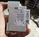
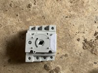
Based upon the below explanation, your situation is looking like DC-PV1 as both 9A strings are in parallel before the isolation switch before inverter. So this switch is only interrupting 18A across 1-2, 3-4.
The 4P rating is for 2 separate circuits. I interpret it as each set of contacts can break 32A from either direction. A second array uses 5-6, 7-8 terminals.
Here's a write-up I found. (Verify it with mfr websites/tech papers.)
During the last thirty years, the industry of solar electricity production has seen an important development. Due to the fact that solar is seen as one of the answers to develop sustainable and renewable energy, the number of photovoltaic installations has increased at an impressive rate.

www.linkedin.com
New IEC Solar standards / Focus on DC-PVX utilization categories

Christopher Briche
NAM Cloud & Service Providers / Electrical Engineer
May 15, 2019
During the last thirty years, the industry of solar electricity production has seen an important development. Due to the fact that solar is seen as one of the answers to develop sustainable and renewable energy, the number of photovoltaic installations has increased at an impressive rate.
In 2017, the world’s total PV capacity has increased by over 4300%, starting at 9.2GW in 2007, reaching up to 404.5GW. There was almost as much solar installed in 2017 as the world’s total installed base in 2012 (100GW).
(Source: SOLAR POWER EUROPE – Global market Outlook 2018-2022)
Solar industry has challenged the conventional approach of energy production and power distribution systems, in terms on electrical performance, operating conditions and environment. PV applications require specific equipment capable of delivering optimal performances under severe conditions.
In 2015, International Electrotechnical Commission has added a new subclause to IEC standard 60947-3 regarding switches, disconnectors, switch-disconnectors and fuse-combination units.
Referenced as
Annex D, the new standard apply to DC switches, disconnectors, switch-disconnectiors and fuse-combination units intended to be used in PV systems.
Since those products are subjected to electrical, environmental and operational conditions that differ from the general conditions, requirements for such devices have been adapted to reflect these new conditions of use.
One the many new requirements concerns the creation of
PV utilization categories. In conventional DC systems, switches for example are chosen for their utilization category such as DC-20, DC-21, DC-22 up to DC-23. PV fields now require the need for
DC-PV0, DC-PV1 and DC-PV2.
These new categories take into account different problematic seen on PV fields such as the emergence of reverse currents, critical currents and significant overcurrent under specific time constant. Those electrical phenomenons may affect the global performance and life cycle of PV strings, string and central inverters as well as battery systems.
Typical applications for those categories are stated in the IEC 60947-3, Annex D standard:
- DC- PV0: Opening and closing a PV circuit to provide disconnection when no current is flowing,
- DC-PV1: Connecting and disconnecting singe PV string(s) where reverse currents and significant overcurrent cannot occur,
- DC-PV2: Connecting and disconnecting PV circuits where significant overcurrents may prevail and where current flow can be in both directions; for example, where several strings are connected in parallel and to the same inverter, or, one or more string with a battery.
During normal operation of a PV field, each switch and fuse in combiner box will see nominal current provided by the PV array downstream of the installation:
Nominal current I1 will flow through Switch 1 in Combiner Box 1:
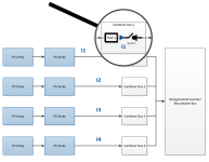
However in the event of an isolation fault in between PV Array and Combiner Box 1, X times the nominal current will pass through Switch 1, which is also called overload current :

For example in the diagram above, Switch 1 in Combiner Box 1 will see Itotal passing throught.
According to IEC standard,
DC-PV2 products shall comply with specific overload testing procedures, such as, opening and breaking
five times (5 cycles),
4 time the nominal current of the switch with a time constant of 1ms (L/R).
Those tests insure that product will function correctly in the event of overload current seen on PV field were traditionally DC-21 would have been used (DC-21 only requires 5 cycles at 1,5 time the nominal current).
As an example a 400A rated load break switch will be subjected to 1600A overload testing in
DC-PV2 whereas in DC-21B it will only be tested at 600A.
Since those scenarios might appear frequently in PV fields, SOCOMEC recommends on using
DC-PV2 products, adapted for these events.
Operational performances on PV product also differ from conventional DC utilization categories. Another example is the number of operations required from a PV load break switch.
Traditionally where DC-21B load break switches were used, the number of operations required by IEC standard was
1000 cycles (making and breaking) for a 400A rated product. For
DC-PV2 utilization category a 400A load break switch is required to perform
5000 cycles, which guarantees a more robust solution.
Annex D of the IEC standard also takes into account the severe environment conditions that products will see on the field. Those conditions are covered by testing the products under severe thermal cycling and climatic tests. Such test includes specific thermal procedures composed of 50 cycles, each consisting of:
- 1 hour at -40°C followed by 1 hour at 85°C,
- After the 50 cycles, product will have to return to room temperature of 25+/- 5°C for a minimum of 3 hours
Product will later be subjected to standard inspection:
- Visual inspection to confirm that there is no distorsion or damage to parts that will affect normal operation and protection,
- One open and close operation to confirm mechanical operation,
- Temperature rise test
- Dielectric test
Other climatic tests are also performed on products according to IEC standard 60947-1, Annex Q, category F which includes:
- Temperature test range,
- Vibration test, according to IEC 60068-2-6
- Shock test, according to IEC 60068-2-27
- Dry heat test, according to IEC 60068-2-2
- Damp heat test, according to IEC 60068-2-30
- Low temperature test, according to IEC 60068-2-1
- Salt mist test, according to IEC 60068-2-52
INOSYS load break switch range has been specially designed to answer to the new requirements seen in photovoltaic industry and will secure your installation in the case of current faults, extreme climatic conditions, as well as other requirements defined for
DC-PV2 utilization categories.

#Switch to Innovation, Switch to INOSYS.