To avoid these ads, REGISTER NOW!

Tapered bushing won't install into pulley

Tedison

Active member
Joined
Oct 24, 2015
Messages
33
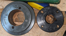
I am attempting to install a tapered bushing/pulley onto a shaft and I cannot get the tapered bushing all the way into the pulley. My understanding is that the pulley should be pulled all the way right to the rim of the bushing. I am finding at least a 1/4 inch gap. Tried tapping it with a soft hammer, a punch, tried using C clamps to draw it closed while snugging the screws. Cleaned the shaft and all mating parts, put a coat of oil on all matching parts. I even tried taking the pulley and bushing off the shaft to see how far I could tap the bushing in and still there was a gap of at least 1/4 inch. This is for a replacement motor for a Walker Turner 16" Bandsaw. The motor has a 22 mm shaft, H-22MM Amec Industrial bushing and B-Section Single Groove Pulley BK34H.


PXL_20251017_220254491.jpgPXL_20251017_220020641.jpgPXL_20251017_220258535.jpgPXL_20251017_220024338.jpg


Attachments

  • PXL_20251017_220246129.jpg
    PXL_20251017_220246129.jpg
    934.9 KB · Views: 4
Last edited:
To avoid these ads, REGISTER NOW!

yellowbox

Well-known member
Joined
Dec 9, 2008
Messages
4,683
Probably doesn't press all the way in , but if it is supposed to, then you'll need to press it in with a press
The kinda press that can remove bearings can be used to Install this
With that much of a gap I bet it isn't made to be pressed in completely like you're describing
You said it is tapered , that explains why it isn't going to go in as far as you think it's going to
 

vrstcv

Active member
Joined
Dec 3, 2020
Messages
31
Location
ne
That looks like one that will stand out from each other . Look at the sides of the hub for size specs. Also tighten the bolts even and not to tight to not split the pully. I speak of this from sad experience.:mad: Yellowbox typed faster than I. But I agree with all but the press. the bolts look to be about 1/4 in or metric =. I repeat do not over tighten!
 
Last edited:

RoninB4

Well-known member
Joined
Jul 22, 2020
Messages
3,594
Location
Under My House
-Tapers are, in some ways, more difficult to apply than a constant diameter bushing. The angles have to match, doesn't take much difference in angle to not mate properly. There's also the problem of measuring one to fit the other, can't whip a micrometer or caliper on the OD/ID to determine whether it's within spec or not. Diameter difference over a determined length is good but how many have the equipment to do that? Diameter where the tapers start also affect flange-to-face contact or gap. Checking the angles can be done with a sharpie and rotating one inside the other, then checking for contact patch. Kinda like checking valves against the valve seat. If the contact patch seems good then that's the important part. Yeah the gap isn't ideal but you can't just continue to crank the bolts in without risking the outer component fracturing. I've had similar tapered bushings that had a gap. I ended up making a spacer that accurately filled the gap under torque and used thread locker on the fasteners. As long as there's a proper lock-up between the tapers (important) you just need to ensure the tapers don't separate. Purchased items don't always fit together like they should anymore. JMO.
 

goldtang

Well-known member
Joined
Feb 11, 2012
Messages
475
Location
Western Australia
My 2 cents, I would clean the paint of both tapers and the bore, don’t use anything that removes metal you could try thinners of acetone and a scouring pad , this should allow it to go in a bit more if the paint is thick
I would not be to worried about a gap , better that than it still slides on the shaft when tight
 

Dodgeboy2020

Well-known member
Joined
Dec 10, 2020
Messages
45
Location
WI
I've installed many of that type of taper lock over the years, when they would make contact is when I was concerned there was a problem. That type in my experience is supposed to have a small gap (should be even all the way around as other have mentioned about making sure its been evenly clamped into place) There are other types of taper lock bushings that are designed to be more of a flush mounting to the face of the pulley but those use a set screw and do not have a flange on the outer surface.
 
To avoid these ads, REGISTER NOW!
OP
T

Tedison

Active member
Joined
Oct 24, 2015
Messages
33
Thanks all! The responses were very helpful, Pulley and bushing are installed.
 

mikegt4

Well-known member
Joined
Sep 12, 2005
Messages
3,275
Location
sw ohio
I installed hundreds of tapered bushing pulleys when I worked in production machinery R&D, the OP's photo looks perfectly normal to me. If the taper bottoms out against the pulley it can't fully compress against the shaft. Tighten the bolts down and your done.
 

larry_g

Well-known member
Joined
Apr 28, 2007
Messages
16,891
Location
oregon
I am attempting to install a tapered bushing/pulley onto a shaft and I cannot get the tapered bushing all the way into the pulley. My understanding is that the pulley should be pulled all the way right to the rim of the bushing. I am finding at least a 1/4 inch gap. Tried tapping it with a soft hammer, a punch, tried using C clamps to draw it closed while snugging the screws. Cleaned the shaft and all mating parts, put a coat of oil on all matching parts. I even tried taking the pulley and bushing off the shaft to see how far I could tap the bushing in and still there was a gap of at least 1/4 inch. This is for a replacement motor for a Walker Turner 16" Bandsaw. The motor has a 22 mm shaft, H-22MM Amec Industrial bushing and B-Section Single Groove Pulley BK34H.

PXL_20251017_220254491.jpgPXL_20251017_220020641.jpgPXL_20251017_220258535.jpgPXL_20251017_220024338.jpg

in either of the two positions shown below. Size M should be assembled in position one. Position 1 Position One is the conventional or standard mounting. Position 2 Position Two (Reverse Mounting) may be necessary in some cases, such as mounting small sheaves with blind holes (not drilled through). Bushing Size Cap Screw Size & Thread Foot Pounds Wrench Torque* JA No. 10 3 SH 14-20 6 SDS 1/4-20 6 SD 14-20 6 SK 5/16-18 10 SF 38-16 20 E 1/2-13 40 F 16-12 50 J 5/8-11 90 M 34-12 150 *For Normal Applications. For Severe (Rock-crusher type) applications these values can be increased by a maximum of 50%. CAUTION: Excessive cap-screw torque can cause sheave and/or bushing breakage. The use of lubricants can cause sheave breakage. DO NOT USE LUBRICANTS IN THIS INSTALLATION! B 3 INSTALLATION 1. Make sure the tapered-cone surface of the bushing and the mating bore of the sheave are free of all foreign substances, such as dirt, excess paint accumulations, metal chips, lubricants, etc. 2. For position one or two (whichever applies), line up the unthreaded holes (C) with the threaded holes (T) and insert cap screws with lock washers engaging only two or three threads. (*a) 3. With key in shaft keyway, slide the looselyassembled unit onto shaft and position for good belt alignment. (*b, *c) Use no lubricants or anti-seize compound on threads or tapered surfaces. 4. Carefully tighten the capscrews alternately and progressively until the tapers are seated (at approximately half the recommended torque). 5. Check alignment and sheave runout (wobble) and correct as necessary. 6. Continue careful alternate and progressive tightening of the cap screws to the recommended torque values shown in the table. Maximum torque should be achieved on each individual bolt only two times in the consecutive tightening. Note: When properly mountecl, there will be a gap between the bushing flange and sheave after the screws are tightened. Caution: Use of Lubricants and/or excessive screw torque can cause breakage. 7. Tighten the set screw, when available, to hold the key securely during operation. (*a) When mounting a sheave on M size bushing, position the threaded jack-apart hole (J) as far from the bushing saw as possible to reduce the possibility of bushing breakage. (*b) When installing large or heavy parts in Position One, it may be easier to mount the key and bushing on the shaft first. Then place the sheave on the bushing and align the holes. (*c) Caution: When mounting on a vertical shaft, provisions must be made, which will positively prevent the sheave and/or bushing from dropping during installation. REMOVAL 1. Loosen and remove all mounting cap screws. 2. Insert cap screws in all threaded jack-screw holds (J). 3. Start with the screws furthest from the bushing saw slot and tighten all jack screws alternately and progressively. Keep turning the screws in small equal amounts until the tapered surfaces disengage.

The above is from the factory installation guide here https://www.amecind.com/pages/catalog And go to the bushings catalogue.

lg
no neat sig line
 
To avoid these ads, REGISTER NOW!
Top Bottom