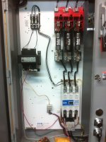
I am new to the world of wiring things and I am in need of some education.
Note: I will add pictures to help clarify what I am dealing with asap as I know my descriptions will most likely not be very good. LOL
We (at work) are installing an air compressor. Instead of using the existing START/STOP switches we have also installed a wall box which will act as the START/STOP control for the compressor. It is a Sullair 40HP series 10B compressor. We moved the transformer from the compressor to the wall box and removed the wires from the hour meter and START and STOP switches on the compressor door.
Currently the wires from the other main components are still plugged into the terminal board as intended. This is where that question of needing some knowledge thrown my way comes in. How exactly does a terminal board function. I see all these wires plugged in from components along the right side of the terminal and I do not understand the logic of their placement.
As per the boss' instruction, I ran a white wire from the (moved) transformer (X2) to the left side of the terminal board also numbered "2". Running the wire from the transformer to the TB2 slot... does that give the whole terminal board power? How do you determine which side of the terminal board to use plug into? He did not explain to me why or how this is supposed to work and he is not around today for me to ask. That is why I am here pestering you guys with the noob questions. Ha! I am an aircraft mechanic by trade so am not mechanically ignorant but I have very little electrical experience to draw from on this kind of thing. If it is mechanical of hydraulic, I am your man, but this is a brain buster to me. So any help would be appreciated. I feel like once I can wrap my head around some of the basics that I am missing, then the pieces will start to fall into place. Thanks in advance.
And I will post pics shortly to help illustrate.
Note: I will add pictures to help clarify what I am dealing with asap as I know my descriptions will most likely not be very good. LOL
We (at work) are installing an air compressor. Instead of using the existing START/STOP switches we have also installed a wall box which will act as the START/STOP control for the compressor. It is a Sullair 40HP series 10B compressor. We moved the transformer from the compressor to the wall box and removed the wires from the hour meter and START and STOP switches on the compressor door.
Currently the wires from the other main components are still plugged into the terminal board as intended. This is where that question of needing some knowledge thrown my way comes in. How exactly does a terminal board function. I see all these wires plugged in from components along the right side of the terminal and I do not understand the logic of their placement.
As per the boss' instruction, I ran a white wire from the (moved) transformer (X2) to the left side of the terminal board also numbered "2". Running the wire from the transformer to the TB2 slot... does that give the whole terminal board power? How do you determine which side of the terminal board to use plug into? He did not explain to me why or how this is supposed to work and he is not around today for me to ask. That is why I am here pestering you guys with the noob questions. Ha! I am an aircraft mechanic by trade so am not mechanically ignorant but I have very little electrical experience to draw from on this kind of thing. If it is mechanical of hydraulic, I am your man, but this is a brain buster to me. So any help would be appreciated. I feel like once I can wrap my head around some of the basics that I am missing, then the pieces will start to fall into place. Thanks in advance.
And I will post pics shortly to help illustrate.