To avoid these ads, REGISTER NOW!

Above 1200 Sq/FT The Action Sports Garage

Wokspaces above 1200 squarefeet.
OP
G

Grant Gunderson

Well-known member
Joined
May 17, 2013
Messages
2,330
Location
Bellingham, WA
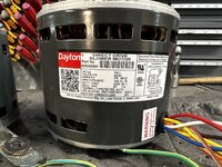
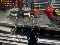
The correct replacement motors for my furnace finally arrived. Im glad I didnt try to tackle that mid winter when I actually need it.
70943666571__714007FE-D278-433B-AA1C-9BD077DDDB32.jpeg
Ended up going with a Dayton motor from Grainger. First step is to shorten the leads and add wire terminals to it.
70943670342__94B7CEEF-0508-44DA-8355-1859FFA9AA5C.jpeg
70943685820__843D0238-39E0-458B-B1CE-988D3C804E3A.jpeg
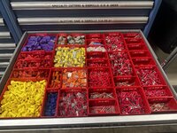
I have a pretty full assortment of wire terminals in the Lista's. Its sure nice not having to run to the hardware store for each project.
IMG_4424.jpeg
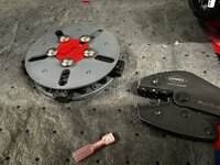
I like using solder loaded heat shrink crimp terminals. They are by far the most reliable I have found. They standard Thomas and Betts are nice but I'm pretty much ready to fully switch to just using these, especially for anything critical. First I crimp them with my Knipex ratcheting crimpers.
IMG_4426.jpeg
They then get heated with the heat gun so the glue filled heat shrink does its job, you then keep heating until the solder melts and flows.
IMG_4428.jpeg
I then use my Brady label maker to print out some heat shrink labels to identify each terminal
IMG_4429.jpeg

IMG_4438.jpeg
They left the housing bolts long on the Dayton motor for some reason.
IMG_4440.jpeg
My Knipex mini bolt cutters quickly fixed that.
 
To avoid these ads, REGISTER NOW!
OP
G

Grant Gunderson

Well-known member
Joined
May 17, 2013
Messages
2,330
Location
Bellingham, WA
IMG_4436.jpeg
The original motor called for a 7.5uF cap.
IMG_4437.jpeg
The new motor calls for a 5 uF cap. Ok the original cap wont work.
IMG_4453.jpeg
testing the original cap it only reads 4.5uF. So chances are thats part of why the motor went out in the first place.
IMG_4526.jpeg
The new start cap tests perfect.
IMG_4446.jpeg
I could finally mount the new motor in to the fan casing after I cleaned 20 years of dust out of it!
IMG_4449.jpeg
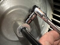
The fan mounts with a squared headed set screw. This is the only scenario I think I have ever used my double square sockets, but they work perfectly for it.
IMG_4452.jpeg

IMG_4527.jpeg
The inducer motor was a direct swap with just 3 sheet metal screws holding it in. With the labeled connections it was easy and quick to get it all hooked back up. 1 project down.
 
OP
G

Grant Gunderson

Well-known member
Joined
May 17, 2013
Messages
2,330
Location
Bellingham, WA
IMG_4536.jpeg
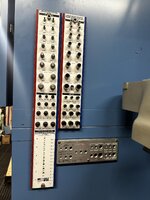
While waiting for the furnace parts to arrive, I relocated my thread gauges to the side of the Lista Cabinets. I mounted them using rivet nuts. I really like this combo as it does 90% of the threads out there. I still have a complete set of thread identifiers on cables that I can take to whatever project I am working on.

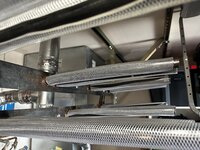
With the furnace project done I then decided to modify the ski rack. It uses 1" steel pipes in parallel to hang the skis by the tips. I had it built 15 years ago. Since that time ski tips have gotten thiner and softer so it doesn't always grip the skis as securely as Id like.
IMG_4589.jpeg
To remedy this I slipped some 1" PVC hose over the pipe. I had to slit the hose lengthwise to get it to fit. I tired heating it and using soap to slide it on, but it was too much of an interference fit.
IMG_4591.jpeg
I then coved the hose with Shrink tubing.
IMG_4594.jpeg
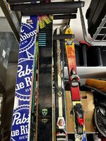
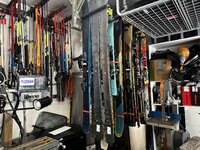
Each set of b are can hold either 4 "narrow" skis or 3 fat skis.
IMG_4596.jpeg
Which reminds me I need to think the quiver out this fall!
IMG_4307.jpeg
I took my son up to Sun Peaks for the opening weekend of the bike park. It was a perfect place for father son trip! He was stoked despite it snowing on us! The 20" Comencal I got him is a great kids bike, but the manitou fork is valved way too stiff for him. I can't get the air pressure low enough for it to properly work for him.
IMG_4564.jpeg
I got him to give me a hand with it back at home.
IMG_4573.jpeg
Everything on a Manitou is *** backwards from a Fox or Rockshocks. Its annoying, but they are dead simple.
IMG_4574.jpeg
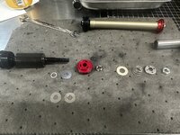
The damper catrige unscrews easily. No shaft clamps required.
IMG_4576.jpeg
L to R is the compression valve stack, the port, and then the check valve. Turns out they use the same valving on this as they do on the adult forks. WTF?
 
OP
G

Grant Gunderson

Well-known member
Joined
May 17, 2013
Messages
2,330
Location
Bellingham, WA
IMG_4579.jpeg
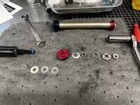
I pulled out two of the 3 compression valve shims.
IMG_4580.jpeg
It all screws back together, but with very little torque on the end nut so the check valve doesn't have too much preload on it. I used some torque seal to make sure it doesn't back off. I then refilled his damper with 2.5wt oil instead of the factory speck 5 wt. That all made a massive difference and it now seems to work perfect for his 40lb body.

Next on the list was working on the lady friends Yeti SB130.
IMG_4495.jpeg
It has the most over complicated suspension system I think Ive ever seen. Especially this floating pivot.
IMG_4497.jpeg
There is no damping at all in the infinity link. It just gets filled with grease via the needle injectors on each tube. All of the pivot bearings were shot. So they all got replaced.
IMG_4506.jpeg
Her Fit4 damper in her 36 had almost no oil in it and when I cycled it you could hear a ton of cavitation, so it needed a rebuild.
IMG_4508.jpeg
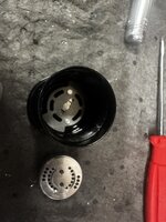
Compared to the Grip 2 damper this is way easier to work on. The adjust can only fit back I the correct way.
IMG_4509.jpeg
This odd looking shim controls what ports get open and when for the lock out feature.
IMG_4510.jpeg
IMG_4511.jpeg
The port then gets dropped in followed by the valve shim stack.
IMG_4512.jpeg
Notice the different sized shims and how they are not in order from largest to smallest. This is how they adjust the initial stroke feel, the pedal support and then the end of stroke feel on the Fit4 dampers since the compression valving isn't externally adjustable.
 
OP
G

Grant Gunderson

Well-known member
Joined
May 17, 2013
Messages
2,330
Location
Bellingham, WA
IMG_4513.jpeg
Valve stack gets dropped back in and the damper screws back together. Unlike the Grip2 damper which self bleeds (it's not a sealed cartridge like most believe) the Fit 4 is a sealed system. So you need to use a suspension syringe to bleed it while cycling the damper. Same idea as bleeding your brakes. Pretty simple to do and you do not need a stupid expensive vacuum bleeder to do it either.

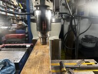
After all of that I was hoping to finish up my shaft clamp project then get back to work on the lathe. However I kept snapping ⅛" End mills. Despite doing some really light cuts and having the y axis locked. Something isn't right. I noticed I was getting some vibrations in the spindle and something sure didnt sound right in the head.


IMG_4606.jpeg
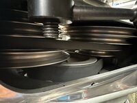
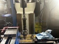
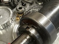
Upon inspection while the spindle was running, The large Drive belt pully in the bottom of this picture had a ton of wobble to it. Thats not good! Time to tear into the head unit. I dont recall replacing the bearings when I rebuilt the Bridgeport when I got it.
IMG_4610.jpeg
First step, unscrew the locking lever handles for the motor and lift it off.
IMG_4611.jpeg
IMG_4612.jpeg
That little pancake motor has some weight to it. The bearings in it still feel good.
IMG_4613.jpeg
I know have access to the drive gear pully. Its top flange is held on by 4 screws.
IMG_4614.jpeg
a #4 hollow ground screw driver is perfect for this.
IMG_4615.jpeg
You can see a lot of rub from the belt.
IMG_4616.jpeg
6 SHCS hold the belt housing to the back gear box.
IMG_4617.jpeg
With those out, the pully housing comes off. Both shafts have a wobble. **** I sure hope I dont need new spindle bearings too.
 
OP
G

Grant Gunderson

Well-known member
Joined
May 17, 2013
Messages
2,330
Location
Bellingham, WA
IMG_4619.jpeg
3 nuts hold the gear box on. I sure like how a ¾ wrench and a hex socket will do just about everything on a Bridgeport
IMG_4623.jpeg
The mounting bolts can easily be removed from the key way. Notice it still has the grease from when I assembled it and it's in good shape. Thats good I guess. However the lock ring has come loose! I must not of gotten the locking tab all the way engaged. Interesting.
IMG_4626.jpeg
The spindle still spins smoothly. The bearings are probably ok, but if I dont replace them now, they will need to get replaced soon. I'll have to see how much they are going to run. Maybe I do the gear box ones now and test it before committing to the expensive spindle set.
IMG_4627.jpeg
The retaining nut for the pully was only hand tight. I know I must have tightened it more than that! It must have vibrated loose.
IMG_4628.jpeg
I used to struggle using pullers getting them lined up properly. Then I bought a set of Posilocks and haven't looked back. Their cage system makes them a hell of a lot easier to use.
 
OP
G

Grant Gunderson

Well-known member
Joined
May 17, 2013
Messages
2,330
Location
Bellingham, WA
IMG_4632.jpegThe woodruff key then gets removed from the shaft. You have to tap it from the bottom otherwise it will bind its self in there. I forgot that and luckily remembered once it started moving! 4 pan screws hold the cover plate on and it can then be removed with a putty knife.
IMG_4636.jpeg

Notice the wear on the gears here. Something wasn't sitting quite right.
IMG_4638.jpeg
The spindle nut gets removed with a hook spanner.
IMG_4639.jpeg
And the lock washer comes off. Can someone remind me of the proper name for this guy?

IMG_4642.jpeg
The clutch shaft seems to be in decent shape. the teeth on the end have some wear, but not enough to warrant replacing.
IMG_4649.jpeg
I then use a pin punch to tap out the pin the fork shifter slides on for the back gear selector.
IMG_4651.jpeg
IMG_4652.jpeg
As a reminder when its set to OUT its fully retracted.
IMG_4653.jpeg
Rotating the selector allows you to remove the fork shifter and gear. I now have access to the larger pully shaft and its lower bearing.
IMG_4656.jpeg
That pulled out pretty easily. The bearing is clearly toast when I spin it by hand.
 
OP
G

Grant Gunderson

Well-known member
Joined
May 17, 2013
Messages
2,330
Location
Bellingham, WA
IMG_4657.jpeg
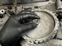
Its easy to press the shaft out on the arbor press.
IMG_4659.jpeg
The clutch shaft bearings on held in place by a large retaining ring.
IMG_4661.jpeg
With that out of the way its easy to press them out with the arbor press and a drift.
71092056800__6D96C8F9-054A-4FA1-86B2-FBEB49DDFC25.jpeg
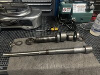
After inspecting the bearings, the large pully shaft uses two 6203 sheilded bearings. I'm going to replace those with sealed ones.
The clutch shaft had two 6208 bearings in it. Turns out those are just radial ball bearings. It's SUPPOSED to have Angluar contact bearings in there. I ordered some SKF 7208 sealed angular contact bearings to replace them. I bet that was the source of the problem. Now the decision to be made is do I order new spindle bearings now, or put it together test it and then decide?
 

Clemson13

Well-known member
Joined
May 30, 2015
Messages
425
IMG_4657.jpeg
Its easy to press the shaft out on the arbor press.
IMG_4659.jpeg
The clutch shaft bearings on held in place by a large retaining ring.
IMG_4661.jpeg
With that out of the way its easy to press them out with the arbor press and a drift.
71092056800__6D96C8F9-054A-4FA1-86B2-FBEB49DDFC25.jpeg
After inspecting the bearings, the large pully shaft uses two 6203 sheilded bearings. I'm going to replace those with sealed ones.
The clutch shaft had two 6208 bearings in it. Turns out those are just radial ball bearings. It's SUPPOSED to have Angluar contact bearings in there. I ordered some SKF 7208 sealed angular contact bearings to replace them. I bet that was the source of the problem. Now the decision to be made is do I order new spindle bearings now, or put it together test it and then decide?
6 years ago, I would have said put it together and test. I was cheap to the point of inconvenience.

Today? No question, put the new spindle bearings in, save a few total hours, and enjoy it at optional performance for a long time. Time is valuable and there are always more projects to spend it on.
 
OP
G

Grant Gunderson

Well-known member
Joined
May 17, 2013
Messages
2,330
Location
Bellingham, WA
The new spindle bearings arrived today. I decided to go with sealed bearings instead of the factory open bearings, so I will be converting from an oil loss lubrication system to a fully sealed grease one. Should make for a cleaner use of the machine. Plus since I dont use it regularly as a machine shop would grease should be better to keep things lubricated.
IMG_4730.jpeg
First, I removed the set screw that locks the quil nose in.
IMG_4731.jpeg
The. quill nose then unthreads.
IMG_4735.jpeg
I then tapped the spindle down out of the quill.
IMG_4739.jpeg
IMG_4741.jpeg
The lock washer tab gets bent back out.
IMG_4743.jpeg
The quill then goes into the vise soft jaws, and a hook spanner removes the lock nut.
IMG_4745.jpeg
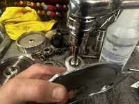
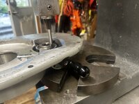
I really should invest in a bearing separator, but two scrap pieces of aluminum angle worked just fine to press the top bearing off.
IMG_4746.jpeg
Note the long spacer is tapered on the end towards the top bearing.
IMG_4747.jpeg
I then used a short piece of steel pipe as a drift to press the angular contact bearing stack and its spacers and dust shield off.
IMG_4748.jpeg
All laid out and ready for a good cleaning with isopropyl.
 
OP
G

Grant Gunderson

Well-known member
Joined
May 17, 2013
Messages
2,330
Location
Bellingham, WA
IMG_4750.jpeg
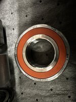
The replacement top bearing is a Sealed NSK 6206DDUCM. The angular contact lower matched set is SKF 7207 BE-2RZP/DBA. these are meant to go back to back.
IMG_4751.jpeg
IMG_4752.jpeg
Notice the difference in the thickness of the outer race. The thicker side faces in a back to back configuration. Typically I always like to install bearings where the side with the marking faces out to make it easier to look up the replacements. That doesn't work for these. On the inner race there is a 093 stamped. I made sure this aligned with the collet setscrew hole for both bearings in the set so that they are properly aligned.
IMG_4753.jpeg
I used the bearing stack spacer as a drift to press the first bearing and the bearing dust cap on.
IMG_4756.jpeg
I then pressed the second bearing on with the inner and outer spacer in-between. Notice the alignment of the V marks. In this matched back to back set, it shows the direction of the principle thrust. I this case facing the end of the spindle with the collets.
IMG_4764.jpeg
The long spacer goes on next with the tapered end facing up. Followed by pressing on the top bearing.
IMG_4766.jpeg
The lock washer goes on next, then the lock nut gets tightened with a hook spacer.
IMG_4767.jpeg
And I bent a tab of the lock washer into the notch on the lock nut to secure it.
IMG_4768.jpeg
I used a block of wood on the mill table and then the Z axis to raise the table pressing the spindle back into place.
IMG_4769.jpeg
My Facom pin spacers worked great to secure the quill nose. Note I grinded down the pin spanner to give more clearance. So that project took less than an hour and I am glad that I did it. The bearings were completely toast. The top spindle bearing was exceptionally bad too. Just need the bearings for the gear box to arrive tomorrow and the mill will be back up and running, and hopefully smoother and quieter than ever.
 
Last edited:
OP
G

Grant Gunderson

Well-known member
Joined
May 17, 2013
Messages
2,330
Location
Bellingham, WA
IMG_4774.jpeg
The bearings for the gear box arrived today. The clutch takes Two SKF 6203-2rsh bearings.
IMG_4775.jpeg
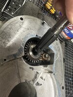
I applied a bit of moly EP grease and pressed them in.
IMG_4776.jpeg
My Park tool bearing drifts really come in handy for removing and installing most small to medium sized bearings.
IMG_5270.jpeg
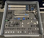
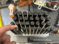
I’m thinking at some point I need set up a similar drawer with all of the various drifts, etc that I have accumulated for use in the arbor press.
IMG_4777.jpeg
Since I am changing from the oil loss lubricant system to a sealed greased one I need to plug the hole for the oiler in the gear box. It takes a 1/8npt plug
IMG_4778.jpeg
IMG_4780.jpeg
The clutch shifter got a very liberal amount of the Moly EP grease
IMG_4781.jpeg
I then pressed in the pin that retains the shifter fork
IMG_4783.jpeg
The shaft also got a liberal amount of grease prior to pressing it in.
IMG_4784.jpeg
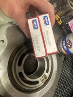
The bill vest uses two angular contact bearings placed back to back. Since these are not critical for spindle runout I’m using a much cheap non matched set. SKF 7208 BE-2RZP
 
OP
G

Grant Gunderson

Well-known member
Joined
May 17, 2013
Messages
2,330
Location
Bellingham, WA
IMG_4786.jpeg
I really wish they would put the bearing info on both the front and back as I always like having it facing out. However in this case the bearings get installed back to back so it won’t be visible once installed
IMG_4787.jpeg
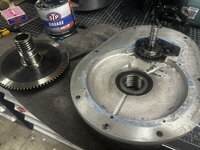
A drift out of a wheel bearing tool set worked perfectly to press the bearings in.
IMG_4791.jpeg
I am big fan of the Whia retaining ring pliers. The notched tips do a better job then most of securely holding the rings.
IMG_4792.jpeg
I then test fit the bull gear. It’s still very close. I think it will benefit from having some brass shim stock to raise it up a bit. I’ll have to see if I can source some in town tomorrow
 
OP
G

Grant Gunderson

Well-known member
Joined
May 17, 2013
Messages
2,330
Location
Bellingham, WA
i picked up some .015 brass shim material this am
IMG_4799.jpeg
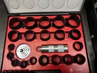
To create the shim I used my Mayhew gasket punch set. This set is nice as you can stack two size’s together to get concentric circles
IMG_4802.jpeg
The shim came out perfect.
IMG_4807.jpeg
A quick test fit and the shin raised the bull gear the perfect amount.
IMG_4803.jpeg
Lock washer and lock but go on next.
IMG_4804.jpeg
I clamped the shaft in my soft jaws and used a hook spanner to tighten the lock nut and then drove the locking tab from the lock washer into place.
IMG_4809.jpeg
I then gave it all a liberal coat of Molly EP grease

IMG_4810.jpeg
The cover gets aligned with its two roll pins and then secured with screws.
IMG_4811.jpeg
I’d normally use a new woodruff key but I didn’t have any on hand so I cleaned up the existing one.
IMG_4813.jpeg
The pilot goes on next and then gets tightened down with the aid of a strap wrench.
IMG_4814.jpeg
Gear box is now done and feels super smooth compared to before.
 
OP
G

Grant Gunderson

Well-known member
Joined
May 17, 2013
Messages
2,330
Location
Bellingham, WA
IMG_4839.jpeg
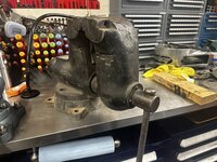
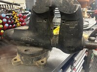
Visiting my dad over in Yakima this weekend I saw a guy on Facebook selling an old vise. I reached out to him and went to have a look. Turns out it was a Wilton C3! I’ve been looking for one in good shape at a tolerable price for years!
IMG_4887.jpeg
I picked up the vise, a 70lb Vulcan anvil and a Riper Whitney Pexto
 

Attachments

  • IMG_4836.jpeg
    IMG_4836.jpeg
    821 KB · Views: 27
  • IMG_4837.jpeg
    IMG_4837.jpeg
    831.4 KB · Views: 26
OP
G

Grant Gunderson

Well-known member
Joined
May 17, 2013
Messages
2,330
Location
Bellingham, WA
IMG_4889.jpeg
Time to get the mill back together first I gave the down feed gears and the spindle splines a very liberal coat of grease.
IMG_4892.jpeg
I then removed the Spindle oil cup.
IMG_4893.jpeg
I replaced it with an ⅛ NPT plug
IMG_4895.jpeg
The long shouldered bolts for the gear head get placed back into their groove.
IMG_4898.jpeg
Gear box gets dropped back on top of the quil housing and locked down with its 3 washers and nuts.
IMG_4901.jpeg
The drive belt gets looped over the spindle
IMG_4902.jpeg
The belt housing gets placed on top next. Spinning the bill gear pully got the drive belt to slip on.
IMG_4905.jpeg
I then reinstalled the upper flange for the drive gear pully with its 4 screws.
IMG_4906.jpeg
The motor then gets placed on top and it’s lock nut levers reinsralled
IMG_4907.jpeg
I the. Used a straight edge to re- align the speed pulleys on the motor.
 
OP
G

Grant Gunderson

Well-known member
Joined
May 17, 2013
Messages
2,330
Location
Bellingham, WA
IMG_4908.jpeg
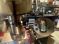
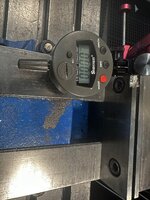
Powered it back up and placed a Starrett indicator on the spindle collet adapter. With the quil retracted at full speed I now have less than 0.000” of run out. That’s damn good!
IMG_4913.jpeg
At full extension I’m getting 0.0005 of runout. I’ll take that. Wish I would have replaced the bearings sooner! When I was originally rebuilding the machine I was a bit intimidated about messing with the spindle bearings based off of what I read on Practical machinist. Truth be told all of the people that make a big deal of it haven’t done it. It’s dead simple to do ( as long as you get the bearing orientation correct) and as I’ve shown here it’s easy to maintain good tolerances or in my case noticeably better.
 
OP
G

Grant Gunderson

Well-known member
Joined
May 17, 2013
Messages
2,330
Location
Bellingham, WA
On to the Wilton 3C vise
IMG_4834.jpeg
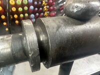
It’s missing the dust cap on the back. I’ll have to see if I can find a freeze plug to fit. Or whenever I finish the lathe I can turn a new one.
IMG_4843.jpeg
I’m also missing one of the pipe jaws and the swivel base is missing the locks and lock cams.
The lock cams are going to be expensive to order if I decide not to make them. Sure wish the lathe was finished right now!
IMG_4846.jpeg
The pipe jaws are just held in place by 1 set screw each. When I put them back in I’m going to drill and tap a hole into the pipe jaws for the set screw to bolt onto to more securely hold them.
IMG_4851.jpeg
The Thrust plate is held in place by 3 screws
IMG_4852.jpeg
I can now unscrew the lead screw from the vise
IMG_4855.jpeg
Look at the massive size difference of it compared to my 6-½” Tradesman! We are in the big boy leagues now.
IMG_4856.jpeg
The dynamic jaw can then be pulled out. It’s F’n heavy! The key way is held in place by two roll pins. I used a brass roll pin punch to drive them out. Notice the special dimpled tip on the roll pin punches.
IMG_4883.jpeg
The machined key is in great shape. Notice the holes must have been hand drilled as they are not centered so it will o my go back in in the correct orientation
IMG_4885.jpeg
This vise has no date stamp on it.
IMG_4859.jpeg
Typically a Wilton has two dowl pins on each side that hold the rear cap on. I’m missing one.
 
OP
G

Grant Gunderson

Well-known member
Joined
May 17, 2013
Messages
2,330
Location
Bellingham, WA
IMG_4861.jpeg
The other is hiding here. On my tradesman I drilled and tapped these for set screws making it easier to remove to grease in the future. I’ll do the same here.
IMG_4862.jpeg
A long Starrett pin punch got the pin out with ease
IMG_4865.jpeg
It’s a grooved dowl pin. Interesting

IMG_4869.jpeg
The long lead screw not is now free to pull out of the end of the vise casting.
IMG_4871.jpeg
I then tapped the end cap off with a long piece of scrap wood.
IMG_4874.jpeg
Notice it’s got an off set bore. So it has to get reinstalled on the correct orientation.

Time to give it all a good scrubbing with brake cleaner and then into some EvapoRust it goes.
 
OP
G

Grant Gunderson

Well-known member
Joined
May 17, 2013
Messages
2,330
Location
Bellingham, WA
IMG_4915.jpeg
On every Wilton vise I’ve come across the thrust plate and the screw has a bit of wear. I have plans to fix this with a thrust bearing.
IMG_4916.jpeg
A file did quick work of deburing and chamfering the edge. This project is going to motivate me to finish the 10EE lathe!
IMG_4924.jpeg
The sand casting is pretty rough.
IMG_4931.jpeg
My Strawberry pattern ******* file should help level things out. It’s really nice having one of the file holders for it to get more leverage

IMG_4934.jpeg
I then used one of these abrasive nylon brushes in my drill to knock the loose stuff off
IMG_4939.jpeg
Curios what this 1 towards the base of the casting ment.
IMG_4945.jpeg
Wilton used two ¼” dowl pins to hold the back. It and rear casting in place. I’m going to replace them with long set screws to make future service easier

IMG_4942.jpeg
First I drove an alignment punch in to make sure it IMG_4946.jpeg
I then used an F drill to bore the hole just slightly larger for the 5/16-18 tap.
IMG_4947.jpeg
I then used a countersink to chamfer the holes.
 
To avoid these ads, REGISTER NOW!
OP
G

Grant Gunderson

Well-known member
Joined
May 17, 2013
Messages
2,330
Location
Bellingham, WA
IMG_4955.jpeg
I then taped the hole. I love my Starrett tap handles!
IMG_4954.jpeg
I then screwed In a 1.5” long set screw and then repeated the process on the other side. When I’m done these set screws will get replaced with stainless ones.
IMG_4959.jpeg
I then used my air die filer to grind the area where the two casting sections meet flat.
IMG_4960.jpeg
IMG_4961.jpeg
IMG_4962.jpeg
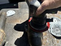
I then used it to smooth out as many of the high spots and rough texture from the sand casting process as possible. This will save me time latter.
Next step is to finish polishing the handle and then machine the castings on the Bridgeport
 
OP
G

Grant Gunderson

Well-known member
Joined
May 17, 2013
Messages
2,330
Location
Bellingham, WA
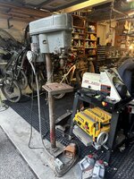
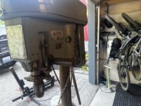
A buddy down I seattle that used to work at the K2 ski factory out on Vashon reached out telling me he had an old Delta Rockwell drill press from the original ski factory that I could have.

IMG_4965.jpeg
it’s in pretty rough shape. It’s a 15-017 and based upon the serial number it’s from 1972

IMG_4966.jpeg
It came out of the resin lab and K2 was apparently using it to mix batches of resin for the skis.
71220145761__6B8B12BF-1EA3-423A-BB16-1543AAA27295.jpeg
So the table is in great shape but it’s caked in old epoxy/ polyurethane. It’s going to be real fun to clean up.
It’s also been modified to run off of a foot switch.

I got a specific idea in mind for doing a restoration on this one, but it’s going to have to wait in line until I can get to it.

Seattle traffic heading back northbound was a ***** and ate up most of my afternoon. Once home I decided to get back to work on the vise. With another project still running in the mill I turned my attention to the handle / screw.
IMG_4970.jpeg
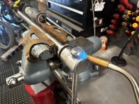
The knobs on the handle are peened on. I tried to heat it up with a blow torch and then tap them off with a pin punch but that didn’t work. I used more heat and tried pressing them off with the arbor press and still no luck.

Once it cools off I’ll have to polish it working around the handle / screw.

IMG_4976.jpeg
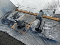
I then decided to blue the non painted parts of the vise to prevent corrosion. Ended up doing a few coats before it got too dark outside. So not much progress today. Hopefully I have more time tomorrow as I want to put the new vise into service asap.
 

Attachments

  • IMG_4978.jpeg
    IMG_4978.jpeg
    836 KB · Views: 15
  • IMG_4967.jpeg
    IMG_4967.jpeg
    714.6 KB · Views: 16
OP
G

Grant Gunderson

Well-known member
Joined
May 17, 2013
Messages
2,330
Location
Bellingham, WA
IMG_4981.jpeg
Here is the handle after a round on the Baldor buffer with the combo scotchbright and sand paper wheels
IMG_4982.jpeg
I then did two different polishing compounds before a final buff
IMG_4984.jpeg
And a final wipe down with some Never Dull.
IMG_4853.jpeg
And here is the before pic. I was pretty impressed I was able to get the hammer marks out of it!
IMG_4992.jpeg
The handle needs a rubber bump on each end so it dose not slam down each time you use it. I figured an o-ring would be perfect. I have a pretty full set so they won’t cost many anything either.
IMG_4995.jpeg
A 210 size oring works perfect. The handle is basically done now.
IMG_4987.jpeg
My McMaster order came today too. Got material for new jaws as well as some brass shins and a Needle Thrust bearing to add to the screw.
IMG_5063.jpeg
I also picked up all new air couplings for the shop. These Milton’s are a big upgrade from the high flow ones I got from
Lowe’s that just haven’t held up.
 
OP
G

Grant Gunderson

Well-known member
Joined
May 17, 2013
Messages
2,330
Location
Bellingham, WA
I took a short break from the vise project to modify my Abbey Suspension bearing press. This one is way nicer than the Park version but Park makes a way better Drift system. Problem is the Park uses a 8mm non hardened shaft and it keeps developing burrs making it very difficult to use. The Abbey uses a ¼ acme thread. Much better but the shaft size is too small to center the Park drifts. So the plan is to modify the Abbey to use a TR8-2 Trapezoid screw.
IMG_5004.jpeg
you can see the size difference in the screws here.

IMG_5007.jpeg
I used the thread for the Abbey press chucked into the jaws on the mill to auto center it for me.
IMG_5013.jpeg
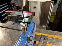
I then drilled it with a 6.2mm bit and chamfered both sides of the hole.
IMG_5014.jpeg
I then used a tap guide and one of my Starrett tap wrenches to thread it.
IMG_5019.jpeg
A quick test fit with the TR8-2 screw and I’m happy.
IMG_5024.jpeg
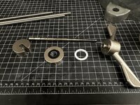
The drive end of the Abby is well made and they use magnets to hold the bushing driver side of the thrust bearing on. Smart.
IMG_5039.jpeg
I used the same threaded rods as before to center it in the mill and then drilled it with a size Q drill this gives just a bit of clearance over the 8mm thread.
IMG_5043.jpeg
And then chamfered both sides of the hole with a countersink.
IMG_5048.jpeg
A small retaining ring holds the Thrust bearing on.
IMG_5050.jpeg
The bearing was bone dry. Abbey makes great tools but for the price they could have at least greased the bearing!
 
OP
G

Grant Gunderson

Well-known member
Joined
May 17, 2013
Messages
2,330
Location
Bellingham, WA
IMG_5057.jpeg
I drilled and chamfered the hole.
IMG_5059.jpeg
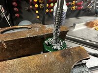
Then tapped it. But I needed more depth than the mill vise provides for this long TR tap. So over to the bench vise.
IMG_5061.jpeg
The Trapezoid tap ***** at clearing chips. I had to back it out a bunch of times to clear the chips out.
IMG_5064.jpeg
I gave the thrust bearing a liberal amount of Super lube grease.
IMG_5073.jpeg
All back together and it now works perfectly with the Oark bearing drifts.
IMG_5074.jpeg
I was going to modify the Park version next as its gander provides more leverage. Since it is already drilled for an M8 thread I need to install a threaded bushing to use the Trapezoid threads.
IMG_5077.jpeg
Unfortunately the bushing Diameter is 22mm and the largest metric endmill I own is 20mm. So this will have to wait until the 22mm mill I ordered arrives.
 
OP
G

Grant Gunderson

Well-known member
Joined
May 17, 2013
Messages
2,330
Location
Bellingham, WA
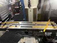
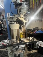
Ok back to the vise. I need to machine parts of it on the mill.
IMG_5079.jpeg
First I pulled the mill vise off and gave the table a good cleaning.
IMG_5082.jpeg
I then stoned it to remove any burrs.
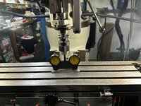
Since I just replaced the spindle bearings and I have the vise off, now is a good time to square up the spindle.
IMG_5085.jpeg
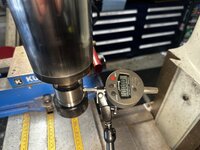
Looks like it’s off .06mm on the x axis I think I can get it better than that.
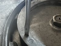
IMG_5086.jpeg
It’s of 0.48mm in the Y direction. That one is easier to adjust so I did it first.
IMG_5091.jpeg
Got it within 0.005mm. I’m good with that!
IMG_5094.jpeg
I then rechecked the X-axis it’s now off by only 0.01mm. I’m going to call that good enough! The Starrett head tram sure makes this process easier!
IMG_5097.jpeg
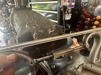
I then placed the vise on the mill table and swept the lower jaw rest and ensured it read 0.000in all the way across.
IMG_5104.jpeg
IMG_5103.jpeg
I then did the same on the face to make sure I had the vise 💯 square.
 

Attachments

  • IMG_5085.jpeg
    IMG_5085.jpeg
    635.5 KB · Views: 5
OP
G

Grant Gunderson

Well-known member
Joined
May 17, 2013
Messages
2,330
Location
Bellingham, WA
IMG_5105.jpeg
I used a flash light to help me line up the pin holes for the vise machine key.
IMG_5106.jpeg
I then installed new roll pins with a roll pin punch so they sat just bellow flush.
IMG_5110.jpeg
I then put the vise together and used a set of ⅜” bolts through both sets of jaws to make sure it was as rigid as possible.
IMG_5119.jpeg
Here is my final setup before machining it. Notice the spring clamp to keep the vise handle out of the way.
IMG_5123.jpeg
I ended up taking 0.100” off of the top of the jaws to clean them up.
IMG_5126.jpeg
That’s enough for one night. More to come.
 
OP
G

Grant Gunderson

Well-known member
Joined
May 17, 2013
Messages
2,330
Location
Bellingham, WA
With the top cleaned up nicely, I switched to a long 5 flute carbide mill
IMG_5129.jpeg
After the first pass you can see how banged up this casting actually is.
IMG_5131.jpeg
0.070” removed latter and it’s nice and clean. It’s amazing how nice this cast iron cleans up. Way better than other castings I’ve machined before.
IMG_5134.jpeg
I took the same amount off of the other side.
IMG_5135.jpeg
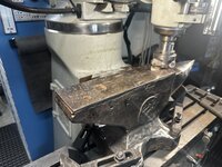
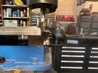
With the jaws done I then slid the head of the mill back to its original position to machine the anvil portion of the vise. It’s very rough.
IMG_5137.jpeg
I typically like to mill with the quill fully retracted but that wouldn’t work here.
IMG_5139.jpeg
Ended up taking 0.125 off, but man did it clean up well.
IMG_5152.jpeg
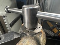
After a lot of head scratching I figured the best way to clean up the screw bore was to extended the ram and angle the turret.
IMG_5142.jpeg
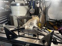
Since the only flat spot on the dynamic jaw is the jaws them selves I rated them in some Starrett blocks. I then used some parallels and some shim stock on the back to get it level. This looks like a simple set up but it took me damn near an hour to get it totally square and centered using an indicator.
IMG_5143.jpeg
I redrilled the center bore to clean up the burrs on it.
 

Attachments

  • IMG_5127.jpeg
    IMG_5127.jpeg
    764.2 KB · Views: 9
OP
G

Grant Gunderson

Well-known member
Joined
May 17, 2013
Messages
2,330
Location
Bellingham, WA
IMG_5145.jpeg
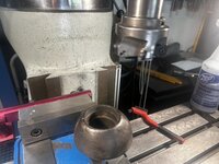
I then used a 2” carbide insert mill to clean up the counter bore. I had to increase its depth to accommodate a thrust bearing.
IMG_5148.jpeg
Time for a quick test fit
IMG_5147.jpeg
Perfectly flush.
IMG_5153.jpeg
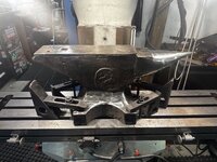
On to the anvil. I thought I had it clamped down well with 4 clamps on it.
IMG_5155.jpeg
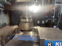
Used the same large mill to clean up the top
IMG_5160.jpeg
I then moved onto the front of the anvil. That’s when the mill caught a high spot and spun the anvil. Well ****. Time to stop and we think my clamping to better accommodate the forces from milling.
IMG_5158.jpeg
Back to the vise I have this ridge left from milling it’s anvil.
IMG_5159.jpeg
So used a strawberry pattern blasterd mill to clean it up and even it out. That’s enough for one night
 

loganb

ALLIANCE MEMBER
Joined
Dec 29, 2011
Messages
5,604
Location
Omaha, NE
Just wanted to say thanks again for continuing to share your projects! I'll never tear down a bike shock, but still enjoy going thru to see your methodology, tools used and drool worthy Lista drawer pics! Definitely interested in how that thrust bearing works out on the Wilton....just picked up a new to me 3.5" swivel jaw and swivel base one and working on cleaning it up and repainting...though the scope of it's overhaul will be far less then you're doing!
 
OP
G

Grant Gunderson

Well-known member
Joined
May 17, 2013
Messages
2,330
Location
Bellingham, WA
Just wanted to say thanks again for continuing to share your projects! I'll never tear down a bike shock, but still enjoy going thru to see your methodology, tools used and drool worthy Lista drawer pics! Definitely interested in how that thrust bearing works out on the Wilton....just picked up a new to me 3.5" swivel jaw and swivel base one and working on cleaning it up and repainting...though the scope of it's overhaul will be far less then you're doing!
Thanks! On every Wilton I’ve come across there has been a fair amount of wear in the thrust plate, so I’m hoping the combination of the thrust bearing and some Brass shims on the other side of the screw’s retaining ring will tighten up any handle play and allow for smoother operation and less play.
 
OP
G

Grant Gunderson

Well-known member
Joined
May 17, 2013
Messages
2,330
Location
Bellingham, WA
I retramed the mill and got it pretty damn close
IMG_5214.jpeg
I then finished machine the anvil.
IMG_5221.jpeg
I then polished the Anvil and the anvil section of the vise with 1k up to 4k sanding pads

IMG_5228.jpeg
Followed by some 3m machine polish
IMG_5227.jpeg
That’s as close to a mirror surface as I can get. You can see the grain texture of the iron in there.
IMG_5231.jpeg
I then reinstalled the vise back on the mill and checked to make sure it’s still in tram. The locator on the bottom of the vise really helps with that.
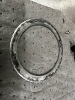
IMG_5232.jpeg
I then cleaned up the rear cone of the vise
IMG_5234.jpeg
So it’s nice and square.
IMG_5235.jpeg
All ready for primer!
IMG_5237.jpeg
I’m using the Omni 2 part epoxy etching primer. Same stuff I used on the lathe project.
 

rbkool

Active member
Joined
Jul 9, 2015
Messages
33
Location
Calgary, Alberta
Awesome stuff, Grant! Love the updates, and hope you are continuing to recover from last winter. Looks like things are trending in the right direction. Your projects are super impressive and I appreciate the time you take to document them here. I worked in the bike industry for several years, in sales and service, but never got into rebuilding suspension components. Seeing them apart on your bench (and back together in one piece!) makes me appreciate those with the skills to do it all the more!
 
OP
G

Grant Gunderson

Well-known member
Joined
May 17, 2013
Messages
2,330
Location
Bellingham, WA
IMG_5238.jpeg
I let the epoxy primer set overnight
IMG_5420.jpeg
I then went to work with the body filler. I started with the fiber filled filler, sanded that down to 80 grit. Then did a layer of bondo and sanded it down to 120. I finally did a layer of glazing putty and sanded it to 240. I’m using Mika abrasives for this. I find they work better than the Festool options for automotive body filler.
IMG_5424.jpeg
I then did a coat of high build poly primer and then wet sanded it to 600
IMG_5426.jpeg
Followed by two sealer coats.
IMG_5430.jpeg
Then the metallic base coat and finally 3 coats of clear.
IMG_5429.jpeg
I’m using the same paint I used on the lathe. It’s all lumabase products. The clear coat is a 3k poly.
 
OP
G

Grant Gunderson

Well-known member
Joined
May 17, 2013
Messages
2,330
Location
Bellingham, WA
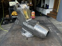
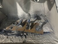
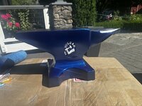
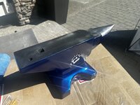
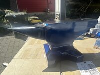
The anvil turned out great. Here is the before
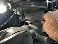
IMG_5154.jpeg
And the after
IMG_5451.jpeg
IMG_5452.jpeg
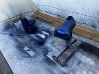
IMG_5453.jpeg
IMG_5454.jpeg
I think I’m going to list it for sale, if it or the welding table sales then I’ll have zero in to the Wilton vise
IMG_5441.jpeg
While I was waiting for the paint on the vise to cure I took the kid for a ride.
IMG_5448.jpeg
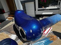
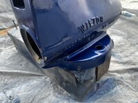
Got back and evidently the wind picked up and knocked the dynamic jaw over and hit the main vise. Thought it was heavy enough not to have moved.
IMG_5450.jpeg
Mother f#<ker. Looks like I got more sanding and painting in my future
 
Last edited:

Tman

Well-known member
Joined
Jan 29, 2006
Messages
543
Location
Black Hills of South Dakota
Wow. Just took the time to read thru this thread. You are over the top organized. Super cool. Impressive bike tool setup, any more I just use the tools at one of my friends shops

I am another bike industry refugee. Been riding since 83, spent half my adult life in shops, helped start a bike company. Now just ride MTB and gravel and work on my stuff as little as possible . Took 29 years off skis (14 away from boarding) and started back skiing 5 years ago during my divorce.

Also forgot to add, I have the same issues with my right hand. OK for now but have always known I need to have it looked at. Ergon Cork grips make it so I can ride
 
Last edited:
OP
G

Grant Gunderson

Well-known member
Joined
May 17, 2013
Messages
2,330
Location
Bellingham, WA
IMG_5644.jpeg
Round two on the paint. Made a more stable base for the dynamic jaw this time. As much as it sucjs having to paint it twice, it allowed me a chance to perfect the body work.
IMG_5648.jpeg
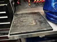
My work bench corner is starting to look a bit like Swiss cheese after my previous two vises.
IMG_5641.jpeg
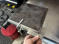
So I picked up some ¾” steel plate. First job was to square up the edges
IMG_5646.jpeg
I then gave the top edge a ⅜ radius
IMG_5652.jpeg
Got the plate in position and squared up and clamped it in place
IMG_5653.jpeg
I then used a ⅝ transfer punch to mark the existing hole locations
IMG_5656.jpeg
To keep everything clean looking I drilled and tapped four blind holes. The tap guide in the
Ill was a big help to get the bottoming tap started. My large Starrett tap handle made it pretty easy too
IMG_5650.jpeg
My original plan was to use the swivel base, but this vise is so tall on my workbench I decided against it. If I ever find a good used rotary table for the mill maybe I’ll make a low profile version. That being said I rarely rotated the previous vises so I’m going to mount it with out it. I used a transfer punch to mark the hole locations. Those also got drilled and tapped blind
IMG_5661.jpeg
I then cleaned off the mill scale and then blued the base.
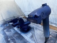
IMG_5663.jpeg
Two mount the vise I made some custom bolts using some ⅝-11 all thread and some red thread locker.
 
OP
G

Grant Gunderson

Well-known member
Joined
May 17, 2013
Messages
2,330
Location
Bellingham, WA
IMG_5664.jpeg
I then bolted the vise to the plate
IMG_5666.jpeg
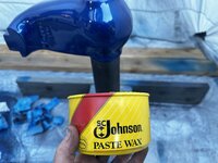
For the dynamic jaw shaft I decided to try some paste wax instead of super lube. We will see if it works or if I go back to using super lube.
IMG_5667.jpeg
Got the dyamic jaw slid into place. It’s f’n heavy.
IMG_5669.jpeg
I decided a thrust bearing would be a good idea on the screw. Decided to go with the needle bearing. If it gives me issues Ill replace it with the bronze oild washer
IMG_5670.jpeg
IMG_5672.jpeg
I gave the screw a very liberal coat of super lube
IMG_5676.jpeg
I cleaned up the 10-32 thrust plate holes with a tap and installed it with new stainless screws with a coat of Tef-gel
IMG_5680.jpeg
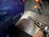
I then used a thread chaser to clean up the threads for the rear set screws
IMG_5682.jpeg
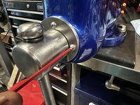
Once the stainless set screws where in position to hold the rear nut in place I locked them in position with some set screw retainers.
 

Attachments

  • IMG_5669.jpeg
    IMG_5669.jpeg
    830.9 KB · Views: 7
To avoid these ads, REGISTER NOW!
Top Bottom