To avoid these ads, REGISTER NOW!

Above 1200 Sq/FT The Action Sports Garage

Wokspaces above 1200 squarefeet.
OP
G

Grant Gunderson

Well-known member
Joined
May 17, 2013
Messages
2,330
Location
Bellingham, WA
Loving all the bike and machining content! What chain guide did you use on your son's bike? My son has a 20" Specialized that has been dropping the chain a lot as well and I think I'll need to put a guide on it. Thanks!
I picked this one up for him
https://www.fanatikbike.com/products/we-are-one-arrival-chain-guide

I can’t believe how expensive they have gotten. I must have thrown a ton of those away back in the day when they used to be dirt cheap. It helps significantly, but he still drops it on occasion. Unfortunately I don’t think the bike has the best chain line on it.
 
To avoid these ads, REGISTER NOW!
OP
G

Grant Gunderson

Well-known member
Joined
May 17, 2013
Messages
2,330
Location
Bellingham, WA
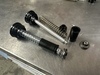
with parts on hand time to rebuild the fork.
IMG_7643.jpeg
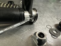
The lower bushing for the Push AC3 unit actually uses a standard DU bushing. The arbor press made quick work of pressing the old one out and the new one in with my Abbey DU bushing drifts.
IMG_7646.jpeg
The new bushing got a liberal coat of Slickoleum
IMG_7647.jpeg
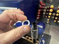
I decided to add some plastic washers on either side of the bushing to make the spring quieter. It also reduce the top out clunck.
IMG_7648.jpeg
IMG_7650.jpeg
I also added a rubber one as well to make the top out absolutely minimal.
IMG_7654.jpeg
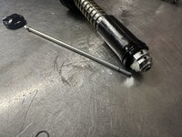
Using brass shaft clamps I reinstalled the foot stud.
IMG_7658.jpeg
Flipped it over and added a plastic washer above the negative spring to quiet it.
IMG_7659.jpeg
Installed the base for the main spring
IMG_7660.jpeg
The plastic bushing for the main spring just snaps on.
IMG_7662.jpeg
Gave it a very liberal coat of slickoleum and back into the stanction it goes.
 
OP
G

Grant Gunderson

Well-known member
Joined
May 17, 2013
Messages
2,330
Location
Bellingham, WA
IMG_7665.jpeg
Main spring and it’s preload cap gets dropped in.
IMG_7667.jpeg
And the AC3 top cap gets torqued on. Spring side is now done other then adding bath oil.
IMG_7668.jpeg
Since the shaft for the compression section of the damper is so worn I’m replacing it as a unit with the new VVC version.
IMG_7670.jpeg
Notice the new butterfly valve adjuster here. This is the only difference between the CVC and the previous version. Supposedly it gives more compression adjustment range…
IMG_7673.jpeg
The low speed compression adjustment still uses a plain old needle valve.
IMG_7674.jpeg
This is the compression valving stack out of the old unit. These shim valves work by oil pressure deflecting the spring shims. So you just change the valving by changing how the shims are configured, their thickness and OD, and their orientation. Ie a pyramid stack or a straight stack as seen here.
IMG_7675.jpeg
On to the rest of the damper. The main damper seal is here. I only use brass o-ring tools as you do not want to scratch the aluminum seats.
IMG_7676.jpeg
The Grip2 uses a modified open bath design unlike the sealed bladder dampers in the FIT4 units. The Grip2 is self bleeding because of this. However for it too all work their is a one way oil seal here that has to go in the correct direction here. Flat side faces up. Cup side down.
IMG_7677.jpeg
A brass oring spoon pushes the new ring into place.
IMG_7679.jpeg
Here is the needle portion of the rebound valving. It just unscrews and has an inner and outer oring.
 
OP
G

Grant Gunderson

Well-known member
Joined
May 17, 2013
Messages
2,330
Location
Bellingham, WA
IMG_7683.jpeg
the outer oring is a ***** to get on as it’s very tight. I actually snapped the one from the kit. Luckily Fox publishes the specs and I had a bunch on hand.
IMG_7682.jpeg
Here is the ball detent for the low speed rebound adjustment.
IMG_7680.jpeg
A long brass rod pushed it out. I then flushed it with suspension clean.
IMG_7681.jpeg
A dab of slickoleum to hold the detent ball and spring in place and it just slides back in.
IMG_7684.jpeg
The damper foot has a inner and a outer static oring
IMG_7685.jpeg
These very rarely leak so most likely don’t need to actually be replaced.
IMG_7688.jpeg
I’d highly suggest not breaking down the rebound high speed valve shim stack. It’s a ***** to reset but I like a challenge. I used to Snapon low torque wrenches.
IMG_7691.jpeg
That’s the valve stack all laid out. It’s simple.
IMG_7695.jpeg
Here you can see how the valve shims form a pyramid. This progressively changes the oil flow rate.
IMG_7697.jpeg
To reinstall it I clamp a 7mm wrench in the vise.
 
OP
G

Grant Gunderson

Well-known member
Joined
May 17, 2013
Messages
2,330
Location
Bellingham, WA
IMG_7699.jpeg
Set the rebound valve stack on it and torque it to spec
IMG_7700.jpeg
The adjuster rod gets assembled
IMG_7701.jpeg
That gap is the adjustment range.
IMG_7702.jpeg
The foot gets installed on to the rebound shaft.
IMG_7703.jpeg
Flip it over and drop in the adjuster shafts
IMG_7705.jpeg
Then slide the main seal head on
IMG_7706.jpeg
The rebound valve head gets torqued on.
IMG_7711.jpeg
The fun part is setting the preload on the butterfly valve. It’s done using a 0.030 shim under the butterfly and then torque the top nut on
IMG_7713.jpeg
It’s set to 3cNm. So gas to be done with a micro torque limiting driver. This is by far the most precise adjustment I’ve ever seen in suspension.
With that done. Just fill the main tube with 5wt oil. Cycle the rebound shaft a few times. Top off with oil and screw in the compression valve unit and it’s done. It’s self bleeding.
IMG_7730.jpeg
Reinstalled the fork and wheel then used this special laser alignment unit to align the handle bars to the center of the tire.
 
OP
G

Grant Gunderson

Well-known member
Joined
May 17, 2013
Messages
2,330
Location
Bellingham, WA
Since it was ******* rain my buddy stoped by for some suspension work.
IMG_7714.jpeg
His float X was getting crazy hot on decents and sounded like ****. Pulled the air can. Cycled it and you could hear it cavitate like crazy.
Two set screws hold the cover plate on.
IMG_7715.jpeg
A pin spanner then unscrews the main seal head.
The shaft was full of foamy oil.
IMG_7717.jpeg
A 15mm socket removes the valve head stack. Talk about simple.
IMG_7718.jpeg
Replaced the main shaft seal in the seal head and gave it a bunch of slickoleum to line it.
IMG_7721.jpeg
Refilled it with oil and bleed it with a syringe and an old Rock Shock reverb bleed tool. Set the IFP height then pressurized the ifp chamber. Cycled the shock and no cavitation. Replaced air can and it was good to go. Only took 10 minutes too.

IMG_7735.jpeg
Picked my son up and spent the afternoon building legos with him.
 

ebarker9

Well-known member
Joined
Oct 1, 2010
Messages
85
This is really cool to see. I've done fork lowers service, swapped out air springs and dampers, converted to/from coil, air can service, but never ventured beyond that. The investment in tools and time never quite made sense given the service intervals for dampers and cost to send them out periodically, but I'm still curious. I had a brand new Float X making horrendous knocking sounds on high speed compression and it did kind of drive me nuts to have to send it out for warranty service (and pay for shipping!), although that's the right move with a new product regardless.
 
OP
G

Grant Gunderson

Well-known member
Joined
May 17, 2013
Messages
2,330
Location
Bellingham, WA
This is really cool to see. I've done fork lowers service, swapped out air springs and dampers, converted to/from coil, air can service, but never ventured beyond that. The investment in tools and time never quite made sense given the service intervals for dampers and cost to send them out periodically, but I'm still curious. I had a brand new Float X making horrendous knocking sounds on high speed compression and it did kind of drive me nuts to have to send it out for warranty service (and pay for shipping!), although that's the right move with a new product regardless.
I'm hoping the by showing the process people will see that it's not that difficult to service the dampers.... basically just replacing o-rings and bleeding them is not that much different then bleeding brakes.

Tool wise, it's pretty simple. The Park cone wrenches will do 90% of it and they serve as a poor mans Crowfoot too. A good set of O-ring tools is essential and a decent set of shaft clamps is all that you really need.
 

Clemson13

Well-known member
Joined
May 30, 2015
Messages
425
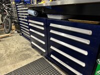
Beautiful Lista cabinet. I love the colors. I have been wanting to convert my whole shop over to a hammered blue finish like tools used to come in.

I haven't bought any Listas yet, used to not have the funds. Now that I do, I have no idea what the right way to value them is. Is a decent deal around 100$ a drawer or so?
 
OP
G

Grant Gunderson

Well-known member
Joined
May 17, 2013
Messages
2,330
Location
Bellingham, WA
Beautiful Lista cabinet. I love the colors. I have been wanting to convert my whole shop over to a hammered blue finish like tools used to come in.

I haven't bought any Listas yet, used to not have the funds. Now that I do, I have no idea what the right way to value them is. Is a decent deal around 100$ a drawer or so?
Thanks. I think $100 a drawer is a good ball park here in the PNW. Wider / deeper drawers increase the costs as does higher drawer counts.

found both the vidmars for only $200 but they took a bit of work.

The last one I picked up for way less than $100 a drawer and ended up not costing me anything out of pocket after I sold my anvil. Being willing to paint them sure helps in keeping the costs reasonable
 
OP
G

Grant Gunderson

Well-known member
Joined
May 17, 2013
Messages
2,330
Location
Bellingham, WA
Finished the apron for the lathe around 11pm last night. Head out for a bike ride this am and come home to a pool of water by the garage door. Wtf? Trace it all the way to the back wall of the garage
IMG_8065.jpeg
It’s coming from the recirc line for the hot water. I’ve had 3 home insurance claims in 3 years from pin hole leaks in this line… always in the ½” elbows and in the damn wall.
IMG_8061.jpeg
This time it’s in the middle of a pipe run. Wtf? At least it’s outside of the wall.
IMG_8067.jpeg
Decided enough with the recirculating pump and cut it out.
IMG_8070.jpeg
Luckily I keep a pretty good assortment of pipe fittings in hand and had everything but solder (when did it go to $55 a roll? I thought it was always $10-12?) to fix it.
IMG_8083.jpeg
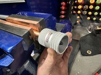
Used my rigid deburing / remeing tool on all of the pipe sections
IMG_8076.jpeg
Cleaned all of the matting surfaces with my pipe brush
IMG_8077.jpeg
Then coated all of the matting surfaces with flux
IMG_8079.jpeg
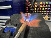
I used a flame guard blanket to protect the vise and heated the pipe with the blow torch.
IMG_8080.jpeg
Been a while since I soldered. The first fitting for the pipe thread was too cold. Notice how thick the solder is around it. I then did a better job of getting the next fitting to temp and notice how much thinner the solder flowed. Way better
IMG_8085.jpeg
It took me years to learn to remember the right direction to install pipe tape on threads.
 
OP
G

Grant Gunderson

Well-known member
Joined
May 17, 2013
Messages
2,330
Location
Bellingham, WA
IMG_8086.jpeg
Old pipe with pump to new pipe in 30 minutes and saved me $750 by not calling a plumber!

So according to reading the manual the recirc pumps are supposed to have a safety pressure release valve on them. It was installed without it so I’m guessing it was on occasion over pressuring the line. I put a pressure gauge on and have 45 psi in the line with out the pump. Also looks like recommended line for recirc should be ¾” not the ½” that I have. Hopefully leaving the pump out fixed the problem for good
 
OP
G

Grant Gunderson

Well-known member
Joined
May 17, 2013
Messages
2,330
Location
Bellingham, WA
I've been spending a bit of time with my son on the bike whenever I have him.
IMG_8707.jpeg
It's been really cool to see how far he has progressed this summer on his little 20" wheel bike. I'm going to need to pick up a 24" full suspension for him this spring!
IMG_8728.jpeg
We ended up having a pretty wet day of full rain on my birthday, so we decided to watch a you tube video on doing wheelies and then make a stand so he can practice. He loved using the impact driver to drive the screws in. I couldn't think of a better way of spending my birthday if we couldn't go for an actual ride.
IMG_8729.jpeg
Happy kid, complete with is own safety glasses
IMG_8750.jpeg
It didnt take him long to get the hang of it. The idea is the scrap wood we screwed together stabilizes the bike, and the old climbing rope is a leash to keep the bike from tipping over backwards. This way he can practice getting a feel for lifting the front end up and getting comfortable with the balance point.

Screenshot 2023-10-21 at 11.14.14 AM.png
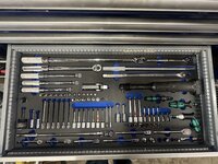
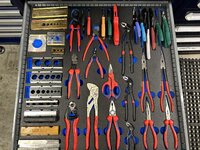
Ive been using toolbed.de for years now for organizing my tool boxes. There foam holds up really well and its really easy to clean if you do get oil / grease on it. I like these guys as they have a full library of tools scanned into their data base, So you just look up your tools part number and you can import it into your own custom layout. Not cheap, but it is about the same cost as a good set of socket rails per drawer and you can actually fit way more stuff in, then if you used prefconfigured socket rails etc. I placed a pretty big order with them to set up the 40" Lista and to redo a few of the Vidmar drawers. The nice thing is you can just copy and past the layout into a new one, and then reconfigure vs. import everything all over again, so changing layouts its pretty easy other than the financial pain to the wallet.
IMG_8827.jpeg
I started to fill the drawers up and realized I made a mistake on my ½" drive drawer and left out a socket. ****.
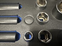
IMG_8828.jpeg

So I grabbed my mayhem hole punch set and found the correct size.
IMG_8829.jpeg
I twisted it in and it made a perfect cut. Problem solved. I have a few tools not in their system that I'll need to hand cut in. I did have a few they didnt list, but they were able to track down on their end and scan and add to the library for me. Nice service.
 
OP
G

Grant Gunderson

Well-known member
Joined
May 17, 2013
Messages
2,330
Location
Bellingham, WA
So here is the new layout for the 40" Lista
IMG_8833.jpeg
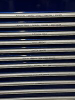
The top deep drawer is going to get left for holding personal protection stuff such as my respirator, safety glasses, extra nitrile glove boxes etc. The second drawer down is my most common used measuring and layout tools, plus picks, knifes, tweezers etc.
IMG_8834.jpeg
Bellow that is my bearing press and all of its drifts, my metal chisels, and various drifts, punches and bench block.
IMG_8835.jpeg
Next is my electrical tool drawer with wire strippers, pin terminal tools and various crimpers
IMG_8836.jpeg
Then my metric wrench drawer
IMG_8837.jpeg
followed by the SAE drawer
IMG_8838.jpeg
and then my Crowfoot, and various hook and pin spanners. I'd ideally have this bellow the ½" drawer but it seemed like a waist to put such low profile tools into a deeper drawer and I really dont want to reconfigure all of the drawers in the Lista.
IMG_8839.jpeg
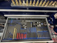
Next is all of my torque tools, ratchets and hex and Torx tools
IMG_8840.jpeg
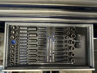
My ¼ and ⅜ drive sockets. The sockets on the right are all specific for bikes, and include a full range of BB sockets and drive sockets for E-bikes plus dedicated sockets for suspension work.
IMG_8841.jpeg
and finally my ½" drive tools. I still have 4 drawers left in the 40" lista so thinking about moving my automotive and plumbing tools into it. Still not sure what I will do with my machining tool drawers as well as the tools specific to the lathe.
IMG_8831.jpeg
I then started In on the Vidmar's. **** my top drawer that I wanted to put my pliers in wont fit. Gotta think if I want to bump them down a drawer or change the drawer layout in the cabinet.....I need to think about it for a bit.
 
OP
G

Grant Gunderson

Well-known member
Joined
May 17, 2013
Messages
2,330
Location
Bellingham, WA
IMG_8869.jpeg
I got the list drawers all labeled. Then moved on to the Vidmars

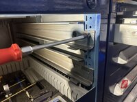
I decided to flip flop the top two drawers. Here you can see the suspension frames for the drawers. These are what give the Lista / Vidmar cabinets so much more strength over Snapon etc.
IMG_8844.jpeg
The Vidmar uses a slightly different rail system then Lista. On the Lista their is locking tabs that hold the rails in place front and rear. On the Vidmar it’s a locking tab in the back and a single screw in the front. It’s splitting hairs but now that I own two vidmars and 3 Listas I feel the Lista cabinets are slightly more refined and I like their drawer handles better.
IMG_8879.jpeg
I flipped the top two drawers on the right cabinet as well so it’s all symmetrical.
IMG_8871.jpeg
The top left Vidmar is my plier drawer and vise jaws

IMG_8872.jpeg
Next down is my bike specific tools. I’m using Kaizen foam for these as toolbed doesn’t have them in their library.
IMG_8873.jpeg
Bike suspension service tools

IMG_8874.jpeg
Headset tools.
IMG_8875.jpeg
Top right Vidmar is my file drawer. I still need to get 3 more handles.
IMG_8876.jpeg
Brake tools and tire sealant injector
IMG_8877.jpeg
Pullers. Still undecided if they are going to live here or not. Nice thing is I have extra drawers now so need to think a bit about the layouts.
 
OP
G

Grant Gunderson

Well-known member
Joined
May 17, 2013
Messages
2,330
Location
Bellingham, WA
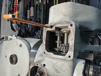
The powered down feed on the Bridgeport has been giving me some issues. I think I got it narrowed down to the Down / Neutral / Up pull out rod. I didnt take pics of pulling the speed select cover or removing the locking set screws but you will get the idea of what I am doing anyways.
IMG_8924.jpeg
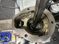
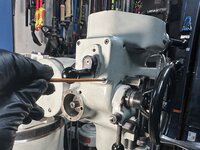
First step is to pull the motor it only has two locking bolts holding it on.
IMG_8926.jpeg
I then removed the draw bar. The Pully and gear boxes can then be removed as a single unit. Its just Threee ¾" nuts that hold it on.
IMG_8927.jpeg
That was easy and not too heavy either.
IMG_8931.jpeg
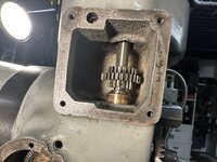
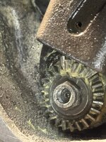
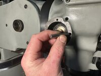
The cradle that engages / disengages the power feed for the quill needs to come out next. I used a piece of wood to wedge the gears and then unscrewed the thin locking nut. Then pulled the spring pin from the selector handle and removed that assembly.
IMG_8932.jpeg
Cradle is out
IMG_8933.jpeg
Followed by its shaft. I then removed the set screws that lock the other gear shaft in place
IMG_8934.jpeg
and tapped that shaft up
IMG_8935.jpeg
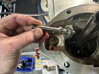
That clutch gear is what changes the speed ratio for the power feed. the previous shaft we pulled is how power is transferred to it.
IMG_8936.jpeg
This is the clutch shaft assembly for the up / N / down feed. with the previous shaft up and out of the way and the handle / front gear pulled off, it just rotates counter clockwise and then pulls out.
IMG_8937.jpeg
My selector knob was bent so I am replacing it with a new one.
 
OP
G

Grant Gunderson

Well-known member
Joined
May 17, 2013
Messages
2,330
Location
Bellingham, WA
IMG_8938.jpeg
This dimpled shaft is the new part I am putting in. The old one was bent before I bought the machine but I thought it was good enough, turns out it wasn't and it ended to be replaced. Those dimples are for the ball detent.
IMG_8940.jpeg
With the assembly supported in Vee blocks I use a Brass roll pin punch to remove the spring pin. Note how on roll pin punches there is a dimple to center the punch in the pin.
IMG_8941.jpeg
Pin is out.
IMG_8943.jpeg
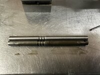
The old shaft is on the bottom. It is only ever so slightly bent. You can see how that was causing it to wear and bind on the left end.
IMG_8944.jpeg
Before I replaced the shaft, I cleaned up the inside of the shifter clutch. Its now Butterly smooth when sliding on the shaft.
IMG_8946.jpeg
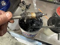
Since I converted my quill to sealed bearings, I no longer am using the oil loss lubrication system, so I gave the parts a coating of moly grease.
IMG_8949.jpeg
The shaft slides back in with a slight twist clock wise to engage the worm gear.
IMG_8947.jpeg
IT gets locked in place with a ¼-20 dog point set screw
IMG_8948.jpeg
and the Bridgeport standard locking hollow set screw.
IMG_8953.jpeg
I then reinstall the power feed shaft, as well as mesh the gears for the speed clutch shaft and engage it with the lower gear on the up / down clutch shaft.
 
OP
G

Grant Gunderson

Well-known member
Joined
May 17, 2013
Messages
2,330
Location
Bellingham, WA
IMG_8955.jpeg
The gears get a coating of moly grease.
IMG_8956.jpeg
The front bevel gear for the up / down feed clutch slides onto the shaft
IMG_8957.jpeg
Followed by the quill knockout. You can see my machine is getting some wear with the paint I used. really wish I had used the same stuff I used on the lathe on it.
IMG_8968.jpeg
The control knob gets installed and I then rotate the shaft and install the small machine key in it,
IMG_8969.jpeg
I then rotate the shaft again so I can see the hole for the ball detent. I then pull the inner shaft out to expose the middle detent.
IMG_8971.jpeg
The detent collar then slides on
IMG_8972.jpeg
I lubed the bal with way oil and dropped it in
IMG_8974.jpeg
The spring gets installed into the cap screw and then it gets snugged down.
IMG_8975.jpeg
A standard set screw then locks the collar on by applying direct pressure to the machine key under it.
IMG_8976.jpeg
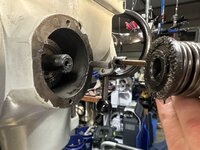
Looking into the top of the quill I need to reinstall the cradle
 
To avoid these ads, REGISTER NOW!
OP
G

Grant Gunderson

Well-known member
Joined
May 17, 2013
Messages
2,330
Location
Bellingham, WA
IMG_8977.jpeg
Cradle is back in
IMG_8982.jpeg
I then can torque down its locking nut
IMG_8983.jpeg
By using the fine feed handle to hold the gears I can then torque the nut on.
IMG_8985.jpeg
The shaft of the selector gets dropped into the craddle
IMG_8986.jpeg
I can then install the selector shaft assembly.
IMG_8987.jpeg
It is held in by 3 SHCS
IMG_8988.jpeg
The selector knob is then retained by a spring pin. I then checked all of the gear functions manually
IMG_8990.jpeg
and then locked the power feed shaft in place with a dog point set screw followed by a hollow locking set screw
IMG_8991.jpeg
The speed select clutch fork gets engaged with its clutch gear then it gets held in place by 4 SHCS.
 
OP
G

Grant Gunderson

Well-known member
Joined
May 17, 2013
Messages
2,330
Location
Bellingham, WA
IMG_8994.jpeg
I then placed a new external retaining ring on the power feed shaft clutch
IMG_8997.jpeg
I then inserted its pin and spring
IMG_8999.jpeg
The clutch gets aligned with the machine key slot in the shaft and slides on
IMG_9001.jpeg
Its cover then gets retained with two shcs
IMG_9002.jpeg
The lever that stops the power feed was bent. This seems to be quite common. I replaced it with a new one. The small set screw in it sets the sensitivity so I gave it set to be very sensitive so ideally won’t bend another one. We will see
IMG_9005.jpeg

IMG_9004.jpeg
Its just retained by the single threaded pin here
IMG_9007.jpeg
I then dropped the gear box back on. Secured it with its 3 nuts followed by the motor. Powered it up and tested the power feed. It’s now smooth as butter!
 

legenddc

Well-known member
Joined
Aug 19, 2012
Messages
1,074
Your work is always amazing. Whether it's photography, working on bikes, shop projects or time spent with your kid. Your tools in the foam setup is drool-worthy. Every time you post it I start looking at all sorts of Snap-On, Wera, Knipex, etc.

Wondering if you could share any of your favorite resources for bike research and bike repair? I'll be in the market for a bigger bike for my son (6) and myself so I can ride with him. Still hoping to get my daughter (8) willing to try again. I'm sure between 3-4 bikes I'll be in for a few repairs, especially if I pick up some used ones.
 
OP
G

Grant Gunderson

Well-known member
Joined
May 17, 2013
Messages
2,330
Location
Bellingham, WA
Your work is always amazing. Whether it's photography, working on bikes, shop projects or time spent with your kid. Your tools in the foam setup is drool-worthy. Every time you post it I start looking at all sorts of Snap-On, Wera, Knipex, etc.

Wondering if you could share any of your favorite resources for bike research and bike repair? I'll be in the market for a bigger bike for my son (6) and myself so I can ride with him. Still hoping to get my daughter (8) willing to try again. I'm sure between 3-4 bikes I'll be in for a few repairs, especially if I pick up some used ones.
Thanks!

I don’t know of that many good how to resources as I’m self taught. I’d start with the Parktool site. A good set of hex / torx keys are a must and a set of Felco C7 cable cutters will get you sorted for most basic repairs.

My son is currently on a 20” commencal and it’s been a great bike for him. I’m. Starting to shop for a 24” full suspension for him for his 7th birthday next spring. I think having the right bike and a good tow strap really helps with getting the kids into it.
 

manbike26

Well-known member
Joined
Sep 23, 2015
Messages
224
Location
Boise ID USA
Thanks!

I don’t know of that many good how to resources as I’m self taught. I’d start with the Parktool site. A good set of hex / torx keys are a must and a set of Felco C7 cable cutters will get you sorted for most basic repairs.

My son is currently on a 20” commencal and it’s been a great bike for him. I’m. Starting to shop for a 24” full suspension for him for his 7th birthday next spring. I think having the right bike and a good tow strap really helps with getting the kids into it.
@legenddc Grant's recommendation of the Park tool site (and their youtube channel) is a great one. I'd also add in that they sell a "Big Book of Bike Repair" if you like print better. Todd Downs wrote a book for Bicycling Magazine many years ago that was also very good.

Finally, if you're in the mood for a trip to a cool town...check out United Bicycle Institute in Ashland OR or Appalachian Bicycle Institute in Asheville NC.
 

legenddc

Well-known member
Joined
Aug 19, 2012
Messages
1,074
Thank you both. I went to the Parktool Youtube page and apparently I had already watched a video there on replacing a tire.

Unfortunately I think our kids are out of the free bike phase as the larger ones tend to be kept longer. We all keep passing bikes around the neighborhood as kids outgrow them. I'll keep my eyes out for used bikes over the winter and see if I can't find a good bike and fix it up.

@manbike26 - I can assure you another trip to Asheville would result in too many brewery visits to be riding a bike.
 
OP
G

Grant Gunderson

Well-known member
Joined
May 17, 2013
Messages
2,330
Location
Bellingham, WA
Thank you both. I went to the Parktool Youtube page and apparently I had already watched a video there on replacing a tire.

Unfortunately I think our kids are out of the free bike phase as the larger ones tend to be kept longer. We all keep passing bikes around the neighborhood as kids outgrow them. I'll keep my eyes out for used bikes over the winter and see if I can't find a good bike and fix it up.

@manbike26 - I can assure you another trip to Asheville would result in too many brewery visits to be riding a bike.
It’s a great time to buy a bike and a horrible time to sell. Bike prices post Covid are falling like rocks. Especially going into winter I bet you will find some pretty good deals out there.

Once your kids are on 24” or larger bikes I’d highly suggest switching them to tubeless. Way less flats to deal with and all it takes is some sealant and some valve stems. Just be sure to top the sealant off every 6 months or so.
 
OP
G

Grant Gunderson

Well-known member
Joined
May 17, 2013
Messages
2,330
Location
Bellingham, WA
A bit of work on the kids bike today. His shifting has been all over the place.
IMG_9144.jpeg
I pulled his derailleur and put my hanger tool on it. Usually I don’t bother and just buy a new hanger but this one only needs to last a handful of rides before I get him a new bike.
I always check it at the valve stem to make things consistent.

I spin the tool and the tire around 180 degrees. It’s out by over an inch! I tweak it back into position.

IMG_9149.jpeg
Spin it around and check it again. It’s now close to perfect.
IMG_9150.jpeg
This is a tool I hate having to use. It’s a Park internal cable tool. It uses a strong magnet to help guide the leader cable through the frame.
IMG_9151.jpeg
It was a ***** to get it past the seat stay seat post intersection. I hate internal routing unless they use a dedicated tube inside of the frame. IMG_9152.jpeg
Here you can see it at the front port.

IMG_9154.jpeg
I could then retrieve it with forceps.
IMG_9156.jpeg

The other end threads into the new housing so I can pull it through the frame and use the leader wire to get it past that seat stay junction

IMG_9157.jpeg
felco c7’s cut cables way better the. The Park version! I like to cut them as short as possible.
IMG_9158.jpeg
These Park dedicated cable end crimpers are essentially for getting a perfect crimp every time!

The kids bike is now shifting great again!
 

quadrcr87

Well-known member
Joined
Jul 5, 2013
Messages
1,036
Location
Travelers Rest, SC
I am always surprised how far off a derailer hanger can be and still shift, even if it shifts poorly. I have the same Park tools DAG-2.2.
 
OP
G

Grant Gunderson

Well-known member
Joined
May 17, 2013
Messages
2,330
Location
Bellingham, WA
I am always surprised how far off a derailer hanger can be and still shift, even if it shifts poorly. I have the same Park tools DAG-2.2.
It depends on the derailleur. My kids 7 speed can be way off and still function. In my AXS setups I start noticing it if the hanger is just a hair out…. Then again I’ve gotten really spoiled by perfect shifts every time
 
OP
G

Grant Gunderson

Well-known member
Joined
May 17, 2013
Messages
2,330
Location
Bellingham, WA
A little trail mishap forced me to take some time away from the lathe project to focus on bikes again.

IMG_9751.jpeg
This happened on a casual drop thats a daily hitter on my typical fitness rides.
IMG_9749.jpeg
I think the only thing worse then a pedal spindle snapping on landing would be having a handlebar snap.
IMG_9800.jpeg
These have been hands down the best pedals I've ever had and they are no longer in production. They are super thin, and have the best grip I've found. They have proven to be strong and light too, as that was a spoiled Titanium axle. I guess after 5 years they were done. Since I've ran a few sets of these over the years, I have a box of spare parts. I might even have a spare RH axle too! But first I gotta get the broken axle out.
IMG_9807.jpeg
The pedals have a dust cap on the end and then another retaining nut under it. They both use an 8mm socket. However since these pedals have such a thin cross section my Snapon sockets wont fit. Luckily I have an old 8mm USA crafts man thats thin enough to fit. Sometimes Craftsman is better than Snapon.... not too often, but that old set still has a place.
IMG_9808.jpeg
With the dust cap off there is now access to the Eclip and then the retaining nut. I've already pulled the E-clip (its purpose is to ensure the nut doesn't back off). Problem is I cant loosen that nut without being able to hold the other end of the axle.
IMG_9809.jpeg
Not much to grab ahold of!
IMG_9810.jpeg
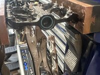
I put some vice grips on the axle nut to keep it from spinning.
IMG_9814.jpeg
I clamped the pedal in my vise and then used a punch to make a start for the drill.
IMG_9816.jpeg
I then followed that with a spot drill. These are more rigid than a standard drill, so great for starting holes in tough material. Ideally I'd do this on the mill, but no good way to clamp it given I need to hold that axle nut still.
IMG_9811.jpeg
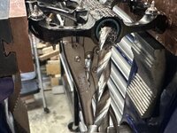
On these scenarios, my next step is typically a LEFT hand drill, as lots of times as its drilling, it will grab it and pull it out for you. Problem here is Titanium is incredibly difficult to drill. There is a reason they use it as coatings on drill bits.
 
OP
G

Grant Gunderson

Well-known member
Joined
May 17, 2013
Messages
2,330
Location
Bellingham, WA
IMG_9817.jpeg
So out comes my solid Carbide drills. These are stupid expensive, and it's generally a bad idea to use them in a hand drill. However they will drill what no other drill bit will touch. So I have slowly been acquiring them in the most commonly used sizes as I need them. The carbide drilled the Titanium like butter.
IMG_9819.jpeg
I then tapped a Rensteiger extractor into the hole. These things are the best things ever for removing broken bolts. The have hardened edges that help to dig into the broken bolt.
IMG_9820.jpeg
I could then easily remove the nut and pull the bearing out.
IMG_9822.jpeg
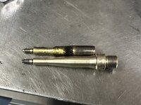
I then used a pin punch to drive the broken axle out.
IMG_9824.jpeg
IMG_9831.jpeg
So the replacement axle I have is for a different generation of pedal, so it requires a bushing with a slightly different profile.
IMG_9827.jpeg
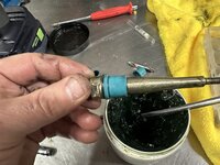
This is a pedal bushing removal tool. You drive it into the pedal shaft side first, you then tap the shaft to drive it back out the opposite directions forcing the bushing out.
IMG_9829.jpeg
New axle, new bushing and a bunch of waterproof grease and it all goes back together and I can still use my favorite pedals!
 
OP
G

Grant Gunderson

Well-known member
Joined
May 17, 2013
Messages
2,330
Location
Bellingham, WA
It's now time to shaft gears bit into skiing. Ski season here is just around the corner. So I need to get the lady friends skis setup.
IMG_9844.jpeg
After working in the ski industry for 25 years, I have developed a collection of binding jigs that surpasses most ski shops. I dont think there is a binding in existence that I dont have a jog or combination of jigs that will mount it. After all my ski bench is what pays the bills doing catalog shooting season.
IMG_9845.jpeg
So the first step is to grab the jig for the binding being mounted, it then gets sized to the ski boot.
IMG_9846.jpeg
The jig then gets lined up with the boot center make on the ski. Older skis, especially K2 used a Toe line mounting method. Where you would line the boot toe up with the mark on the skis. Since all bindings (other than kids and rentals) only adjust for length in the heel, the Toe line system was better, but the entire industry moved to the boot center method.
IMG_9856.jpeg
Instead of using standard Alpine binding screws. I like to mount skis using inserts, these used to be made by Binding Freedom and Quiver Killer, I now just source them from Sun Valley Ski Tools.
IMG_9842.jpeg
Using the binding jig, I drill the skis first with a standard ski drill bit, then a special stepped drill bit for the inserts and then finally use a bottoming tap to tap the hole for the inserts. Teh jig keeps everything aligned and square. I then counter sink the holes with a special counter sink bit. The inserts then get screwed in with a coating of Fast Cap 2CP industrial CA glue.
IMG_9851.jpeg
The binding screws then get a coating of Vibra-tite. This works way better than standard locktite and it wont react with the ski binding plastics either. Note these screws are M5 screws, but have a special head profile that is anti-rotation just like a standard Alpine binding screw, and they use a #3 posidriver for installation. Normal M5 machine screws have a slightly different head profile and will actually pull though the ski binding mounting plates.
IMG_9847.jpeg
BTW there is a **** ton of different binding screw lengths and head types!
IMG_9848.jpeg
Here you can see just a few of them!
IMG_9852.jpeg
For mounting the bindings, regardless if I'm using the inserts with the machine screw threads or alpine binding screws with wood threads, I start with using the torque limiting setting on my Festool CXS driver.
IMG_9853.jpeg
The torque spec for ski binding screws regardless of the type is 4NM so I used torque limiting screw driver to set the final torque on each.
 
OP
G

Grant Gunderson

Well-known member
Joined
May 17, 2013
Messages
2,330
Location
Bellingham, WA
IMG_9857.jpeg
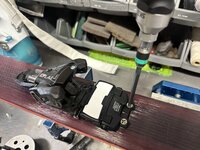
On the shift bindings, you have to screw the back screws down first, then slide the toe piece back and tighten down the two infront of the AFD.
IMG_9860.jpeg
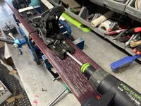
Ski bindings uses to always slide onto the track from the rear, now almost all of them slide on from the front, so the Festool driver in reverse makes quick work of getting it on the track.
IMG_9862.jpeg
I then place the boot into the binding, and then crank the forward pressure until the metal tab is in the plastic notch on the back of the heel piece. This is critical.
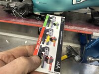
IMG_9863.jpeg
A simple card is the go no-go gauge for setting the AFD height for the boot toe. This is also critical.
IMG_9864.jpeg
The card needs to slide in and out snugly but not flex when doing it. My lady friend has Alpine boots, so the AFD is a lot higher then her new touring boots will be once they arrive, however since she is going to stay in the same size of shell, there will only be a few mm difference in the forward pressure setting to adjust as with the AFD.
IMG_9865.jpeg
The DIN on the bindings then needs to be set. This is the standard DIN chart it's the same for all bindings. You first find the skier's weight on the left, then go across to the right and find the boot sole length. This is the setting for a beginner skier. You then move down one spot vertically for an intermediate skier, or two for an advance skier. However I find these settings a bit conservative. According to the chart I'm a 8.5 DIN. I currently set mine to 10 and thats appropriate for me. Back I the day when I was 25 years younger and had fresh knees I would often ski with a din of 16~18! Ski bindings have come a long way are have more elastic release patterns now, so I'm able to ski at a much lower DIN. It's not uncommon for a WC racer to ski a very high din. Most World CUP level race bindings have a DIN range of 8~16, and I have even owned race bindings in a past with a DIN of 18~24! I gave those high din ones to a sit skier.
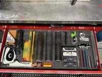
IMG_9866.jpeg
Any time I get new skis, I like to take them to a shop that has a Wintersteiger Jupiter machine. Those machines are fully automated and do things, you simply cant do manually, such as grind in a base pattern. Ski bases are not flat plastic, they have small micro groves that help channel the moisture when you are skiing, and there is countless different patterns. Above is my hand tools for basic ski maintenance.
01_2202074980.jpg
This is a shot of a race ski straight off f the Jupiter machine at GMVS, held by Scott Kennison. If you are an aspiring WC level reader GMVS is where you start your career. These base profiles can vary from straight lines to a more complex pattern as shown here, and they are closely guarded secrets, as the base profiles have more effect on ski glide and speed than wax does. Basically tho, you want a more complex pattern for warmer / wetter snow and a more linear pattern for colder / drier snow. In addition to having the bases ground, I like to have the edges of the skis ground to a specific bevel. Typically I like a 1 degree base bevel and a 3 degree side bevel. This a bit much for most people, so standard tends to be a 0.5 degree base bevel and a 1 degree side.
 
OP
G

Grant Gunderson

Well-known member
Joined
May 17, 2013
Messages
2,330
Location
Bellingham, WA
IMG_9866.jpeg
So in order to maintain these ground profiles, I mostly just use the edge profiles tools on the right of this drawer with diamond files. I rarely use the standard metal files unless I'm fixing edge damage.
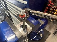
IMG_9874.jpeg
For hot waxing, I upgraded to and industrial level wax iron from Witnersteiger. This heats up way faster and holds temp way better than any of the consumer grade Irons. I also. cut its cord to work with my over head reel to keep it out of the fresh wax.
IMG_9877.jpeg
I drip my preferred wax combo for the temp on with the iron.
IMG_9878.jpeg
The smooth it out.
IMG_9884.jpeg
I then use a plexiglass scraper to remove the excess. I hate dull scrapers so I only use one edge per ski. After a pair of skis, it goes into the pile to get sharpened with my scraper sharpener.
IMG_9885.jpeg
I then use a roto-brush to remove the rest of the excess wax. We just want the wax to fill the p-tex poors, and not the base structure. Too much wax is actually slower and will pull out from the base sooner so more wax lasts a shorter time.
IMG_9887.jpeg
here you can see the base structure after brushing.
 

quadrcr87

Well-known member
Joined
Jul 5, 2013
Messages
1,036
Location
Travelers Rest, SC
You are a wizard Grant! I look forward to your updates because I always learn something. I wax and maintain my own snowboard, but I think they are a lot less complex than skis. Lucky for me all the binding holes are predrilled with inserts when I get a new board. Nut much snow now that I moved to SC but I can MTB year-round!
 

Xti04

Well-known member
Joined
Nov 11, 2016
Messages
2,342
Awesome to see how you setup the skis! So for the last 2 years I have been to our local ski shop to try and buy a complete ski setup as I have finally gotten to a point where I no longer want to rent and wanted to support my local shop. The owner will NOT take my money. I have been trying to buy a set of twin tips, boots and bindings and he will not sell me anything. Always tells me to wait till September, or that he doesnt have what I need right now or some other excuse. I walk in with a stack of cash and he just wont take it. Burns me up and has kept me from buying anything at all. I never realized there was so much more to setup and I appreciate you sharing it!
 
OP
G

Grant Gunderson

Well-known member
Joined
May 17, 2013
Messages
2,330
Location
Bellingham, WA
Awesome to see how you setup the skis! So for the last 2 years I have been to our local ski shop to try and buy a complete ski setup as I have finally gotten to a point where I no longer want to rent and wanted to support my local shop. The owner will NOT take my money. I have been trying to buy a set of twin tips, boots and bindings and he will not sell me anything. Always tells me to wait till September, or that he doesnt have what I need right now or some other excuse. I walk in with a stack of cash and he just wont take it. Burns me up and has kept me from buying anything at all. I never realized there was so much more to setup and I appreciate you sharing it!
Thanks. The entire outdoor industry seems to be in financial turmoil right now. I predict gear prices are going to drop! That being said, there is so many good skis and bindings out there these days, its tough to not get a good setup. That being said, I dont miss having to walk into a ski shop to get anything done. It was always an exercise in frustration dealing with some know it all staff that quite frankly never had a clue.

You are a wizard Grant! I look forward to your updates because I always learn something. I wax and maintain my own snowboard, but I think they are a lot less complex than skis. Lucky for me all the binding holes are predrilled with inserts when I get a new board. Nut much snow now that I moved to SC but I can MTB year-round!
Thanks! While mounting skis is way more complex than putting binders on a snowboard, the same principles for wax and base prep are applicable to both. The nice thing about being in Bellingham, as long as you dont mind some mud, the biking is pretty good year round, but every November I'm ready to switch focus back to snow once it arrives.
 
OP
G

Grant Gunderson

Well-known member
Joined
May 17, 2013
Messages
2,330
Location
Bellingham, WA
Ski season is just around the corner here... in fact we got a ton of snow the last few days so I went for a tour yesterday with a friend, but bailed after 1 lap as anything steep enough to be worth skiing was too dangerous with the avalanche conditions... todays rain will fix that. So a good day for some shop time.
IMG_0619.jpeg
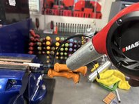
A friend dropped of a stack of kids poles for my son and his friend Evelina. Only issue is they are way too long, so I need to shorten them. Usually I can just remove the grips with a slide hammer, but these have been glued on. A few minutes with the heat gun softens the glue.
IMG_0623.jpeg
I have a ski pole specific slide hammer from SVST that is designed specially for removing grips without damaging the paint. If you dont have one of these the open end of a large wrench also works.
IMG_0624.jpeg
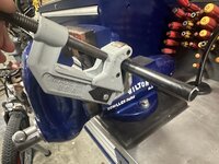
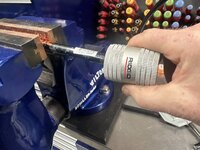
I cut the poles to length with a pipe cutter
IMG_0626.jpeg
Then used my rigid debuting tool to clean up the edges internal / external.
IMG_0627.jpeg
The grips then tap back on with a soft dead blow. No need for glue.
IMG_0628.jpeg
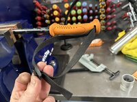
Finally pole strap loops should always have a half twist to them.
IMG_0634.jpeg
I then helped my buddy with his new G3 split board skins. The plastic backing that protects the glue during shipping was ***** to get off!
IMG_0639.jpeg
The skins are wider than the board so they need to get trimmed. Ideally you want just the edge showing. I used to do this with a utility knife, but they make these handy trimming tools now that make it way simpler!
IMG_0640.jpeg
Just pull it along the edge and it automatically cuts the off set. K2 and G3 include these with the skins, other brands dont, so I keep them around for use with other brands.
IMG_0642.jpeg
Next he asked if I could fix the edge of his kids old rock board. Just needs to last for a few days until we have an adequate base. First step is marking where the notces in the edge are.
 
OP
G

Grant Gunderson

Well-known member
Joined
May 17, 2013
Messages
2,330
Location
Bellingham, WA
IMG_0644.jpeg
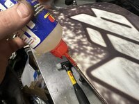
I apply some CA glue to it. Epoxy would be better, but this is just a short term fix.
IMG_0643.jpeg
I then tap the edge back in.
IMG_0646.jpeg
Next I drill the countersink a series of holes off set from the notches in the edge.
IMG_0647.jpeg
I then drive in some screws to hold it, and spread the squeezed out glue around and then hit it with some activator. Once cured it all gets filed down smooth.
IMG_0702.jpeg
On another note, When we got back from ski touring. I find my ******* neighbor cut my tree down, that was clearly on my side of the property line. Not happy!
 
To avoid these ads, REGISTER NOW!
Top Bottom