To avoid these ads, REGISTER NOW!

Above 1200 Sq/FT The Action Sports Garage

Wokspaces above 1200 squarefeet.
OP
G

Grant Gunderson

Well-known member
Joined
May 17, 2013
Messages
2,331
Location
Bellingham, WA
IMG_3576.jpeg
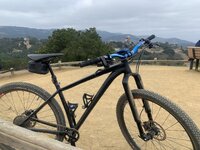
I took Stian out to ride the brand new Y-road trail system here. He loves hedgehogs, so was pretty excited to see they named that climbing trail that! No riding pics of him this time and we ended up riding the trial fast hitting a ton of jumps. The DNR partnered with the local WMBS trail group to build a machine built 2500 vertical foot climbing trial as well as a bike park style blue flow trail down. I normally hate flow trials, but this is really damn fun, and the entire area once its built out will dwarf the. Galbraith trail system. I'd love to find some property out this way some day. Post ride he told me that was his top 3 rides / favorite trails of all time. Btw, I picked up these Rock Bros kids riding glasses on amazon for $30 and they are great for him! I'm used to getting smith / Scott / Oakleys for free from work, but that supply is dried up and these glasses are just as nice, so ended up ordering my self a set.

Despite the amazing spring weather we have been having, I'm way behind on my spring to do list. The yard work I typically do in the fall didn't happen this year due to the divorce trial taking up all of my time, so I'm playing catch up with that, and then finally got around to taking the studs off of the truck and pulling the bed weights out for the summer. So that only left a little bit of time to work on the vise. I have both a Reed 2C and a Starrett Vise I picked up last year that also need a restoration on, so I'm going to do all 3 at once to scale my time and materials costs.

IMG_3594.jpeg
I got the entire lot of them wire wheeled today, so other than machining the Starrett and the Reed, they will be ready for the Epoxy Primer.
IMG_3591.jpeg
On all 3 I found some remanets of someone sparking a welder on the slides. See here just right of the oil port on the Reed. I dont want to take material off of the slides, so they stay tight as possible, as there isn't a lot of good options to shim the slides.
IMG_3592.jpeg
So I hit all of the slides with both a coarse an then fine stone, using the same figure 8 technique I use on the mill table to keep it burr free. This only removes minimal material and smoothes everything out.
IMG_3593.jpeg
My recycling bin makes a great outdoor work bench. Whenever I build out my next shop space. I really want to setup a covered shed area for the buffers / grinders and doing dirty things such as wire wheels / sanding, etc. It keeps the rest of the shop way cleaner.
IMG_3596.jpeg
It interesting just how massive the Reed 2C is in the middle. For a 4" vise its built as heavy as the 5" offset on the right, It makes the Starrett look tiny, and its a substantial vise in its own right. I doubt I'll end up keeping all 3, but am torn between the Starrett and the Reed, so we will see what once I choose to let go of when this is all done, but I'm leading to keeping the Reed and obviously the Dawn.
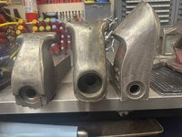
IMG_3597.jpeg
Hopefully I can get some machining done tomorrow, but given how nice the weather is, I dont know if that will happen between riding bikes and getting ready for a trip out to the San Juan Islands this weekend with the kids and the lady friend for her Bday. At least we will be bringing the bikes along too.
 
To avoid these ads, REGISTER NOW!
OP
G

Grant Gunderson

Well-known member
Joined
May 17, 2013
Messages
2,331
Location
Bellingham, WA
Been busy with suspension work but hopefully back to the vises soon.

IMG_3799.jpeg
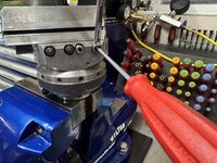
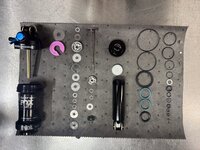
These Fox DPS shocks appear simple, but require an incredibly precise calibration when servicing requiring the use of a dial indicator. However that’s no big deal when you are used to doing precision machine work and have an entire drawer full of dial and test indicators.
IMG_3805.jpeg
 
OP
G

Grant Gunderson

Well-known member
Joined
May 17, 2013
Messages
2,331
Location
Bellingham, WA
IMG_4016.jpeg
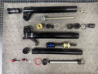
Been crazy busy with suspension work. This is the air cartridge out of a fox38 torn down.
IMG_4017.jpeg
and a monarch plus

IMG_4019.jpeg
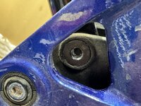
A guy came in with an e-bike with the lower shock bolt being completely stripped.
IMG_4021.jpeg
Pounded in a Proto RBRT hex tool. These things can work miracles for stripped hex bolts but no luck here.
IMG_4023.jpeg
So I put the link and the shock into the vise of the Bridgeport and used the cone side of the edge finder to find the center of the bolt.
IMG_4024.jpeg
Do the X axis then Y and then repeat 3 times is pretty damn accurate.
IMG_4026.jpeg
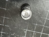
Started the hole with a center drill for accuracy then worked up to a bit just shy of the thread rood diameter. Since I was drilling from the backside the normal RH drill eventually spun the bolt loose.

IMG_4027.jpeg
All that was left of the bolt center was the threads themselves turning the end of the bolt into a spring.

Can’t be any more precise than that!
 
OP
G

Grant Gunderson

Well-known member
Joined
May 17, 2013
Messages
2,331
Location
Bellingham, WA
IMG_4041.jpegIMG_4039.jpegIMG_4036.jpeg
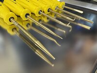
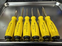
I only use brass tooling when working on mountian bike suspension, so it’s impossible to scratch the sealing surfaces ( I see way to many shocks that people have butchered by scratching them with steel picks). Problem is that with my dupuytren’s the small diameter of the picks hurts my hands so I made up a set of custom tools to do the job.
 

Johanfpa

Well-known member
Joined
Dec 27, 2016
Messages
241
Location
Aberdeen Scotland
Do you have maintenance manuals you can consult before taking these sometimes very intricate suspensions apart or once you know how to dismantle one the techniques used are more or less alike? I'm just asking because I would be afraid damaging them beyond repair while trying to take them apart.

Love your setup/tooling and all the projects you have done to a very high standard.

Also glad to see you were able to convert one of your hobbies into a paying business when your photography work dried up!
 
OP
G

Grant Gunderson

Well-known member
Joined
May 17, 2013
Messages
2,331
Location
Bellingham, WA
Do you have maintenance manuals you can consult before taking these sometimes very intricate suspensions apart or once you know how to dismantle one the techniques used are more or less alike? I'm just asking because I would be afraid damaging them beyond repair while trying to take them apart.

Love your setup/tooling and all the projects you have done to a very high standard.

Also glad to see you were able to convert one of your hobbies into a paying business when your photography work dried up!
Thanks. Fox and Rockshoxs have great technical support for their products, but once you’ve done enough of them it’s really just knowing the proper torque range for the shim stacks and sealing surfaces, along with oil weight, IFP height and IFP pressure. Some brands provide zero tech info but those are pretty easy to figure out as well. It really comes down to having the correct specialty tooling.
 

F-22

Well-known member
Joined
Jan 23, 2022
Messages
1,830
Elan makes great skis but they haven’t been very successful in pushing into the NA market mostly due to a lack of marketing. Their bindings are rebranded tyrolia.
Was just recently reading up a bit about Elan. Quite interesting. I knew they were early with the carving/parabolic skis, but it seems they were the first to actually start up production of skis with a strong sidecut in 1991 and it revolutionized skiing.
Too bad they didn't properly cash-in on it. I heard they're close to bankruptcy or partially already got bankrupt a couple years ago.

I haven't skied for 20 years but I would really like to try again (over here in Slovenia, the Alps are close...). I know very little about the subject and there is so many models and brands. Which skis and brand would be your recommendation for a beginner on regular European/Alpine skiing resorts? Most popular brands here besides Elan are probably Head, Völkl, Rossignol...
 
OP
G

Grant Gunderson

Well-known member
Joined
May 17, 2013
Messages
2,331
Location
Bellingham, WA
Was just recently reading up a bit about Elan. Quite interesting. I knew they were early with the carving/parabolic skis, but it seems they were the first to actually start up production of skis with a strong sidecut in 1991 and it revolutionized skiing.
Too bad they didn't properly cash-in on it. I heard they're close to bankruptcy or partially already got bankrupt a couple years ago.

I haven't skied for 20 years but I would really like to try again (over here in Slovenia, the Alps are close...). I know very little about the subject and there is so many models and brands. Which skis and brand would be your recommendation for a beginner on regular European/Alpine skiing resorts? Most popular brands here besides Elan are probably Head, Völkl, Rossignol...
Elan at one point had the largest ski factory in the world and they actually produce skis for a ton of other brands. So I think some of this issue is they’ve done more OEM manufacturing than marketing their own.

It’s actually tough to find a bad pair of skis these days. All of the major companies produce really good stuff. Volkl has always made some of the best stuff, and the newer stuff from Head is really good too.
 
OP
G

Grant Gunderson

Well-known member
Joined
May 17, 2013
Messages
2,331
Location
Bellingham, WA
Life's been busy as heck as usual, but in a good way. Just got back from a quick trip to Sedona with the lady friend.
IMG_4133.jpeg
A while back she purchased .6 acres in Sedona, and after working on the design for the last year, we flew down for a quick trip this weekend to meet with our builder and start picking some of the furnishings. We are on a budget (especially by Sedona standards) but the view from the house is going to be amazing, not to mention the ride access. To be clear this is her project, and I'm along for the ride / putting in sweet equity.🤣
IMG_4167.jpeg
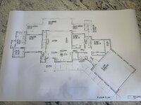
House will be roughly 2100sqf on the main level, than about another 1000 or so on the lower once it's done. Plan is to build the main level, and leave the lower level unfinished for now. Then once we are in the house and finances recover, I'll do the lower lever build out. The lower will have at least one if not two guests suits, and then either a large flex room or (most likely a work shop space). We don't ever plan on this being a main residence, and its just going to be a vacation house for us to escape rain season on the PNW and ride bikes.
IMG_4183.jpeg
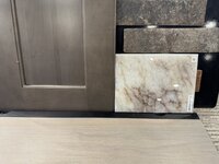
Lots of decisions to be made, but she's already picked out finishes for the cabinets, counter tops and the main flooring. We will do a Franke granite sink as well. The plumbing fixture decision process is pretty overwhelming... so we need to spend some time on that selection here before we head down next time. This is going to be a big project, but we both feel pretty confident in the builder she selected, so excited to see this starting to move forward.
IMG_4155.jpeg
Sedona is a pretty crazy spot in terms of geography / landscape, the mountain biking and also the architecture. We are building a very modest house, by the standards of one of the near by neighbors. I think that place is something like 21K sqf!
IMG_4126.jpeg
We got out for a pretty solid ride while in town too and did 20 miles and 3500 feet of vert on the analog bikes in the 85 degree heat. Riding in Sedona is like polar opposites to here in Bellingham, not a lot of vertical, but way more tech riding and obviously lots more rock. Will be great for escaping our mud season up here!

IMG_4200.jpeg
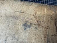
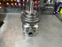
I've been looking to pick up a boring head for the mill for a while. Have been looking ever since I bought the mill for a quality one, as I'm not a fan of Chinese tooling. I have project that I urgently need a boring head for and was about to head down the street to pick one up at Grizzly, when I saw a guy on a Facebook group Im following post a Wolhauper 4s5 for sale. If you're not familiar, these are the Cadillac of boring heads and are stupid expensive! Typically they are on Ebay for $1500+ and are really hard to find in non cat40 tooling. This guy had one with a ¾ straight shank, so it will work in both the Bridgeport and the Monarch 10EE. Best part is he only was asking $300 and supposedly had just rebuilt it.... So I jumped at it, gave him a call, and felt confident he was a straight shooter on the phone, so sent him some funds via paypal, ended up being just over $400 after shipping. these are stupid heavy, and come in a wooden box, Made in Germany too, as per the stamp on the box!
IMG_4201.jpeg
guy did a great job packing it too.
IMG_4202.jpeg
USPS being what it is, got it to me in 3 days, but they **** kicked the box. Note all of the broken wood.
IMG_4205.jpeg
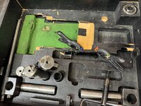
Some small CA glue and some spring clamps and I got it mostly back together. I normally hate tooling being in wooden boxes / blow molded cases, but this box is pretty efficent in its setup, so I might keep it in it, in my Lista cabinets.
IMG_4206.jpeg
Only thing it apears to be missing is some of the hardened ground shims for using smaller diameter boring bars in it.
 
Last edited:
OP
G

Grant Gunderson

Well-known member
Joined
May 17, 2013
Messages
2,331
Location
Bellingham, WA
IMG_4209.jpeg
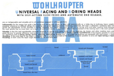
Whats so special about these boring heads is that they can auto feed out in diameter. Screenshot 2025-05-28 at 9.05.05 PM.png
So in addition to standard boring / facing / fly cutting, you can use it to cut internal groves (O-rings) undercuts, and even tapered bores.
Screenshot 2025-05-28 at 9.03.21 PM.png
So they are damn useful, and being German made they are super high quality and very precise.

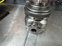
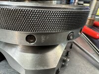
Only problem is when I got it the damn autofeed didnt work! WTF? thats the entire reason why I bought it. These have 12 pins around the side and when you push a different # of the pins in, you get it to auto feed out at a faster rate. Pin #9 wouldn't push in at all. Something clearly isn't right. Made a quick call to the seller to let him know it wasn't working and to confirm I wasn't missing something obvious. We then agreed it made sense for me to take it apart and see what's up.
IMG_4210.jpeg
These two screws hold the main feed screw in place.
IMG_4211.jpeg
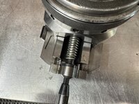
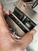
With those out, I could manually feed the screw to separate the boring bar holder from the head. It uses dove tailed ways just like a lathe or mill.
IMG_4214.jpeg
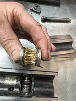
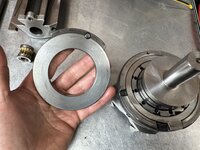
I could then pull the bronze worm wheel out, it's in great shape, as is the worm shaft on the fine adjusting spindle. Note, the rings on the side of the worm gear have two tabs that have to properly engage with the casting when going back in.
IMG_4216.jpeg
Everything about these heads screams quality, even in how the engrave the SN on the inside as well, The boring bar holder is hand fitted to the main head, so the SN's should match.
IMG_4217.jpeg
Rotating the shaft, all of the gearing apears to be intact, so thats a relief. The issue must be in the push pin feeding system.
IMG_4219.jpeg
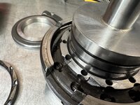
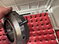
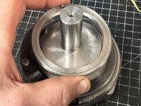
The upper portion of the head is held together by a very large retaining ring. These Wiha snap ring pliers are the cat's meow, as they have notched tips that better grip retaining rings and help prevent them from flying across the shop as well.
IMG_4222.jpeg
Once the snap ring is off, this bushing comes off next. Not the pin it, it needs to be orientated between the legs of the snap ring.
 
Last edited:
OP
G

Grant Gunderson

Well-known member
Joined
May 17, 2013
Messages
2,331
Location
Bellingham, WA
IMG_4221.jpeg
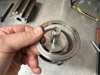
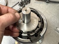
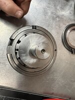
I can then lift the clutch assembly off. When in use you insert a stop bar into the clutch ring bore. If this is held stationary the head auto-feeds if it's allowed to spin, it operates like a standard boring head. If it encounters too much resistance, the spring loaded clutch lets go, to protect the head. Simple and smart.
IMG_4224.jpeg
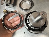
This is the bottom of the clutches retaining ring, and you can see the notch in the control ring the clutch pin fits into, the larger notch is a gap that allows you to swing the tabbed release ring to release the auto-feed pins.
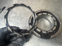
IMG_4225.jpeg
IMG_4226.jpeg
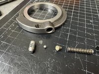
Thats when I had a part fall out. Well I'm willing to bet thats the issue!
IMG_4228.jpeg
I bet thats from pin #9 that wasn't working!
IMG_4231.jpeg
The release ring just lifts off. Look at that machining. Note the spring in the spring. It interacts with a curbed piece to reset the pins.
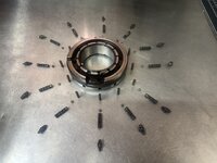
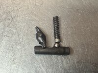
In each of the vertical bores there is a lever that forces the feed pins to release. In order to remove anything else, you need all of the feed pins to be reset to the full out position.
IMG_4233.jpeg
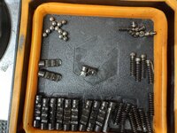
The smaller vertical bores have a spring, a bushing fitted into the spring and then a ball bearing under them. They are all held in place by a large wire ring that circumnavigates all off the pin spring assemblies.


IMG_4242.jpeg
IMG_4243.jpeg
I could then fish all of the pins out using a magnet.
IMG_4235.jpeg
 
Last edited:
OP
G

Grant Gunderson

Well-known member
Joined
May 17, 2013
Messages
2,331
Location
Bellingham, WA
IMG_4236.jpeg
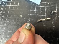
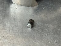
What will turn out to be one of two broken pins.
IMG_4244.jpeg
Lots of small parts, but it's fairly simple.
IMG_4247.jpeg
When the pins are pushed in, they engage with this star gear that then feeds the head. IE the more pins are pushed in, the more that rotate the star gear, thus giving you a faster feed. Thankfully it had little damage, just some shrapnel from a broken pin.
IMG_4248.jpeg
I reached out to the guy I bought it from. Told him, I thought it would be fair if he either refunds me the cost of the replacement pins, or my time to make them if I cant find replacement. They are not a standard dowl pin size. I dont use my pin gauge sets very often, but it's perfect for this. The pins work out to be .217" so that works out to be 5.5mm in Diameter. If I cant find replacement pins, I can use plastic injection molding pins as raw stock as they just so happen to be 5.5MM
IMG_4251.jpeg
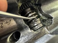
The worm shaft is retained by a small flat head dog point set screw. Whats unique about this, is they used a small wire retaining ring through the flat head screw to keep it from ever working loose. Clever! ITs amazing what you learn taking things apart.

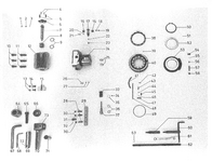
I did some searching and it turns out that AHB Tooling & Machinery is a distributor for Wohlhaupter. Called them up, spoke to a sells guy there and in 15 minutes he sent me a parts diagram!
Screenshot 2025-05-28 at 9.41.30 PM.png
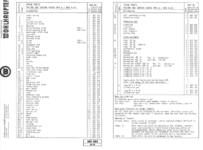
And the parts list!
Screenshot 2025-05-28 at 9.41.57 PM.png
When customer service seems to be lacking everywhere nowadays, it's really nice to find service such as this. So fingers crossed they have the parts I need in stock.
 
Last edited:
OP
G

Grant Gunderson

Well-known member
Joined
May 17, 2013
Messages
2,331
Location
Bellingham, WA
Parts are ordered for the Walhaupter so waiting on them to put it back together.

Took the E-bike out for a spin and had an ungodly sound coming from the Shimano EP8 motor. Ended up with an E010 error code 3 times on the climb. Each time I could feel the motor slip before the power cut out. With 4000 miles on the motor over the last 3.5 years I’m well outside of the warranty period and Shimano states the motors are not repairable.
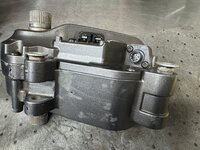
IMG_4326.jpeg
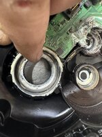
Dropping it from the frame first thing i noticed is that two of the presses in bushings that take the mounting bolts have pulled out. That should be an easy fix to press back in with some retaining compound.
IMG_4329.jpeg
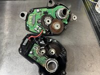
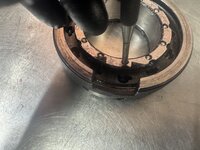
The motor is composed of two halves. They are held together buy 6 button head screws with a T25 head. I had two of the heads strip when separating them. Should have used some heat on them as they were installed with red locktight. Turns out they are 6mm bolts but instead of the standard 1.0 pitch they are .75. Wtf? Shimano couldn’t use standard bolts? Guess that’s their anti-tamper solution. Ordered replacements from McMaster at $6 a bolt. There is also a thin bead of gasket sealant holding the two halves together. That’s easy to separate with a razor blade.
IMG_4330.jpeg
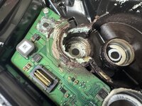
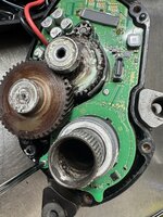
On the electronic connection side you can see some very dirty grease and grime has made it onto the board. Note the connector that links this board to the other side. Previous generation used a ribbon cable. I really hope that’s not a discoloration on the board indicating it’s fried. Guess we will find out when I clean it up. However at this point I got nothing to loose trying to fix it.
IMG_4331.jpeg
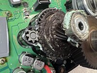
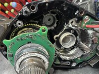
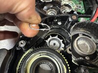
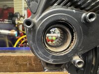
Here is the drive side. You can see the small pinon gear coming from the actual motor drive unit. It drives this larger gear in the drive train. Look how much dirt and **** has made its way into there.
IMG_4332.jpeg
The main drive axle has this thin bushing / spacer on it. I’ve seen these motors have a lot of axial play so I’m guessing those don’t have the proper thickness shim.
IMG_4333.jpeg
It belongs in this side of the casing.
IMG_4334.jpeg
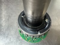
I believe this board that surrounds the drive axle is the torque sensor. Given the electronics on the drive axle I’m betting it’s some sort of fancy Hall-effect sensor. It’s held in by two small screws. Those are JIS as indicated by the dot on the heads.
IMG_4335.jpeg
With that board loose I can then remove the gear train. Those bearings are shot.
IMG_4338.jpeg
And that’s a lot of crud / **** in there.
IMG_4337.jpeg
I can now pull the main drive axle out along with the sensor board that surrounds it. Didn’t get a picture of it but those rectangular holes in the board align with arrows in the black plastic shaft collar bellow them.
 
OP
G

Grant Gunderson

Well-known member
Joined
May 17, 2013
Messages
2,331
Location
Bellingham, WA
IMG_4340.jpeg
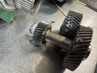
That’s the majority of drive train removed from the motor housing.
IMG_4341.jpeg
Note the large gear with the needle bearing is still in the motor clam shell. It will need to get pressed out.
IMG_4342.jpeg
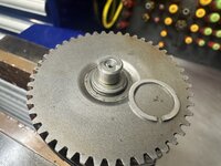
This wave spring provides an axial preload to the primary gear shaft.
IMG_4343.jpeg
It lives here.
IMG_4347.jpeg
I can lift the sensor board off of the main axle now. It has a small connector that presses into the main board. Thankfully no ribbon connector to worry about.
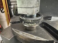
IMG_4349.jpeg
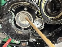
This is the large gear with the needle bearing after I pressed it loose from the housing.
IMG_4350.jpeg
Lots of crud in there!
IMG_4351.jpeg
Once out I used a drift in the arbor press to press the needle bearing out. It’s quite rough.
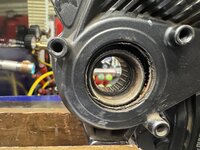
IMG_4352.jpeg
It’s got two identical shaft seals to seal it you can see here the seal clearly failed. Have not been able to find a replacement seal yet.
 

Attachments

  • IMG_4349.jpeg
    IMG_4349.jpeg
    687.6 KB · Views: 5
OP
G

Grant Gunderson

Well-known member
Joined
May 17, 2013
Messages
2,331
Location
Bellingham, WA
IMG_4344.jpeg
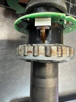
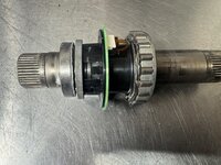
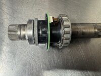
Here is the main axle. You can see the shaft side electronics here. I’m certain this spraug clutch is my main problem. Look at the rust on it.
IMG_4345.jpeg
No idea yet on how to remove it. It appears to have two tabs that interact with the shaft assembly and has a spring to engage. I need to study this assembly before I try to take it apart. I’ll come back to it.
IMG_4353.jpeg
In order to get the end bearing off if this shaft assembly I had to use a bearing separator in the arbor press. Note it’s oriented to load the frame off the separator and not its bolts.
IMG_4354.jpeg
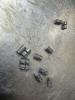
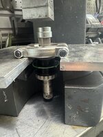
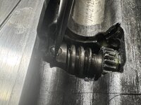
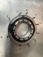
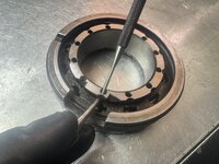
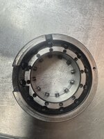
****! There was a snap ring under that bearing holding the larger gear on. It came off when I pressed the end bearing out and the internal spraug clutch inside that gear fell out. There are 16 cans and 4 rollers. So the spacing is 4 cams then a roller than repeat. These are held in place by a circumference spring.
IMG_4355.jpeg
Note all of the cams have a longer and a shorter side so all need to be oriented the correct way. It’s hard to see the difference they are so small.
IMG_4360.jpeg
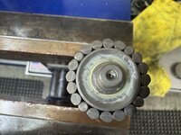
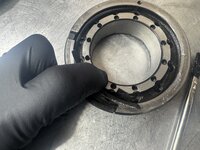
All back together. Hopefully it’s the correct orientation. If not I simply have to flip the entire spraug clutch over to change the direction.
IMG_4365.jpeg
Here you can see how the clutch interacts with the inside of the gear. I’m waiting on some special grease before I install it. IMG_4366.jpeg
The offending snap ring. I’ll probably replace with an E-clip.
 

Attachments

  • IMG_4367.jpeg
    IMG_4367.jpeg
    806.7 KB · Views: 2
  • IMG_4369.jpeg
    IMG_4369.jpeg
    638.5 KB · Views: 2
Last edited:
OP
G

Grant Gunderson

Well-known member
Joined
May 17, 2013
Messages
2,331
Location
Bellingham, WA
IMG_4367.jpeg
Now on to Pandora’s box, er shaft
IMG_4371.jpeg
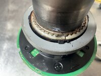
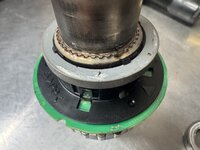
Here you can see the two tabs from that roller bearing. I don’t think it’s a clutch as the spring loaded tabs only allow it to rotate a few degrees. It’s got a large snap ring that holds it on.
IMG_4374.jpeg
I got the end bearing off using a bearing separator and a bushing to protect the end of the shaft

IMG_4375.jpeg

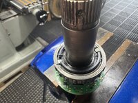
That sensor is epoxied on. And the epoxy is clearly cracked on this side
IMG_4378.jpeg

And the other, I may be fucked if its not fully attached to the shaft still.

IMG_4380.jpeg

I used those special Knipex snap ring pliers to remove the ring.
IMG_4383.jpeg
Snap ring is off
IMG_4385.jpeg
Here is one of the two tabs on that roller bearing and you can see both of the springs.


IMG_4387.jpeg
I don’t want to screw with those springs if I don’t have to.
 

Attachments

  • IMG_4383.jpeg
    IMG_4383.jpeg
    562.1 KB · Views: 7
Last edited:
To avoid these ads, REGISTER NOW!
OP
G

Grant Gunderson

Well-known member
Joined
May 17, 2013
Messages
2,331
Location
Bellingham, WA
If you succeed in repairing the unrepairable motor, that will be a nice added scope of work for your side business!
Possibly. I’ve done a lot of belt replacements on the older Brose motors for people. The issue with working in these motors is having access to the diagnostic software. I might invest in it, I’m too small to get a wholesale account from Shimano, so I have to go through one of the Distributors. For Shimano it’s QBP but they don’t have the best parts selection. BTI is the best distributor for them but they are the only one that denied me an account until I get a commercial space…. After chatting with the lady friend about this for a few months I’ve decided to move ahead with getting a shop space so currently trying to find one that won’t blow my budget. More on that as it unfolds. Full steam ahead.
 
OP
G

Grant Gunderson

Well-known member
Joined
May 17, 2013
Messages
2,331
Location
Bellingham, WA
Grant,
Is this the first one of these you've taken apart? Are you going off a manual, or are you just figuring out as you go? Either way, hats off to you! This looks like quite the undertaking!
This is the first Shimano I’ve taken apart. No manual that I know of for these as Shimano says they are not repairable.

So learning as I go.

IMG_4396.jpeg
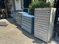
Been crazy busy with suspension work today, but these guys followed me home today. Won them at the Alcoa auction here for $150 a pop. They were filthy and need paint but I think they will clean up welll. They had a ton more but they were some other brand I wasn’t familiar with and would have bought a bunch more but I have zero place to store them until I can find a shop to rent.
 

zanyad

ALLIANCE MEMBER
Joined
Apr 26, 2018
Messages
2,842
Location
NE Ohio
Been crazy busy with suspension work today, but these guys followed me home today. Won them at the Alcoa auction here for $150 a pop.

I believe for $150 each that fully qualifies as a "you ****"

color me jealous as hell!

:+1: YOU ****
They had a ton more but they were some other brand I wasn’t familiar with
Stanley Vidmar, Lista, and Rousseau are the brands that I'm familiar with. All are quality.
 
OP
G

Grant Gunderson

Well-known member
Joined
May 17, 2013
Messages
2,331
Location
Bellingham, WA
:+1: YOU ****

Stanley Vidmar, Lista, and Rousseau are the brands that I'm familiar with. All are quality.
I now have 7 Lista’s and 4 Vimars and one Lyon, I’ve learned with Lista / Vidmar they use different sized dividers etc, so ideally it’s best to stick to one brand if possible. That being said it’s hard to walk past a good deal on any industrial grade parts cabinet.

The other cabinets were NU-Era. They looked to be extremely well made as well.

The bigger issue is I need more counter height cabinets and all of the NU-ERA were full height.

These Listas and especially the tall one I just picked up are going to need some work so maybe not quite a you **** deal. Spent some time yesterday starting to clean them out. I tossed a bunch of hydraulic hose and other **** but there were a few gems in them.
IMG_4427.jpeg
A bunch of Proto ¾” drive sockets. Don’t really have an immediate need for them, but they will be nice to have. Put them in some evaporust to clean them up

IMG_4428.jpeg

There was two Infersoll-Rand ¾ impact guns too. Gave one to my buddy for helping me move the cabinets. I much prefer my Milwaukee electric impact over air these days but for the rare time I’d use a ¾ this will serve me well
IMG_4430.jpeg
A few long blow guns too. Switched the fittings on them and the Impact gun to the Miltons I prefer and tested them out. These are going to be damn useful.
IMG_4429.jpeg
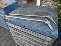
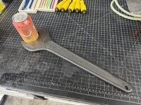
A 65mm facom wrench. No idea what the hell id use this on. So will probably sell it out maybe turn it into a door handle or something.

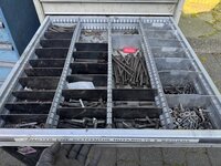
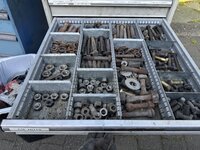
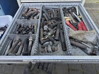
I haven’t touched the tall Lista yet. That’s in the docket after I get caught up with paying jobs today. It’s completely full of pipe and hydraulic fittings and a **** ton of hardware from ¼ to 1” plus.
 

Attachments

  • IMG_4428.jpeg
    IMG_4428.jpeg
    678 KB · Views: 0
OP
G

Grant Gunderson

Well-known member
Joined
May 17, 2013
Messages
2,331
Location
Bellingham, WA
The only other name that is similar is Equipto (that I know of).
I have head of those as well but haven’t seen them in person.

IMG_4451.jpeg
Had a guy bring in a Rockshocks RS1 today. Like everything on the bike works what’s old is new again with Fox releasing an upside down 38. Other than everything being upside down / backwards and left hand threaded it’s pretty much a standard rock shocks fork of that vintage just reversed.

The main issue with upside down forks is the amount of flex in them because the lower legs are free to spin in the uppers so you need a really rigid axle. In the case of this one the DT Swiss hub has a ton of wear on it.

Regardless it was a cool fork from the era but in my mind modern springs and dampers are light years better.

IMG_4477.jpeg
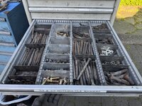
After I finished up with a bunch of customer bikes I started to tackle sorting out the large Lista it’s full of hardware.
IMG_4481.jpeg
Various pipe fittings

IMG_4482.jpeg
Zerks and grease footings and what I believe are hydraulic hose ends.
IMG_4483.jpeg
Misc. lots of drive train repair links, hose clamps.


IMG_4484.jpeg
⅜ and ½” hardwareIMG_4485.jpeg1/4 and 5/16
IMG_4489.jpeg
7/8
IMG_4490.jpeg
1”
IMG_4491.jpeg
Stainless and galvanized.

Since my existing Listas are mostly full of hardware already I’ll keep what I want out of this to finish off each of my drawers the sell the rest of the hardware asa bulk deal on FB. Thinking $150 would be pretty fair for it. That’s probably way less than a $1 a lb.
 

fishwatcher

Well-known member
Joined
Jan 26, 2023
Messages
759
I have head of those as well but haven’t seen them in person.

IMG_4451.jpeg
Had a guy bring in a Rockshocks RS1 today. Like everything on the bike works what’s old is new again with Fox releasing an upside down 38. Other than everything being upside down / backwards and left hand threaded it’s pretty much a standard rock shocks fork of that vintage just reversed.

The main issue with upside down forks is the amount of flex in them because the lower legs are free to spin in the uppers so you need a really rigid axle. In the case of this one the DT Swiss hub has a ton of wear on it.

Regardless it was a cool fork from the era but in my mind modern springs and dampers are light years better.
I have an RS-1 I’ve been considering sending to you for service as we’ve discussed. It’s cool that you’ve worked on one now.

I just need to find time to pack it up and ship it. This isn’t my primary bike, so it’s not been a huge priority.

IMG_1316.jpegIMG_1237.jpeg
 
OP
G

Grant Gunderson

Well-known member
Joined
May 17, 2013
Messages
2,331
Location
Bellingham, WA
I have an RS-1 I’ve been considering sending to you for service as we’ve discussed. It’s cool that you’ve worked on one now.

I just need to find time to pack it up and ship it. This isn’t my primary bike, so it’s not been a huge priority.

IMG_1316.jpegIMG_1237.jpeg
The one I just did turned out feeling great, but there is an issue with the guys Twin Xloc lockout button. Those SRAM hydraulic lock outs are nothing but a pain in the *** and a source of more problems then they are worth. They were / are the reason why so many of the non-electronic reverb posts are so damn in reliable. Personally I can’t think of a single good reason to use a fork lock out.
 

fishwatcher

Well-known member
Joined
Jan 26, 2023
Messages
759
The one I just did turned out feeling great, but there is an issue with the guys Twin Xloc lockout button. Those SRAM hydraulic lock outs are nothing but a pain in the *** and a source of more problems then they are worth. They were / are the reason why so many of the non-electronic reverb posts are so damn in reliable. Personally I can’t think of a single good reason to use a fork lock out.
Hmm. So just leave it unlocked. And
Remove the switch and cable? Mine seems to work fine. Not sure how I’d know if it went bad.
 
OP
G

Grant Gunderson

Well-known member
Joined
May 17, 2013
Messages
2,331
Location
Bellingham, WA
Hmm. So just leave it unlocked. And
Remove the switch and cable? Mine seems to work fine. Not sure how I’d know if it went bad.
He’s going to get a new switch for it. All the switch does is hydraulic operate the low speed compression adjuster to open / close the valve. They used to do a cable version of it too. You can test it by seeing if the fork noticeably gets stiffer when the button is out vs in.
 
OP
G

Grant Gunderson

Well-known member
Joined
May 17, 2013
Messages
2,331
Location
Bellingham, WA
IMG_4588.jpeg
Parts for the Wohlhaupter arrived today! Ao time to get it back together.
IMG_4590.jpeg
The fine feed screw feels like its bent, They wanted $200 plus for this part, so going to see if I can make do with it.
IMG_4592.jpeg
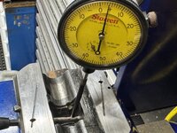
I set up the dial indicator on it with the part in the casting and rotated to find the low side.
IMG_4596.jpeg
We are only looking at it being .03mm out. I think I should be able to live with that! It's surprising how small of an amount the fingers can notice when rotating it. I marked the high side.
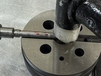
IMG_4597.jpeg
I supported the shaft on my Starrett bench block and gave it a few taps with the soft blow mallet to try and straighten it. Then re-rested it, its still out a bit.
IMG_4602.jpeg
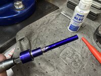
So I covered the shaft in Dyekem
IMG_4603.jpeg
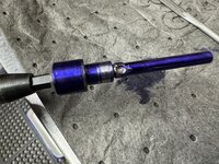
Inserted it back into the casting and rotated to find the high spots.
IMG_4604.jpeg
IMG_4608.jpeg
I then hit these with a 600X diamond file and repeated until I was getting even marks.
IMG_4609.jpeg
The manual recommend daily greasing with Molykote, the version I have seems too thick for the main shaft and ways, so I'll use a combination of spindle and Way oil for those parts.
 
OP
G

Grant Gunderson

Well-known member
Joined
May 17, 2013
Messages
2,331
Location
Bellingham, WA
IMG_4613.jpeg
Once I was happy with the shaft, I installed it along with its worm gear and its flat head set screw. Note the flat head needs to align with the groove.
IMG_4614.jpeg
So the retaining ring can lock it in place.
IMG_4638.jpeg
The feed control collar is next, it only has 36 small parts (that want to go flying) along with a retaining ring that holds the springs in.
IMG_4639.jpeg
This is the layout for each of the feed pins, with the cam that unlocks it, along with the ball detent, spring and pad.
IMG_4641.jpeg
All of the pins get inserted horizontally with the dove Tail end first, and the notches facing up.
IMG_4640.jpeg
here you can see they are all retracted.
IMG_4643.jpeg
I added some Molykote to each of the holes, then pushed the balls in with a pin punch.
IMG_4646.jpeg
Next I installed the wire retaining ring around it, the springs then need to get pushed down, so the retaining ring rests on top of them. Only took me an hour or so to figure out the best way to do this, and I had springs flying across the shop multiple times. It's amazing I didn't lose any parts. However, once I figured out the technique, it went really fast. Once I verified they were all correctly installed, I installed the cams.
IMG_4648.jpeg
And then manually tested pushing in and releasing each one. The cams need to be fully retracted before the next steps.
IMG_4649.jpeg
The dog point set screw that serves as the release spring stop gets installed next,
 
Last edited:
OP
G

Grant Gunderson

Well-known member
Joined
May 17, 2013
Messages
2,331
Location
Bellingham, WA
IMG_4650.jpeg
The long release spring goes in to the left of the pin.IMG_4651.jpeg
Followed by the return block
IMG_4652.jpeg
The machining on the return ring that actuates the cams is impressive.
IMG_4653.jpeg
I then used a screwdriver to hold the return block back, and then dropped the ring in. Note all of the cams / pins need to be retracted.
I then tested to make sure it all worked.IMG_4657.jpegI coated the main body and the feed control collar with spindle oil so it would be well lubricated and slid it on.
IMG_4659.jpeg
The stop ring goes on next, its got a dog with two detents in it, a ball, brass pad an spring. I cleaned all of the old grease out and related it with Molykote
IMG_4660.jpeg
little details like the cupped recess in the brass pad for the ball detent show the quality of these heads.
IMG_4661.jpeg
IMG_4663.jpeg
The stop ring then gets oiled and installed, and the dog is pushed down into the feed collar.
IMG_4664.jpeg
The top ring bushing also gets old and installed. The pin will sit between the ears of the large snap ring that holds it all together.
 
Last edited:
OP
G

Grant Gunderson

Well-known member
Joined
May 17, 2013
Messages
2,331
Location
Bellingham, WA
IMG_4665.jpeg
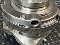
After the snap ring gets installed the top of the head is done.
IMG_4667.jpeg
With the head upside down in the ice soft jaws, I dropped in the bronze nut for the lead screw, its two side bushings have dogs on them that only fit into the head one way, I then inserted the Gib and slid the lower part of the head in, after I lubed everything with Way oil.
IMG_4669.jpeg
To adjust the gibs, yo use a #3 flat head, and once you have them set, you hold the screw with the screw driver, then tighten the lock nut with an 8mm wrench. It set it as tight as possible with out the Gib locking up the movement.
IMG_4671.jpeg
The lead screw has a ball decent to lock it into 1 of 3 positions to index it. This is a bit different than most detents as a ball goes into each of the three greased holes in the shaft.
IMG_4673.jpeg
A cup, cup side up gets installed into the face plate, followed by a spring, this cup is what gives the spring detention.
IMG_4678.jpeg
I installed the lead screw then bolted it down with its two screws.
IMG_4681.jpeg
The boring head is done, so I test ran it on the mill. The auto-feed is smooth as butter! I cant wait to use it, but too many priority projects first.
 

LXCam

ALLIANCE MEMBER
Joined
Apr 23, 2013
Messages
19,205
Location
AZ
Dang Grant, it’d been a while since I got into your thread. You’ve been busy :eek2:

If we do get a chance to get together on one of your trips down here make sure to remind to grab you some lista dividers, I’ve got a bunch of brand new ones that I have no use for.
 
To avoid these ads, REGISTER NOW!
Top Bottom