To avoid these ads, REGISTER NOW!

The Craigslist shop (40 x 60)

OP
4

48flatbed

Active member
Joined
Mar 8, 2007
Messages
44
Location
Hills of Arkansas
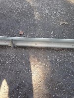
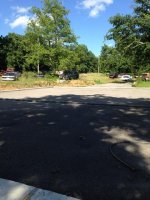
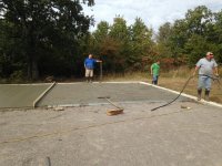
Once all the forms were pulled off I separated the reusable wood from the rest and burned the rest. Nothing like setting fire to 80 hard earned bucks! This was on Sep 8 of 2015, as I mentioned earlier this is a pay as I go project so I am sloooww. :( Next it was time to put in some fill. I used Crusher dust for fill. I brought in 3 separate loads, each a week apart, smoothed out and compacted each load. Each load was around 22 tons and cost about $270. I shot the laser on the final compaction to get it as flat as possible.

previous materials total $700 Concrete $ 1900
fill $815
new materials total $1515 Concrete $1900
new grand total $3415
 

Attachments

  • IMG_0988 (Copy).JPG
    IMG_0988 (Copy).JPG
    37.4 KB · Views: 68
  • IMG_2075[1] (Copy).JPG
    IMG_2075[1] (Copy).JPG
    45.8 KB · Views: 87
  • IMG_1118 (Copy).JPG
    IMG_1118 (Copy).JPG
    45.5 KB · Views: 75
  • IMG_1339 (Copy).JPG
    IMG_1339 (Copy).JPG
    37.6 KB · Views: 75
  • IMG_1341 (Copy).JPG
    IMG_1341 (Copy).JPG
    40.9 KB · Views: 90
  • IMG_1342 (Copy).JPG
    IMG_1342 (Copy).JPG
    46.4 KB · Views: 77
  • IMG_1343 (Copy).JPG
    IMG_1343 (Copy).JPG
    35.8 KB · Views: 81
To avoid these ads, REGISTER NOW!
OP
4

48flatbed

Active member
Joined
Mar 8, 2007
Messages
44
Location
Hills of Arkansas
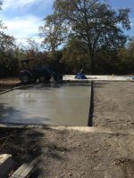
Heres a satellite view of the fill work. If you look closely just to the right of the upper right corner of the shop you can see another of my CL purchases. 8 I beams. :)
 

Attachments

  • homefill.jpg
    homefill.jpg
    84.1 KB · Views: 125
OP
4

48flatbed

Active member
Joined
Mar 8, 2007
Messages
44
Location
Hills of Arkansas
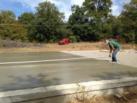
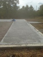
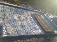
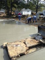
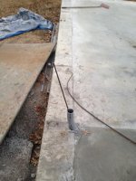
Once the fill was in and level I installed keyway to separate the placements. This was done for several reasons but the main one was so that I and a couple of friends or family could work the concrete. I installed the vapor barrier and rebar and was ready to go. The blue barrier is my old pool liner that I had to replace earlier this year. We skreeded it off with a 20 ft 2x6, the placement was 20 x 40 minus the stem walls(1 foot) so 19 x 38. It used up 10yards pretty quickly. Many thanks to the guys from work for helping work the pad.
We vibrated the edges and the keyway.
 

Attachments

  • IMG_1361 (Copy).JPG
    IMG_1361 (Copy).JPG
    57.6 KB · Views: 79
  • IMG_1360 (Copy).JPG
    IMG_1360 (Copy).JPG
    39.9 KB · Views: 79
  • IMG_1358 (Copy).JPG
    IMG_1358 (Copy).JPG
    35.3 KB · Views: 76
  • IMG_1905 (Copy).JPG
    IMG_1905 (Copy).JPG
    34.2 KB · Views: 94
  • IMG_1937 (Copy).JPG
    IMG_1937 (Copy).JPG
    74.1 KB · Views: 85
  • IMG_1938 (Copy).JPG
    IMG_1938 (Copy).JPG
    67.9 KB · Views: 87
OP
4

48flatbed

Active member
Joined
Mar 8, 2007
Messages
44
Location
Hills of Arkansas
More of the first placement. That's me working the float. A couple hours later I put on my power-trowel and smoothed it out. I troweled it 3 times 1 hour apart. It is a great feeling to walk out and see some floor!! :)
This first placement was 10 yards @ $1201

previous totals:
Material $1515 Concrete $1900
adding this placement $1201

total materials $1515 total concrete $3101
Running total $4616
 

Attachments

  • IMG_1943 (Copy).JPG
    IMG_1943 (Copy).JPG
    27.3 KB · Views: 80
  • IMG_1942 (Copy).JPG
    IMG_1942 (Copy).JPG
    38.3 KB · Views: 83
  • IMG_1941 (Copy).JPG
    IMG_1941 (Copy).JPG
    72.9 KB · Views: 84
  • IMG_1940 (Copy).JPG
    IMG_1940 (Copy).JPG
    83 KB · Views: 86
  • IMG_1939 (Copy).JPG
    IMG_1939 (Copy).JPG
    68.8 KB · Views: 79
OP
4

48flatbed

Active member
Joined
Mar 8, 2007
Messages
44
Location
Hills of Arkansas
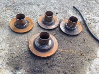
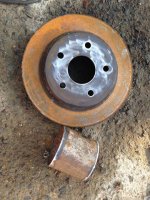
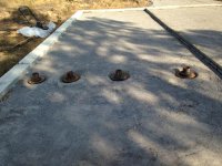
Here is how I made my anchor points. I took some big truck rotors (16-17 in diameter) and some 5 inch tubing. I welded the tubing to the rotors then filled in the stud holes. Then I welded some 3/4 in stock across the opening under the tubing. I put a clevis on the stock.
 

Attachments

  • IMG_1950 (Copy).JPG
    IMG_1950 (Copy).JPG
    97.6 KB · Views: 74
  • IMG_1948 (Copy).JPG
    IMG_1948 (Copy).JPG
    50.5 KB · Views: 62
  • IMG_1947 (Copy).JPG
    IMG_1947 (Copy).JPG
    50.5 KB · Views: 52
OP
4

48flatbed

Active member
Joined
Mar 8, 2007
Messages
44
Location
Hills of Arkansas
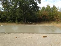
The anchor points were installed in the 2nd floor placement I dug out a circle large enough to sink them in so that the top of the tubing is flush with the floor. This placement was 12x40 (plus and unexpected 10x10 ramp). The truck had 4 yards more than I had asked for, since it was there, and he cut off the delivery charge and the fuel charge, I took it. The ramp is to the right in the picture of the floor. That is the back of the building.
 

Attachments

  • IMG_1962 (Copy).JPG
    IMG_1962 (Copy).JPG
    31.6 KB · Views: 112
  • IMG_1961 (Copy).JPG
    IMG_1961 (Copy).JPG
    27.7 KB · Views: 93
  • IMG_1960 (Copy).JPG
    IMG_1960 (Copy).JPG
    29.1 KB · Views: 86
  • IMG_1958 (Copy).JPG
    IMG_1958 (Copy).JPG
    27.9 KB · Views: 95
  • IMG_1952 (Copy).JPG
    IMG_1952 (Copy).JPG
    40 KB · Views: 106
  • IMG_1951 (Copy).JPG
    IMG_1951 (Copy).JPG
    64.6 KB · Views: 110
OP
4

48flatbed

Active member
Joined
Mar 8, 2007
Messages
44
Location
Hills of Arkansas
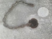
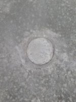
some more pics of the anchor points. These will allow me to tie things down and then jack between the anchors. That lets you straighten car frames, trailers etc. There is a chain hooked to the clevis. When not in use the chain stores inside and is covered. The concrete was still damp in these pictures causing that mottled look.

Previous - materials cost $1515 Concrete $3101
Rebar and plastic $430 -concrete $1012
new totals - materials $1945 Concrete $4113
running total $6058
 

Attachments

  • IMG_1963 (Copy).JPG
    IMG_1963 (Copy).JPG
    49 KB · Views: 59
  • IMG_1964 (Copy).JPG
    IMG_1964 (Copy).JPG
    26 KB · Views: 63
  • IMG_1961 (Copy).JPG
    IMG_1961 (Copy).JPG
    27.7 KB · Views: 63
Last edited:
OP
4

48flatbed

Active member
Joined
Mar 8, 2007
Messages
44
Location
Hills of Arkansas
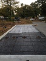
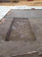
This next placement occurred on 11-11-2016. In the first picture the green area is to be a recess for my scissor lift. If you look closely at the stemwall you can see little piles of dust where I drilled in order to install rebar. I've done this on all the previous placements but forgot to mention it. The next pic shows the hole dug out for the recess, it was sized to allow a 5 inch recess and still have 5 inch floor thickness below the recess and on the sides. The next pic show two 3' x 3' holes 12 inches deep. These are the thick spots for a two post lift. You can see me putting the HF bender to use bending rebar for the lift recess and for the two post holes.
 

Attachments

  • IMG_1993 (Copy).JPG
    IMG_1993 (Copy).JPG
    35.2 KB · Views: 60
  • IMG_1969 (Copy).JPG
    IMG_1969 (Copy).JPG
    49.3 KB · Views: 58
  • IMG_1992 (Copy).JPG
    IMG_1992 (Copy).JPG
    64.1 KB · Views: 63
  • IMG_1999 (Copy).JPG
    IMG_1999 (Copy).JPG
    44.3 KB · Views: 56
  • IMG_2001 (Copy).JPG
    IMG_2001 (Copy).JPG
    54.1 KB · Views: 66
  • IMG_2003 (Copy).JPG
    IMG_2003 (Copy).JPG
    21.6 KB · Views: 54
OP
4

48flatbed

Active member
Joined
Mar 8, 2007
Messages
44
Location
Hills of Arkansas
more pics of this placement. There are a couple of pics of the recess form. I ran the ******** all around on top and under this form. Once the vibrating was done we placed rubble in it to keep it in place. In the next picture you can see the form for the start of a ramp on the side. The end piece can be slid up the rebar to whatever size is needed for the left over concrete in the truck. After the size was determined The end piece was screwed in place and rebar was put in across the form.
 

Attachments

  • IMG_2004 (Copy).JPG
    IMG_2004 (Copy).JPG
    27 KB · Views: 49
  • IMG_2006 (Copy).JPG
    IMG_2006 (Copy).JPG
    77.5 KB · Views: 57
  • IMG_2007 (Copy).JPG
    IMG_2007 (Copy).JPG
    72.9 KB · Views: 52
  • IMG_2012 (Copy).JPG
    IMG_2012 (Copy).JPG
    45.5 KB · Views: 56
  • IMG_2011 (Copy).JPG
    IMG_2011 (Copy).JPG
    84.9 KB · Views: 58
  • IMG_2009 (Copy).JPG
    IMG_2009 (Copy).JPG
    45.8 KB · Views: 69
  • IMG_2008 (Copy).JPG
    IMG_2008 (Copy).JPG
    43.4 KB · Views: 53
OP
4

48flatbed

Active member
Joined
Mar 8, 2007
Messages
44
Location
Hills of Arkansas
The adjustable form worked well and made use of the extra concrete on the truck. I ran a piece of rebar through the raceway to clear out a bit of concrete that managed to get in there. This raceway is for the hydraulic hose to the lift. The finished placement with the recess. Even with all the vibrating the bottom surface wasn't perfect. At least it will be under the lift.
 

Attachments

  • IMG_2021 (Copy).JPG
    IMG_2021 (Copy).JPG
    31.4 KB · Views: 67
  • IMG_2020 (Copy).JPG
    IMG_2020 (Copy).JPG
    39.6 KB · Views: 52
  • IMG_2019 (Copy).JPG
    IMG_2019 (Copy).JPG
    36.6 KB · Views: 70
  • IMG_2018 (Copy).JPG
    IMG_2018 (Copy).JPG
    32.3 KB · Views: 50
  • IMG_2013 (Copy).JPG
    IMG_2013 (Copy).JPG
    41.7 KB · Views: 53
OP
4

48flatbed

Active member
Joined
Mar 8, 2007
Messages
44
Location
Hills of Arkansas
That brings it up to date. Progress now will slow way down as I am doing this by myself most of the time.

previous: materials $1945 Concrete $4113
materials added $18 Concrete $1052
Totals: materials cost $1963 Concrete $5165

Running total $7128
 
OP
4

48flatbed

Active member
Joined
Mar 8, 2007
Messages
44
Location
Hills of Arkansas
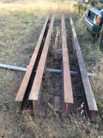
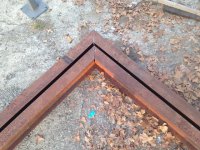
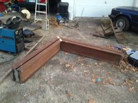
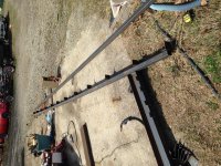
One of the Craigslist finds at the end of 2015 was some I beams. I bought 4 W-beam 10x22 ('W'ide flange -10 inches high - 22 pounds per foot 3/8 flange) 20 feet long, and 3 W12x35 20feet long and 1 8in structural channel 15 feet long = all for $400!! The first pic is the first load. This will be used to build a bridge crane and a TUMS.

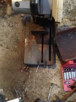
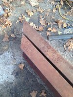
Tooling Universal Mounting System (TUMS sounded better than UTMS). In my present small shop I have threaded anchors in the floor to mount things (tire changer, metal benders, rollers etc.) but after a few uses they pull out of the floor and new locations or larger anchors must be used. This is my way of solving this problem. First I cut one of the W10x22 beams in four pieces with a 45 on one end of each. My chopsaw cut it in half ok by removing the clamp, cutting through one side then flipping the saw to finish the cut. The 45s had to be cut with a 9" hand grinder with a cutoff blade attached.
 

Attachments

  • IMG_1044 (Copy).JPG
    IMG_1044 (Copy).JPG
    57.2 KB · Views: 46
  • IMG_2028 (Copy).JPG
    IMG_2028 (Copy).JPG
    38.5 KB · Views: 42
  • IMG_2038 (Copy).JPG
    IMG_2038 (Copy).JPG
    51 KB · Views: 41
OP
4

48flatbed

Active member
Joined
Mar 8, 2007
Messages
44
Location
Hills of Arkansas
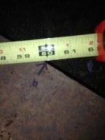
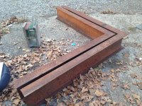
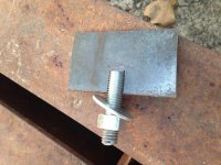
Next I welded the beams together with a 1 inch gap between them. The ends are capped to hold them at the proper distance and to keep concrete from filling it up. This will be set in the floor with the top surface flush with the concrete floor. The third pic is the squareness check - anybody who knows the 3,4,5 rule can see I got pretty close to perfect. The last pic is an unwelded hold down bolt. I had a little video demonstrating it but I don't know how to load it. basically you drop the T-bolt in the slot, turn it 90 degrees and it cant come out. This will accommodate up to a one inch T-bolt. The size of the metal for the T part would be close to the bolt size ie: 3/4 inch thick 3 inch strap for a 1 inch bolt.
 

Attachments

  • IMG_2045 (Copy).JPG
    IMG_2045 (Copy).JPG
    17.9 KB · Views: 36
  • IMG_2040 (Copy).JPG
    IMG_2040 (Copy).JPG
    87.4 KB · Views: 38
  • IMG_2039 (Copy).JPG
    IMG_2039 (Copy).JPG
    82.6 KB · Views: 38
  • IMG_2047 (Copy).JPG
    IMG_2047 (Copy).JPG
    60.7 KB · Views: 39
  • IMG_2041 (Copy).JPG
    IMG_2041 (Copy).JPG
    58.2 KB · Views: 37

cros13

Well-known member
Joined
Sep 29, 2014
Messages
496
Location
Sydney, Australia
Subscribed! Great thread mate.

You got that concrete for a decent price, I'm looking to have to pay around $5800 AUD, ($4500 usd) for my slab, and its only a 22x22! that was the cheapest quote too.

I really like your shop truck too!
 
To avoid these ads, REGISTER NOW!

rusty1

Well-known member
Joined
Feb 6, 2009
Messages
518
Location
No. Illinois
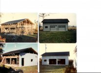
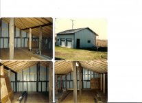
...really like your build and the way you're doing it,...did something similiar back in '85,...used my 52 Chevy p.u. almost entirely to build my 26x32 barn,...
poured the crete with help from friends, built all the 2x6 stud walls from used lumber I got by taking down a corn crib,..rest of materials were new cept garage doors. Other than help with concrete and roof sheeting, I built the building by myself in 1 month.
barn build.jpg

barn build 001.jpg

barn build 002.jpg
 

nterry1957

Well-known member
Joined
Apr 3, 2014
Messages
118
Location
SW Missouri the garden spot of the USA
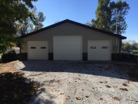
Hey Flat! Great job! I'm guessing you are somewhat of a neighbor of mine. I built my shop mostly from decommissioned poultry house material. My wife insisted on new metal for the exterior but the rest of it is all CL finds!
Glad to see your project coming along and looking forward to seeing it finished.
Here is a couple pics of mine and a link to the build thread.

I've got about $13,000 in mine for a 40x40. (dirt work and all)

http://www.garagejournal.com/forum/showthread.php?t=329478
 

Attachments

  • IMG_3003.jpg
    IMG_3003.jpg
    150 KB · Views: 37
  • 3007.jpg
    3007.jpg
    42.9 KB · Views: 33
Last edited:
OP
4

48flatbed

Active member
Joined
Mar 8, 2007
Messages
44
Location
Hills of Arkansas
Its been awhile since I posted as winter slowed things down a bit. But some unusually nice February weather has allowed me to make a little progress.

@ cros13, rusty1, tvtaurus and nterry: Thanks for the nice comments and the subscritions! It is taking me much more than a month (and will continue to be slow) but it is getting done a little at a time.

Jon
 
OP
4

48flatbed

Active member
Joined
Mar 8, 2007
Messages
44
Location
Hills of Arkansas
I pulled the marklift out and got it all running again. I used it to do the truss setting. I was taking pictures along the way but somehow I lost some of them.
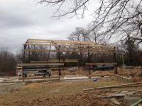
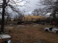
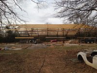
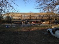
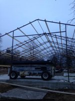
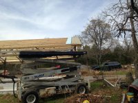
The process was to lift the peak end of the truss onto the lift, attach a board onto the top of the wall section. After lifting the wall side of the truss I bolted together the peak. Then I attached a 20 ft 2x6 to the lower of the two top wall purlin plates. Next I walked it up raising the lift a few feet and lifting each side a few feet and driving the lift forward. Once standing they were tied into the top with 2x10 purlins (these were the ones recycled from the forms hince the concrete staining on them). It took about 2 hrs from start to finish to stand the truss, hang the bands and bolt in the 'X' braces.
 

Attachments

  • IMG_2212 (Copy).JPG
    IMG_2212 (Copy).JPG
    60.8 KB · Views: 34
  • IMG_2211 (Copy).JPG
    IMG_2211 (Copy).JPG
    82 KB · Views: 29
  • IMG_2210 (Copy).JPG
    IMG_2210 (Copy).JPG
    83.7 KB · Views: 29
OP
4

48flatbed

Active member
Joined
Mar 8, 2007
Messages
44
Location
Hills of Arkansas
The 2x10 band purlins are 20 feet long and the joints are staggered. I installed a 10 foot board first to start the stagger and then I was able to handle the 20 foot ones by myself as well by hanging them with a short piece of 1x2 in the middle. This allowed me to move the board around to where it needed to be without having to hold its weight. One of the pics is a shot of the 'X' braces made of half inch rebar. There will be an x brace everywhere there is not a garage door, overkill I know but I like overkill. And the rebar was leftover from the footing pour so is free for this job!

Next I started installing the roof purlins. They are 20 foot 2x6 not treated. The joints are staggered here as well. I also bought several 12 foot 2x6 to start the stagger and give me and eave extension. These pictures also show 2x4 cross braces in the roof and the angle iron braces from the bottom truss member up to the roof purlin (only the necessary purlins were up in this pic but there are now purlins every two feet). The engineering drawings don't call for the 2x4 cross braces and only call for half as many angle iron braces but once again I like overkill. As of today I have half my trusses up and about half my roof purlins.
 

Attachments

  • IMG_2214 (Copy).JPG
    IMG_2214 (Copy).JPG
    77.9 KB · Views: 30
  • IMG_2215 (Copy).JPG
    IMG_2215 (Copy).JPG
    72.8 KB · Views: 29
  • IMG_2216 (Copy).JPG
    IMG_2216 (Copy).JPG
    77.2 KB · Views: 28
  • IMG_2217 (Copy).JPG
    IMG_2217 (Copy).JPG
    89.9 KB · Views: 27
  • IMG_2225 (Copy).JPG
    IMG_2225 (Copy).JPG
    81.1 KB · Views: 30
OP
4

48flatbed

Active member
Joined
Mar 8, 2007
Messages
44
Location
Hills of Arkansas
Previous - materials cost $1963 Concrete $5165
materials added 2x6x20 $334; 2x6x12 $184; 2x4x20 $59 total= $577
New Totals: materials cost $2540 Concrete $5165

Running total: $7705
 

jp828108

Well-known member
Joined
Jun 28, 2011
Messages
484
Location
Ohio
Looking good so far, and that money investment total looks nice too. Looking forward to seeing what else you come up with.

jp
 
OP
4

48flatbed

Active member
Joined
Mar 8, 2007
Messages
44
Location
Hills of Arkansas
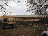
Once again its been awhile since my last update but things have been moving forward. The first two pictures show the last of the engineered trusses standing and purlins attached. The next pics show the final beam truss I built so I had room to mount an evac fan in the wall above the bridge crane that will be on this end. There is a pic of all the plates and hangers need to attach wall and roof purlins. That was 168 holes to drill! The next is of one half of the beam truss. The roof load is transferred to the vertical supports.
 

Attachments

  • IMG_2238 (Copy).JPG
    IMG_2238 (Copy).JPG
    83.6 KB · Views: 26
  • IMG_2244 (Copy).JPG
    IMG_2244 (Copy).JPG
    72.5 KB · Views: 23
  • IMG_2246 (Copy).JPG
    IMG_2246 (Copy).JPG
    96.3 KB · Views: 26
  • IMG_2242 (Copy).JPG
    IMG_2242 (Copy).JPG
    61.3 KB · Views: 24
  • IMG_2247 (Copy).JPG
    IMG_2247 (Copy).JPG
    83.1 KB · Views: 23
  • IMG_2258 (Copy).JPG
    IMG_2258 (Copy).JPG
    76.8 KB · Views: 20
  • IMG_2259 (Copy).JPG
    IMG_2259 (Copy).JPG
    35.6 KB · Views: 30
OP
4

48flatbed

Active member
Joined
Mar 8, 2007
Messages
44
Location
Hills of Arkansas
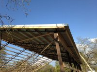
Now I 'get' to start installing the insulation and the metal on the roof! Remember this is the used metal that I got for $350 This metal came from a church building and is 26 feet long. My roof with the overhang is 23'3" long so each piece had to be cut. I used a regular skill saw with a metal cutting blade. It is quick and easy. The foam board is 4' by 21' so it is perfect to cover the inside of the building and leaves the overhang uninsulated. It is 1.5 inches thick so I used 2x8 end purlins to end up with the same height as the 2x6 purlin with the 1.5 in insulation. The added benefit is that makes the screws in the end of the metal 100% in wood. I used the same 3' screws here.
The first pic is of the first piece of metal up. The last pic is of the temporary installation of the rake trim. This will be removed and reinstalled once the ends of the metal are trimmed straight. (I left them long to allow trimming to a straight line). The rake trim was temporarily installed to prevent wind from getting under the sides of the metal.
 

Attachments

  • IMG_2276 (Copy).JPG
    IMG_2276 (Copy).JPG
    69.6 KB · Views: 23
  • IMG_2277 (Copy).JPG
    IMG_2277 (Copy).JPG
    81.9 KB · Views: 24
  • IMG_2281 (Copy).JPG
    IMG_2281 (Copy).JPG
    98.7 KB · Views: 27
  • IMG_2282 (Copy).JPG
    IMG_2282 (Copy).JPG
    62.2 KB · Views: 33
OP
4

48flatbed

Active member
Joined
Mar 8, 2007
Messages
44
Location
Hills of Arkansas
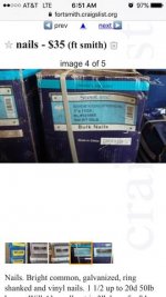
Another Craigslist find was nails to install the foam board. $35 for a 50lbs box!

Previous - materials cost $2540 Concrete $5165
materials added 2x6x20 $334; 2x8x10 $116; steel for beam truss $139; screws $99 ; Nails $35
New Totals: materials cost $3263 Concrete $5165

Running total: $8428
 

Attachments

  • IMG_2251j (Copy).jpg
    IMG_2251j (Copy).jpg
    26.1 KB · Views: 36
To avoid these ads, REGISTER NOW!
Top Bottom