To avoid these ads, REGISTER NOW!

The Everything 3D Printer Thread

Citation

Well-known member
Joined
Jan 20, 2016
Messages
3,230
Location
Indy
I've been using Solidworks off and on since SW'97. Currently you can get the 3D experience for about $50/year. It's basically SW with a horribly annoying software launcher.

There is a SW "mountain board" PDF on the Web that's a training guide for the program. It's old but still a good guide. It was something SW did for schools a while back. Easy to find with a web search.
 
To avoid these ads, REGISTER NOW!

gamescastspencer

Well-known member
Joined
Apr 4, 2016
Messages
167
Location
Saint Peters, MO
I used to use Fusion and even considered paying for a license, then I discovered that Solid Works offers a makers version for $50/year. They often run sales for 1/2 off.

At $25 for a year, I think it’s an excellent value, even at $50 it’s worth it. It seems that fusion keeps rising in price, I think it was ~$360 for a year when I last looked before going to SW, I see it’s $510 for a year with 25% off, $680 regular.
 

coldh2o

Well-known member
Joined
May 21, 2013
Messages
1,449
Location
Ontario, Canada
I used to use Fusion and even considered paying for a license, then I discovered that Solid Works offers a makers version for $50/year. They often run sales for 1/2 off.

At $25 for a year, I think it’s an excellent value, even at $50 it’s worth it. It seems that fusion keeps rising in price, I think it was ~$360 for a year when I last looked before going to SW, I see it’s $510 for a year with 25% off, $680 regular.

I struggle with Fusion, don't find it very intuitive. Is it difficult to transition to Solid Works?
 

mike93lx

ALLIANCE MEMBER
Joined
Dec 9, 2013
Messages
38,119
Location
Richmond, VA
I was trying to find a thread that I swear we started last time this came up, so we could keep this thread focused on the 3D printer side, and address CAD separately. However, I can't find it specifically (some related ones, but not a definite). Maybe it ended up getting snipped due to egos? Happy to post here as well, but worried about it getting buried within the 170 pages.

Overall, I find Fusion less intuitive than OnShape/Solidworks, but that may be because of what I learned first (Dassault vs Autodesk is like Windows/Mac). Happy to help with any program though.
The issues I encounter tend to be more a desire to do things more efficiently. I manage to find a way to brute force my way to a result, but when I look back at the time line, I cringe.
 
Last edited:

mike93lx

ALLIANCE MEMBER
Joined
Dec 9, 2013
Messages
38,119
Location
Richmond, VA
I used to use Fusion and even considered paying for a license, then I discovered that Solid Works offers a makers version for $50/year. They often run sales for 1/2 off.

At $25 for a year, I think it’s an excellent value, even at $50 it’s worth it. It seems that fusion keeps rising in price, I think it was ~$360 for a year when I last looked before going to SW, I see it’s $510 for a year with 25% off, $680 regular.
I just use it personally, so I'm on a free personaly/hobbyist license. It doesn't have every feature, but I haven't run into a problem
 

Cruzan80

Well-known member
Joined
Jul 22, 2015
Messages
4,359
Location
Denver, CO
I struggle with Fusion, don't find it very intuitive. Is it difficult to transition to Solid Works?
Depends on what you are struggling with. They are both parametric CAD, but they "flow" differently.

OnShape is 90+% Soldworks alike (for the basic features), besides small UI things like a floating window vs a sidebar, and navigation keys.

You would lose your "feature history" moving existing files to the new program.
 

gamescastspencer

Well-known member
Joined
Apr 4, 2016
Messages
167
Location
Saint Peters, MO
I struggle with Fusion, don't find it very intuitive. Is it difficult to transition to Solid Works?
Maybe? Cruzan beat me to a reply, functionally they are fairly similar, being both parametric. The workflow and environments are somewhat different.

In trade school (PMT/Precision Machining Technology) we started on Mastercam doing both modeling and cam, then switched to solid works for modeling and continuing with mastercam for the cam. That was a big change as mastercam is direct, not parametric, but once acclimated most of us much preferred SW over MC there was a few that wanted to stick to MC for modeling. Learning to make use of and take advantage of the parametric capabilities and relationships was a big thing.

Personally I can wade my way through fusion but I like using SW much more. One I have a formal education and training on, and the other is YouTube university, so that certainly influences things too. Both are extremely capable and powerful in the right hands.
 

Cruzan80

Well-known member
Joined
Jul 22, 2015
Messages
4,359
Location
Denver, CO
OnShape is 90+% Soldworks alike (for the basic features), besides small UI things like a floating window vs a sidebar, and navigation keys.
Sorry, realized I only typed half of what I thought. Since OnShape is free, but SW costs money, I would try OnShape to see if you like it better than Fusion. The main difference between OnShape/SW comes with assemblies (they are handled vastly differently). OnShape also has a CAM feature that should be rolling out soon (was in Beta last spring).

Solidworks does have a CAM feature set, but it is fairly involved compared to Fusion.
 

Cruzan80

Well-known member
Joined
Jul 22, 2015
Messages
4,359
Location
Denver, CO
It means that all of the "rules" for a design are drawn with math in mind, and so you can "travel back in time" and adjust one thing in the design history, and when you return to the "present/future", the rest of the steps were done using that new data point. So if I said the hole was 5mm from the edge, and then I changed it to 10mm from the edge, all of the other steps would still move forward. If the original design had a lip, the first version could have a partial cutout, but the second would be solid.

Drawn with math means that it has numeric dimensions and relations (parallel, concentric, tangent, etc).
 

mike93lx

ALLIANCE MEMBER
Joined
Dec 9, 2013
Messages
38,119
Location
Richmond, VA
If you click on those parametric files in makerworld, it will provide dimensions that you can change and then print.

I just figured out how to share models that way myself and did it with the bottle lanyard/carrier I posted a little bit back, also with a dashcam mount I designed

8946.jpg
 

Cruzan80

Well-known member
Joined
Jul 22, 2015
Messages
4,359
Location
Denver, CO
Yes, the "short" version of what those "parametric files" are doing is replacing the numeric dimension with a variable ("X"), and then because of the way it is computed, changing X allows you to not have to edit the sketch or feature directly, but simply call up a table where each variable is listed, and change it there. The computer then "recalculates" the entire history, updating each variable as it comes across it.

@mike93lx , I am sure this is stuff you already know, trying to give greater context on how that ties in with my earlier post for those following along at home.


Seems like I am thinking about 1.5-2x what I am actually saying out loud or typing today... Sorry, guys.
 
To avoid these ads, REGISTER NOW!

mike93lx

ALLIANCE MEMBER
Joined
Dec 9, 2013
Messages
38,119
Location
Richmond, VA
Yes, the "short" version of what those "parametric files" are doing is replacing the numeric dimension with a variable ("X"), and then because of the way it is computed, changing X allows you to not have to edit the sketch or feature directly, but simply call up a table where each variable is listed, and change it there. The computer then "recalculates" the entire history, updating each variable as it comes across it.

@mike93lx , I am sure this is stuff you already know, trying to give greater context on how that ties in with my earlier post for those following along at home.


Seems like I am thinking about 1.5-2x what I am actually saying out loud or typing today... Sorry, guys.
I learned about parametric design a whopping couple months ago and the ability to post files with parameter favorites a whole three days ago entirely by accident 😂

Bow down to my CAD prowess!
 

Cruzan80

Well-known member
Joined
Jul 22, 2015
Messages
4,359
Location
Denver, CO
At least in O Shape/Solidworks, the term used is "Design Table" or "Global Variables" depending on how you are entering stuff. Not sure what Fusion calls them.

PS. Yes, I know you can do much more with a Design Table in SW, keeping it simple for those just learning.
 

mike93lx

ALLIANCE MEMBER
Joined
Dec 9, 2013
Messages
38,119
Location
Richmond, VA
At least in O Shape/Solidworks, the term used is "Design Table" or "Global Variables" depending on how you are entering stuff. Not sure what Fusion calls them.

PS. Yes, I know you can do much more with a Design Table in SW, keeping it simple for those just learning.
I believe the menu selection is "edit parameter". You then look through all the sketches, bodies, components, etc in the file that have parameters and can favorite (which is what bambu studio looks for to make it easily editable in their website) or edit them there.

I need to look into how to name them as the model is built to make referencing easier.

When dimensioning a part, you can enter a reference to another dimension at that point. I presume the same in onshape/sw
 

Cruzan80

Well-known member
Joined
Jul 22, 2015
Messages
4,359
Location
Denver, CO
Yes, that is also possible. But as you discovered, very clunky. It is usually D2@Sketch4, where it has no real relation to anything making sense outside of itself.

For both SW/OS, there is an area where you can define variables to start (OnShape is on the right, SW has it hidden by default in the feature tree, but can be shown). In SW (can't remember if OS allows this) you can also simply put in ="X" when dimensioning, and it will ask you if you want to make a new global variable "X". The trick is that the second option only allows for direct numeric input, so I can't make "X" to equal "Y"/2 using that way.

For both, anything without spaces works, so I can call variables "tooldiameter", "plythickness" etc (can you tell the first use students had was with a wood CNC router?)
 

burger

Well-known member
Joined
Jun 6, 2005
Messages
1,007
Location
Erf
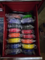
I considered cereal boxes early on (even posted here about it) and decided that the bulk and handling wasn't worth it for me. I have driers on both of my ams's as well as a standalone, plus I don't tend to keep a ton of filament around. My tool chest, which is my printer stand, has a couple drawers that perfectly fit filament spools, so I've just been doing the ziplocs for now. The Pic below is one drawer, but it was right before starting a wheelchair so it's packed. 8214.jpg

I recognize that drawer. Mine has the plastic drill/driver organizer.
 

burger

Well-known member
Joined
Jun 6, 2005
Messages
1,007
Location
Erf
It means that all of the "rules" for a design are drawn with math in mind, and so you can "travel back in time" and adjust one thing in the design history, and when you return to the "present/future", the rest of the steps were done using that new data point. So if I said the hole was 5mm from the edge, and then I changed it to 10mm from the edge, all of the other steps would still move forward. If the original design had a lip, the first version could have a partial cutout, but the second would be solid.

Drawn with math means that it has numeric dimensions and relations (parallel, concentric, tangent, etc).

That's a very good explanation. I used to daily drive Solidworks. At this point I figure out what needs to be figured out, and then how to figure that out.
 

Cruzan80

Well-known member
Joined
Jul 22, 2015
Messages
4,359
Location
Denver, CO
I won a Kearney and Trecker dividing head model H at the same auction I won my Hardinge HC, but it only came with plate 3 for indexing.

Went through the manual and found the indexing hole counts for the remaining 6. Running a rough-cut at #1 now.

Indexing head plates.png
But did you use parametric variables for the hole layouts? :evil:
 

Jehannum

Well-known member
Joined
May 3, 2012
Messages
1,381
Location
Albuquerque, NM
But did you use parametric variables for the hole layouts? :evil:
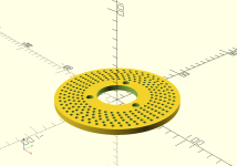
I use openscad.

So, sort of?

Code:
//dividing head plates
diameter = 5.370;
height = .250;
centerbore = 1.752;
bolt = 2.370;
bolt_dia = .3225;
bolt_head_dia = .455;
bolt_head_depth = .158;
pin = 0.136;
$fn = 360;
cf = 25.4;
id = 3;
od = 5.25;
//tracks
// 1
tracks = [37, 39, 41, 43, 47, 49];
// 2
// tracks = [21, 23, 27, 29, 31, 33];
// 3
// tracks = [12, 15, 17, 19, 19, 20];
// 4
// tracks = [57, 67, 77, 87, 97];
// 5
// tracks = [53, 63, 73, 83, 93];
// 6
// tracks = [51, 61, 71, 81, 91];
// 7
// tracks = [48, 59, 69, 79, 89. 99];

main();

//index holes
module hole() {
  translate([0, 0, -1]) {
    cylinder(h = height * cf + 2, d = pin * cf);
  }
}

//bolt holes (countersunk head)
module boltHoles () {
  for (i = [0:2]) {
    rotate([0, 0, (360/3)*i]) {
      translate([(bolt/2)*cf, 0, -1]) {
        union() {
          translate([0, 0, (height - bolt_head_depth)*cf]) {
            cylinder(h = (bolt_head_depth + .003)*cf,
                     d = bolt_head_dia*cf);
          }
          cylinder(h = height*cf+2, d = bolt_dia*cf);

        }
      }
    }
  }
}

//creates a single row around the blank
module pinHoles(index) {
  spacing = (od/2 - id/2)/len(tracks);
  for (j = [1:tracks[index]]) {
    rotate([0, 0, (360/tracks[index])*j]) {
      translate([(id/2 + (spacing*index))*cf, 0, 0]) {
        hole();
      }
    }
  }
}


module main() {
  difference() {
    cylinder(h = height*cf, d = diameter*cf);
    translate([0,0,-1]) {
      cylinder(h = height*cf + 2, d = centerbore*cf);
    }
    boltHoles();
 
    for(i = [0:len(tracks)-1]) {
      pinHoles(i);
    }
  }
}

When I'm convinced I've got the spacing correct between rows of indexes, all I have to do is change the commented out lines for different "tracks" arrays (which are just the number of holes per row of indexes in the plate) and it'll automatically re-space the new holes for me.

I'll also dump the STLs on thingiverse so that people can just make 'em if they need 'em.
 

bugnut

ALLIANCE MEMBER
Joined
Jul 14, 2012
Messages
4,034
Location
Central Ohio
paging @jblnut you're gonna want these at some point in the future, bookmark this spot!

I won a Kearney and Trecker dividing head model H at the same auction I won my Hardinge HC, but it only came with plate 3 for indexing.

Went through the manual and found the indexing hole counts for the remaining 6. Running a rough-cut at #1 now.

I use openscad.

So, sort of?

Code:
//dividing head plates
diameter = 5.370;
height = .250;
centerbore = 1.752;
bolt = 2.370;
bolt_dia = .3225;
bolt_head_dia = .455;
bolt_head_depth = .158;
pin = 0.136;
$fn = 360;
cf = 25.4;
id = 3;
od = 5.25;
//tracks
// 1
tracks = [37, 39, 41, 43, 47, 49];
// 2
// tracks = [21, 23, 27, 29, 31, 33];
// 3
// tracks = [12, 15, 17, 19, 19, 20];
// 4
// tracks = [57, 67, 77, 87, 97];
// 5
// tracks = [53, 63, 73, 83, 93];
// 6
// tracks = [51, 61, 71, 81, 91];
// 7
// tracks = [48, 59, 69, 79, 89. 99];

main();

//index holes
module hole() {
  translate([0, 0, -1]) {
    cylinder(h = height * cf + 2, d = pin * cf);
  }
}

//bolt holes (countersunk head)
module boltHoles () {
  for (i = [0:2]) {
    rotate([0, 0, (360/3)*i]) {
      translate([(bolt/2)*cf, 0, -1]) {
        union() {
          translate([0, 0, (height - bolt_head_depth)*cf]) {
            cylinder(h = (bolt_head_depth + .003)*cf,
                     d = bolt_head_dia*cf);
          }
          cylinder(h = height*cf+2, d = bolt_dia*cf);

        }
      }
    }
  }
}

//creates a single row around the blank
module pinHoles(index) {
  spacing = (od/2 - id/2)/len(tracks);
  for (j = [1:tracks[index]]) {
    rotate([0, 0, (360/tracks[index])*j]) {
      translate([(id/2 + (spacing*index))*cf, 0, 0]) {
        hole();
      }
    }
  }
}


module main() {
  difference() {
    cylinder(h = height*cf, d = diameter*cf);
    translate([0,0,-1]) {
      cylinder(h = height*cf + 2, d = centerbore*cf);
    }
    boltHoles();
 
    for(i = [0:len(tracks)-1]) {
      pinHoles(i);
    }
  }
}
When I'm convinced I've got the spacing correct between rows of indexes, all I have to do is change the commented out lines for different "tracks" arrays (which are just the number of holes per row of indexes in the plate) and it'll automatically re-space the new holes for me.

I'll also dump the STLs on thingiverse so that people can just make 'em if they need 'em.
 

Jehannum

Well-known member
Joined
May 3, 2012
Messages
1,381
Location
Albuquerque, NM
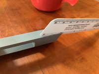
Second iteration on the design worked. The inner and outer tracks are reachable by the pin stop, and the lock holds everything well.

I might up the "fudge factor" a little bit, as the fits are a little tighter than I'd like, but releasing it is more of a case of letting the perfect be the enemy of the good.

PXL_20260725_191522010.jpg
 

Firebrick43

Well-known member
Joined
May 12, 2015
Messages
14,260
Location
West central Indiana
Second iteration on the design worked. The inner and outer tracks are reachable by the pin stop, and the lock holds everything well.

I might up the "fudge factor" a little bit, as the fits are a little tighter than I'd like, but releasing it is more of a case of letting the perfect be the enemy of the good.

PXL_20260725_191522010.jpg
I never would have thought about dividing plates but what a perfect application for a 3d printer. So much easier than machining new ones.

But for the love of god, put some shoes on in the shop, for the protection of your own feet and for our eyes.
 
To avoid these ads, REGISTER NOW!
Top Bottom