
BreeStephany
ALLIANCE MEMBER
I am in the process of improving upon the design of a buzz box magneto timer I made in A&P school by adding a few minor additions to the basic design.
The circuit is more or less a signal generator and amplifier which generates a signal and illuminates an LED in the event of an open circuit and does not when the circuit is closed.
View media item 68565
View media item 68566

LM556 IC pinout
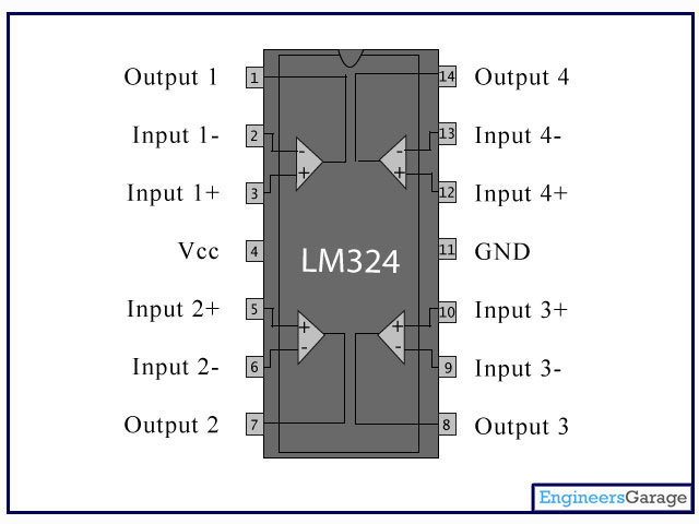
LM324 IC pinout
View media item 68567
View media item 68568
View media item 68569
View media item 68570
View media item 68571
View media item 68572
View media item 68573
View media item 68574
View media item 68575
View media item 68576
View media item 68577
View media item 68578
View media item 68579
View media item 68580
View media item 68581
View media item 68582
View media item 68583
View media item 68584
View media item 68585
I am hoping to improve upon the design by adding a potentiometer to control volume of both the speaker and a 3.5mm headphone jack which I would also like to add to circuit.
I am also looking into improving upon the signal generation to make a cleaner, better sounding signal, but that is likely for Buzz Box v3.0.
I am primarily doing a comprehensive thread over at HackaDay, but would love input from folks on GarageJournal if you feel you have any suggestions on how to go about the improvements or if you have suggestions for future improvements.
The circuit is more or less a signal generator and amplifier which generates a signal and illuminates an LED in the event of an open circuit and does not when the circuit is closed.
View media item 68565
View media item 68566
LM556 IC pinout
LM324 IC pinout
View media item 68567
View media item 68568
View media item 68569
View media item 68570
View media item 68571
View media item 68572
View media item 68573
View media item 68574
View media item 68575
View media item 68576
View media item 68577
View media item 68578
View media item 68579
View media item 68580
View media item 68581
View media item 68582
View media item 68583
View media item 68584
View media item 68585
I am hoping to improve upon the design by adding a potentiometer to control volume of both the speaker and a 3.5mm headphone jack which I would also like to add to circuit.
I am also looking into improving upon the signal generation to make a cleaner, better sounding signal, but that is likely for Buzz Box v3.0.
I am primarily doing a comprehensive thread over at HackaDay, but would love input from folks on GarageJournal if you feel you have any suggestions on how to go about the improvements or if you have suggestions for future improvements.
Last edited: