
Modern Garage
Well-known member
Hi all,
I'm building a foot control for my Miller Diversion TIG and am wondering, does anyone know which direction the potentiometer needs to be connnected? Should the resistance of the 1K pot increase or decrease as the pedal is depressed?
I could walk out to the garage and plug it in to test but it's currently 15 degrees out here in MN (up from 1F when I was eating breakfast) and I'm not sure my fingers would hold still long enough.
Joe
I'm building a foot control for my Miller Diversion TIG and am wondering, does anyone know which direction the potentiometer needs to be connnected? Should the resistance of the 1K pot increase or decrease as the pedal is depressed?
I could walk out to the garage and plug it in to test but it's currently 15 degrees out here in MN (up from 1F when I was eating breakfast) and I'm not sure my fingers would hold still long enough.
Joe

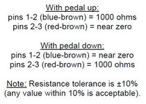
![1019231133a[1].jpg](/forum/data/attachments/1821/1821564-8acc51d8fa52674b8a0b2ec6984a04e9.jpg)