To avoid these ads, REGISTER NOW!

Ufer ground to sub-panel

mikeyr

Well-known member
Joined
Sep 16, 2005
Messages
1,971
Location
Santa Barbara, CA
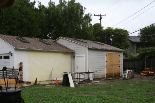
I had a extension built onto my detached garage and the city required a Ufer ground (something attached to the rebar in the concrete) even though the existing garage already had a 100amp sub-panel and was grounded through the main panel in the house.

In the confusion of trying to finish everything, the Ufer ground was never connected to the sub-panel. Its installation was signed off on the permit however AND I have a ground wire sticking out of my slab where the existing garage joins the new extension. I also have a inspector on his way for the final inspection, OOPS :) I am afraid the inspector will see the Ufer installation in the slab on the permit and will want to see it at the panel.

I was going to hook up the Ufer wire to the ground bar on the sub-panel but a friend said you can't have 2 grounds, its not safe so you have to change the wiring from the main panel to the sub before hooking up the Ufer. Since that does not sound right to me because my electrician had indicated it was easy to hook up, I thought I would ask here. I am trying to get my permit signed off today rather than have my electrician back next week and delay my FINAL inspection past this weekend because I want to move in this weekend.

Edit*** Done more reading on the web, all I know right now is that it was a existing sub-panel, I don't know if there were 3 wires or 4 wires to it from the house main, I will look in a few minutes. From what I remember, the neutral and ground bars in the existing sub were connected together but I really did not touch the electrical so I am not sure. From memory I think there is only 3 wires coming out of the conduit to the sub-panel.***

Any ideas ?
 
Last edited:
To avoid these ads, REGISTER NOW!
OP
M

mikeyr

Well-known member
Joined
Sep 16, 2005
Messages
1,971
Location
Santa Barbara, CA
Well the inspector did not show up...but he will be here in the morning.

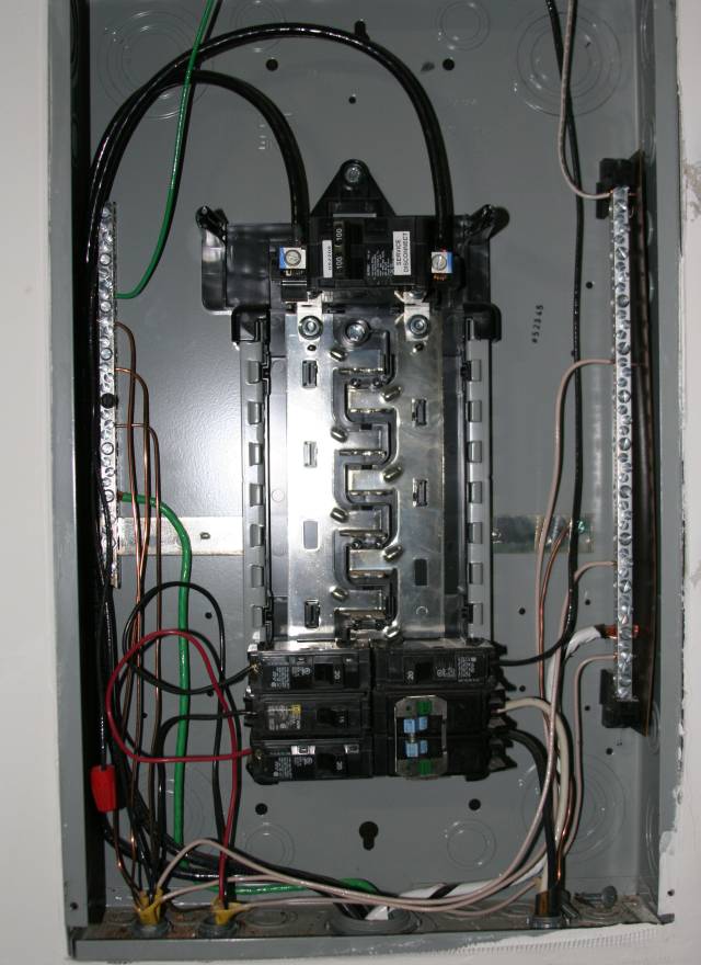
I am pretty sure I just take the Ufer ground wire and connect it to the ground bar on the LEFT of the panel. I was WRONG when I said the neutral and ground bars were connected together.

Coming out of the conduit from the main panel is 4 wires, 2 blacks, 1 black with white spiral (tape) and one green wire. The 2 blacks power the panel, the black&white goes to the right side and is neutral I am guessing, the green goes to the right and that is where I should connect the ufer ? right ? That would mean 2 grounds which my friend said is a bad thing to do, but he could not explain why its bad. If I can get this resolved, then I will fail inspection and I will have to wait yet another week to move after my electrician comes and fixes, this should be EASY I just don't want to try it without some idea of what I am doing.

IMG_3377.jpg
 
Last edited:
OP
M

mikeyr

Well-known member
Joined
Sep 16, 2005
Messages
1,971
Location
Santa Barbara, CA
Ok, I did not do that and not sure what you said :) but I will switch it out before the morning. That I can do :)

I was not able to get my electrician over here today so still hoping for a answer on the Ufer part. To be completely honest, I would rather my electrician remain FIRED rather than me putting my tail between my legs and calling him over. If I could get him to fix the Ufer before the inspector shows up that would be ok, but if not I will find a new electrician next week for the Ufer. I am pretty sure I know what to do just want to confirm it.
 

Stargeezer

Well-known member
Joined
Jan 12, 2009
Messages
347
Location
Central Nevada, USA
My electrician is grounding everything. #4 solid ground wire from pole underground to sub panel bus in garage, then grounded to rebar stub coming from under slab, and then also grounded to steel building framework. Everything is grounded. Don't understand how this would be bad..so I'll ask him this weekend..
 
Last edited:

rinny_tin_tin

Well-known member
Joined
Dec 20, 2008
Messages
636
Location
Northern Virginia
I had a extension built onto my detached garage and the city required a Ufer ground (something attached to the rebar in the concrete) even though the existing garage already had a 100amp sub-panel and was grounded through the main panel in the house.

In the confusion of trying to finish everything, the Ufer ground was never connected to the sub-panel. Its installation was signed off on the permit however AND I have a ground wire sticking out of my slab where the existing garage joins the new extension. I also have a inspector on his way for the final inspection, OOPS :) I am afraid the inspector will see the Ufer installation in the slab on the permit and will want to see it at the panel.

I was going to hook up the Ufer wire to the ground bar on the sub-panel but a friend said you can't have 2 grounds, its not safe so you have to change the wiring from the main panel to the sub before hooking up the Ufer. Since that does not sound right to me because my electrician had indicated it was easy to hook up, I thought I would ask here. I am trying to get my permit signed off today rather than have my electrician back next week and delay my FINAL inspection past this weekend because I want to move in this weekend.

Edit*** Done more reading on the web, all I know right now is that it was a existing sub-panel, I don't know if there were 3 wires or 4 wires to it from the house main, I will look in a few minutes. From what I remember, the neutral and ground bars in the existing sub were connected together but I really did not touch the electrical so I am not sure. From memory I think there is only 3 wires coming out of the conduit to the sub-panel.***

Any ideas ?

Connect yer UFER stub to the ground bar on the left (the one with all the bare wires on it) with No. 6 or 8 ground wire. Usually, in residential settings, a *detached* structure taking power via a subpanel from the main structure is supposed to have its own ground rod/ufer, etc -- however, no main bonding jumper installed between the ground bus and the neutral bus. However, if the grounds and neutrals are common (older construction) on one bus at the main, your at the mercy of the inspector's interpretation - in which case, he may make you install a bonding jumper at the subpanel.
 

octavio3311

Well-known member
Joined
Feb 4, 2009
Messages
61
Location
Brookfield, Ct
The 2 blacks feed the panel. The black with white spriral tape is the neutral - that goes to the right. The green is the ground - that goes to the left.
The UFER ground should also go to the left. I take it your electrician didn't leave you a UFER set-up outside - go to Home Depot and pick up a copper ground rod and 2 acorns (they'll know what you're talking about) and start hammering that baby into the ground - before the inspector arrives.

I can't tell exactly - but it looks like your electrician didn't use any Penetrux (anti-corrosive) on your feed wires - around here, the inspectors look for it regardless if it's copper or aluminum. Damn inspectors - they all have their own preferences and their own interpretation of the codes.

Good luck!
 
OP
M

mikeyr

Well-known member
Joined
Sep 16, 2005
Messages
1,971
Location
Santa Barbara, CA
Perfect that is what I thought I needed to do. Put the Ufer ground wire on the left (ground bar).

I do have the ground wire, its sticking out of the slab and the ground rod was hammered into the ground, that is signed off on the permit already. It was done before the concrete was poured. I just was not sure where to connect the wire and my friend said you can't have 2 grounds which made no sense to me.

I will do it first thing in the morning :)
 
OP
M

mikeyr

Well-known member
Joined
Sep 16, 2005
Messages
1,971
Location
Santa Barbara, CA
I did not see him connect the wire to the rod BUT that part is signed off by the inspector before they poured the concrete. That is how I know there is a ground there, its on the permit and signed.

Its just not connected to the panel and now that I know which side I will do that in the morning.

The panel is NOT marked and I forgot it had to be, good point Thanks, glad the inspector did not show today...supposed to be there between 10 and noon tomorrow, then its finished :) :) :)
 

Aceman

Well-known member
Joined
Jan 28, 2007
Messages
2,513
Location
Eastern Oregon
The UFER ground should also go to the left. I take it your electrician didn't leave you a UFER set-up outside - go to Home Depot and pick up a copper ground rod and 2 acorns (they'll know what you're talking about) and start hammering that baby into the ground - before the inspector arrives.

Where does it say in the code book he needs a ground rod in addition to the UFER?
 

sberry

Banned
Joined
Jun 18, 2005
Messages
35,747
Location
Brethren, Michigan
Agreed, if he has ufer and its signed off you are good to go. You can connect as many grounds as you want as long as they are interconnected. The ground wire from the panel (basically) serves a different purpose than the grounding electrodes (ufer) All separate structures with a service larger than a single branch circuit need their own grounding electrodes.
 

octavio3311

Well-known member
Joined
Feb 4, 2009
Messages
61
Location
Brookfield, Ct
Where does it say in the code book he needs a ground rod in addition to the UFER?

It doesn't!!! I was asking him if the UFER was set up - if the electrician connected it - was the wire just stubbed out the house waiting for something!
I was under the impression his electrician didn't set up the UFER at all, therefore go get a ground rod! But obviously that's not the case, the inspector signed off on it - so he's good to go!
:beer:
 

porschedude996TT

Well-known member
Joined
Oct 28, 2007
Messages
2,384
Location
Santa Maria, California
The Ufer and the ground wire from the Main Panel need to be tied to you Ground Buss Bar. There should be a separation between the Neutral Buss Bar and the Ground Buss Bar. You make the separation by Not installing the bonding screw or strap. In your photo there is a strap that runs left to right between the Ground Buss Bar on the left and the Neutral Buss Bar on the right. These cannot be tied together. Most that I have seen have a screw that comes with the panel and a note tag on it discribing the function. In you photo it is hard to tell if there is a connection between the strap and the right buss bar. The reason behind not tying the two together is that you don't want the ground wire carrying any current between the main and the sub panel. If they were tied together then there would be current flow during your power usage.
 

rinny_tin_tin

Well-known member
Joined
Dec 20, 2008
Messages
636
Location
Northern Virginia
The Ufer and the ground wire from the Main Panel need to be tied to you Ground Buss Bar. There should be a separation between the Neutral Buss Bar and the Ground Buss Bar. You make the separation by Not installing the bonding screw or strap. In your photo there is a strap that runs left to right between the Ground Buss Bar on the left and the Neutral Buss Bar on the right. These cannot be tied together. Most that I have seen have a screw that comes with the panel and a note tag on it discribing the function. In you photo it is hard to tell if there is a connection between the strap and the right buss bar. The reason behind not tying the two together is that you don't want the ground wire carrying any current between the main and the sub panel. If they were tied together then there would be current flow during your power usage.

"If they were tied together then there would be current flow during your power usage"

Maybe you can help me understand something.... What about panels that do not have segregated neutrals and ground - that is, the grounds and the neutrals are terminated together on one buss bar (still meets code). Also - please explain to me how separated grounds and neutrals (two busses, like you say) does anything to prevent current flowing in the ground - given connection with a main bonding jumper to connect the neutral buss and ground buss.
 
OP
M

mikeyr

Well-known member
Joined
Sep 16, 2005
Messages
1,971
Location
Santa Barbara, CA
The ground and neutral buses do NOT appear to be tied, unless its not obvious they are not.

Kind of good and bad news...

The inspector came by and he did have me remove the panel cover so he could look inside, did not say anything good or bad :) I will take that as a very good sign that its good to go. He did not however sign off my inspection, he found a few very minor things he wants fixed or double checked.

One thing is drainage, he questioned that I have the proper slope away from the building, the building is in a low end of the property so flooding is a issue and I had to have proper slope in the landscaping and he questioned that its not enough. I explained to him that was all done before the slab was poured and checked by the city but he wants to verify it so he did not sign off my final :( He also found something he did not like on the roof but my roofer says no problem he will fix that this afternoon.

However, when he said he was not signing off, I explained that I have stuff in storage that is costing me money and his words were "I saw nothing wrong with the building, fill it up, you are good to go" He will be back Monday after he checked paperwork downtown on the landscaping.

Thanks to ALL OF YOU, I had wired the Ufer and moved the breaker and marked the panel so all went well !!! You all saved my derriere some cash.
 

sberry

Banned
Joined
Jun 18, 2005
Messages
35,747
Location
Brethren, Michigan
"If they were tied together then there would be current flow during your power usage"

Maybe you can help me understand something.... What about panels that do not have segregated neutrals and ground - that is, the grounds and the neutrals are terminated together on one buss bar (still meets code). Also - please explain to me how separated grounds and neutrals (two busses, like you say) does anything to prevent current flowing in the ground - given connection with a main bonding jumper to connect the neutral buss and ground buss.

The idea is to keep neutral currents taking an alternate pathway via a ground wire or other metallic connection. (Just a start, will let others elaborate.) In some places a 3 wire (bonded) installation from an existing service (sub panel to detached buildings) may meet code although in todays world in residential installs its not a good idea.
 

porschedude996TT

Well-known member
Joined
Oct 28, 2007
Messages
2,384
Location
Santa Maria, California
"If they were tied together then there would be current flow during your power usage"

Maybe you can help me understand something.... What about panels that do not have segregated neutrals and ground - that is, the grounds and the neutrals are terminated together on one buss bar (still meets code). Also - please explain to me how separated grounds and neutrals (two busses, like you say) does anything to prevent current flowing in the ground - given connection with a main bonding jumper to connect the neutral buss and ground buss.

Lets say you had something plugged in a 15amp receptical that is feed from the sub-panel. The current is flowing "Alternating" between the line and the neutral. If the ground is tied at both ends to the neutral then there is current being carried on the ground wire. By separating the the neutral buss and the ground buss there is no current flowing on the ground. The ground is only to reduce personnel shock hazards which is a better ground path than a person standing on the floor.

The 15 year old main in my house has a common ground and neutral buss bar. The grounds from the circuits normally don't carry any current unless there is a short in an appliance.

The sub-panel I am installing has a optional tie between the neutral and ground busses.
 
Last edited:

Charles (in GA)

Well-known member
Joined
Jan 11, 2006
Messages
12,489
Location
50 mi south of Atlanta
In your photo there is a strap that runs left to right between the Ground Buss Bar on the left and the Neutral Buss Bar on the right. These cannot be tied together. Most that I have seen have a screw that comes with the panel and a note tag on it discribing the function. In you photo it is hard to tell if there is a connection between the strap and the right buss bar.

The ******** the right stops short of the neutral bar, it stops right where a bare ground wire is attached to it with a green screw. This type of panel probably uses a solid copper lug that slides into a neutral bar hole and has a screw hole to bond to the rest of the panel........ for grounds and neutrals that are tied together. For this installation, that lug is not installed, and should not be.

Charles
 

rinny_tin_tin

Well-known member
Joined
Dec 20, 2008
Messages
636
Location
Northern Virginia
Lets say you had something plugged in a 15amp receptical that is feed from the sub-panel. The current is flowing "Alternating" between the line and the neutral. If the ground is tied at both ends to the neutral then there is current being carried on the ground wire. By separating the the neutral buss and the ground buss there is no current flowing on the ground. The ground is only to reduce personnel shock hazards which is a better ground path than a person standing on the floor.

The 15 year old main in my house has a common ground and neutral buss bar. The grounds from the circuits normally don't carry any current unless there is a short in an appliance.

The sub-panel I am installing has a optional tie between the neutral and ground busses.

Perhaps I'm dumb - but I still don't see it-- given that the main bonding jumper at the main panel connects the ground and neutral together, nodally, there is no potential difference between the two. That is, a voltmeter across the line and neutral, would read exactly the same amount of volts as if the voltmeter was placed across the line and ground - or said another way, a voltmeter placed between the neutral and ground would read zero potential difference, or an ohm-meter placed across these same two would read dead short. So-- that being said - what difference does it make for whatever goes on at the sub-panel with respect to ground/neutral and whether or not a bonding jumper is used or not used to connect the sub-panel's neutral and ground together?

I think I understand why it is desirable to keep ground and neutral isolated --namely, to provide an optimum ground-fault detection means, but isn't that objective somewhat defeated if the ground and neutral are connected together at the main panel via a main/bonding jumper? It seems to me that the only thing really achieved with this architecture is some sort of ground redundancy. My main panel here also has the neutrals and ground commoned on one buss, and although I have established a solid UFER ground for a subpanel for my new attached garage, the building folks, as well as the NEC Article 250 code-making panel can't seem to make up their mind if I need to install a bonding jumper at sub panel. In fact, first the NEC cmp said
no, then yes, then no, then wait, then they came back with, it doesn't matter. The building folks gave up and now doesn't care

:headscrat
 
To avoid these ads, REGISTER NOW!

sberry

Banned
Joined
Jun 18, 2005
Messages
35,747
Location
Brethren, Michigan
but isn't that objective somewhat defeated if the ground and neutral are connected together at the main panel via a main/bonding jumper?
No, while the potential is the same at the panel where they are bonded in the appliance the working currents on the neutral (actually grounded conductor is the correct term) are insulated from the frame or case of the appliance, the grounding conductor only is used during fault and also may reduce step potentials.
We discuss a lot of issues with/from a lot of experience on these forums,, sometimes with a bit of bickering over some finer points usually code issues involving relatively low risk numbers but this is the one area I like to pick on as probably the number one thing or has the best potential to reduce risk to personnel and property. PROPER GROUNDING.
There are risks with overloads but I went to one today where the village handyman wired the place, went so far to clip the ground wires off every install,,,,, he did this for 30 yrs, dozens and dozens of pieces in dozens of places ungrounded 240.
He just didn't understand it, wouldn't learn, figured he knew more than most people did, most people didn't know the difference as it worked when he left. He was even the building inspector here one time,,, ha Today I find ungrounded well with ungrounded disconnect and using what ground wire there was in the feed as a neutral for a convenience circuit, 2 wire feed in a well pit with the ground clipped out in the sheath were you had to really look to find it. 240 going to the well,, 2 wire (was 3 wire) The well has been worked on by 2 well service companies, maybe 3, no one paying any attn.
 

rinny_tin_tin

Well-known member
Joined
Dec 20, 2008
Messages
636
Location
Northern Virginia
No, while the potential is the same at the panel where they are bonded in the appliance the working currents on the neutral (actually grounded conductor is the correct term) are insulated from the frame or case of the appliance, the grounding conductor only is used during fault and also may reduce step potentials.
We discuss a lot of issues with/from a lot of experience on these forums,, sometimes with a bit of bickering over some finer points usually code issues involving relatively low risk numbers but this is the one area I like to pick on as probably the number one thing or has the best potential to reduce risk to personnel and property. PROPER GROUNDING.
There are risks with overloads but I went to one today where the village handyman wired the place, went so far to clip the ground wires off every install,,,,, he did this for 30 yrs, dozens and dozens of pieces in dozens of places ungrounded 240.
He just didn't understand it, wouldn't learn, figured he knew more than most people did, most people didn't know the difference as it worked when he left. He was even the building inspector here one time,,, ha Today I find ungrounded well with ungrounded disconnect and using what ground wire there was in the feed as a neutral for a convenience circuit, 2 wire feed in a well pit with the ground clipped out in the sheath were you had to really look to find it. 240 going to the well,, 2 wire (was 3 wire) The well has been worked on by 2 well service companies, maybe 3, no one paying any attn.

Thanks...I appreciate the benefits of proper grounding and bonding as a means of thwarting electric shock and fire, but my question is a bit more subtle and perhaps academic. I'll skip the verbose part and get to the quick: If my main panel (equipped complete with both UFER and ground rods) has neutrals and grounds shared on a common bus, in lieu of segregated busses connected only by a main bonding jumper --feeds a sub panel in an attached structure (new garage) also equipped with its own UFER ground system - what benefit is there to segregate grounds and neutrals on separate busses in this sub-panel?

I concur that segregated grounds and neutrals should be employed throughout (and I will go so far as to revise my main panel by adding another bus to contain the grounds apart from the neutrals.

As to reducing step potentials (which I believed to be a HiV and lightning issue by using ground grids, usually under sub stations) - how does residential ground schemes reduce step potentials?
 

sberry

Banned
Joined
Jun 18, 2005
Messages
35,747
Location
Brethren, Michigan
what benefit is there to segregate grounds and neutrals on separate busses in this sub-panel?
This keeps the neutral currents isolated from the cases or equipment frames, the neutral is insulated. As for step potentials this keeps the equipment you may come in contact with at the same potential as the ground you are standing on or other equipment you may come in contact with. Others may be able to elaborate better than myself. This system also keeps faults from being caried on grounded conductors.
 

sberry

Banned
Joined
Jun 18, 2005
Messages
35,747
Location
Brethren, Michigan
Here is a thought around this. Bonding a 3 wire fed sub would provide means for fault return but,,,,,,,,, it would also allow for neutral currents to flow on grounded equipment anywhere it was interconnected via metal between 2 panels, water lines, heat ducts, gas lines, even telephone lines. You can actually provide 3 wire service to detached buildings from an existing service but the catch is it needs to be bonded and there can be no other metal pathways between buildings.
(I install one a while back for well service and used 3 wire, 300 ft apart and no other wires or lines between them.) But, in todays world it may be in compliance but tomorrow someone runs a phone wire and unknowingly its out. Adding a 4th wire is cheap and makes things simple and consistent.
My own place was a mess, I have underground everything, a reason among other to dig the place up was to add a ground wire between several service panels in detached structures. I have metallic gas, phone and water lines, it was really a mess, now everything after the main is separate.
 

rinny_tin_tin

Well-known member
Joined
Dec 20, 2008
Messages
636
Location
Northern Virginia
Here is a thought around this. Bonding a 3 wire fed sub would provide means for fault return but,,,,,,,,, it would also allow for neutral currents to flow on grounded equipment anywhere it was interconnected via metal between 2 panels, water lines, heat ducts, gas lines, even telephone lines. You can actually provide 3 wire service to detached buildings from an existing service but the catch is it needs to be bonded and there can be no other metal pathways between buildings.
(I install one a while back for well service and used 3 wire, 300 ft apart and no other wires or lines between them.) But, in todays world it may be in compliance but tomorrow someone runs a phone wire and unknowingly its out. Adding a 4th wire is cheap and makes things simple and consistent.
My own place was a mess, I have underground everything, a reason among other to dig the place up was to add a ground wire between several service panels in detached structures. I have metallic gas, phone and water lines, it was really a mess, now everything after the main is separate.

I think a good deal of the NEC philosophy behind the three wire architecture with separated (partly) ground/neutrals is probably largely what you say, but moreover, to provide a more certain way of detecting and acting on ground faults. Current-carrying parts (including the neutral) should not be on exposed metal surfaces - and the NEC and AHJs require that such parts be grounded such that a fault from the line to the exposed metal part (grounding) is tripped by the OCP, while a neutral to ground fault will trip a GFCI (in locations where such an occurance presents more of a hazard -- damp or wet locations) However, whether or not there is a main bonding jumper between the ground and neutral busses in my sub panel makes no difference given the grounds and neutrals are commoned in my main panel.
 

sberry

Banned
Joined
Jun 18, 2005
Messages
35,747
Location
Brethren, Michigan
whether or not there is a main bonding jumper between the ground and neutral busses in my sub panel makes no difference given the grounds and neutrals are commoned in my main panel.
Yes it does, this is the big point. Its a particular area that the NEC is very clear about, again, if the sub is bonded it will allow any neutral currents to take any possible pathway back to the main panel. You want them on this insulated current carrying conductor. One needs to forget about the bond at the main for a minute here, different deal.
 

sberry

Banned
Joined
Jun 18, 2005
Messages
35,747
Location
Brethren, Michigan
This is one of the most misunderstood parts of the codes, thousands of people, millions of dollars a year are spent on trying to educate electricians on this particular point.
Not to sound smarty here but this thread is living proof of the problem, lots of smart people have trouble grasping this, lots of assumptions and lots of reasoning like (I don't fully understand it so I will do it like I think, etc) All the more important to follow the instruction. My telephone service guy, I just don't see why so I do it like this. I didn't get it until some point, that is still fresh in my mind, thousand other things important to residential and equipment wiring but this is one that tops the list and has most controversy.
 

rinny_tin_tin

Well-known member
Joined
Dec 20, 2008
Messages
636
Location
Northern Virginia
Yes it does, this is the big point. Its a particular area that the NEC is very clear about, again, if the sub is bonded it will allow any neutral currents to take any possible pathway back to the main panel. You want them on this insulated current carrying conductor. One needs to forget about the bond at the main for a minute here, different deal.

Thanx - but I beg to differ here - and my basis is based on a diagram tendered back and forth between the AHJ and the NEC grounding CMP/Elliot Rappaport et al. If you have a NEC code cite that is as clear as you say - please let me know and I'll look at it, but right now - the NEC says I must not put a bonding jumper between the gnd bus and the neutral bus of the sub panel.
What NEC par. are you referring to?
 

sberry

Banned
Joined
Jun 18, 2005
Messages
35,747
Location
Brethren, Michigan
About "isolated grounds". There are no such things and there cannot be such things. I know they are out there, and I know some of you make the installation under the guidance of the design engineer, or because the electronic guy said it had to be this way or else. I will repeat, THERE ARE NO SUCH THINGS AS ISOLATED GROUNDS.
You will probably find that there is no particular continuity to what I am about to start on. There is no easy way in 20 words or less to do this. So, lets just start. Section 250.146(D) covers "Isolated Receptacles". This section address the IG grounds and states in part; "The receptacle grounding terminal shall be grounded by an insulated equipment grounding conductor run with the circuit conductors." Let's look at this sentence first. The insulated grounding conductor is to run with the circuit conductors --- How can it do this if it goes to a water pipe, or a separate ground rod someplace?
Next sentence "This grounding conductor shall be permitted to pass through one or more panelboards without connection to the panelboard grounding terminal as permitted in 408.20, Exception, so as to terminate within the same building or structure directly at an equipment grounding conductor terminal of the applicable derived system or service." This sentence tells you where the insulated ground is to terminate. How can it terminate within the same building, on the grounding terminal of the service, or the separately derived system (transformer), if it goes somewhere else?
"Section 250.4(D) (5) Effective Ground-Fault Current Path. Electrical equipment and wiring and other electrically conductive material likely to become energized shall be installed in a manner that creates a permanent, low-impedance circuit capable of safely carrying the maximum ground-fault current likely to be imposed on it from any point on the wiring system where a ground fault may occur to the electrical supply source. The earth shall not be used as the sole equipment grounding conductor or effective ground-fault current path." This section requires a low impedance fault return path. The only way to achieve this is to have the equipment ground wire in the same cable, or raceway with the circuit conductors. You cannot separate current flow and maintain a low impedance, it is impossible. Notice one more thing in the above statement. The fault return is go back to the electrical supply source, not where else.
Where do we ground equipment? And yes, electronic equipment is equipment under the code and must comply with all the rules. I know some electronic people think they are special, and are exempt from certain aspects of the code, but believe me they are not. They must follow the same rules as the rest of us. Section 250.6(D) contains the following statement: "(D) Limitations to Permissible Alterations. The provisions of this section shall not be considered as permitting electronic equipment from being operated on ac systems or branch circuits that are not grounded as required by this article. Currents that introduce noise or data errors in electronic equipment shall not be considered the objectionable currents addressed in this section."
This next section tells us what we are to ground equipment to. Believe it or not, no equipment goes to a ground rod, and no equipment whatever is ever connected to a ground rod to ground it. (Yes, there is an exception for 'supplemental grounds') Section "250.4(A)( (3) Bonding of Electrical Equipment. Non-current-carrying conductive materials enclosing electrical conductors or equipment, or forming part of such equipment, shall be connected together and to the electrical supply source in a manner that establishes an effective ground-fault current path." The electrical supply source is the system from which the circuit originated, actually the supply neutral.
Remember this statement: When the code requires a piece of equipment to be grounded, it is grounded (bonded really) to the system grounded circuit conductor, the neutral. It is never connected to a ground rod, a water pipe, building steel or anything else. It goes directly to the system grounded circuit conductor. (in the case of delta systems it goes to the grounded service equipment).
Then, we ground the system grounded conductor, the neutral, to earth, no equipment to earth, the system neutral to earth. Stop for a minute and consider where you put all the equipment grounding conductors at home. Most of you wired with Romex and the bare ground is landed directly on the neutral bar in the main service disconnect. Not in a subpanel, but at the main itself. Then you grounded the neutral. Thus all the equipment in you house is grounded to the neutral, just like is supposed to be.
Remember this also, the code requires a low impedance ground-fault return path for fault current. In order to obtain this, we must keep all the circuit conductors and the equipment grounding conductors in close proximity in the same raceway or cable. The is also required in "300.3 (B) Conductors of the Same Circuit. All conductors of the same circuit and, where used, the grounded conductor and all equipment grounding conductors and bonding conductors shall be contained within the same raceway, auxiliary gutter, cable tray, cablebus assembly, trench, cable, or cord, unless otherwise permitted in accordance with 300.3(B)(1) through (4)."
 

sberry

Banned
Joined
Jun 18, 2005
Messages
35,747
Location
Brethren, Michigan
Everything stays together, including the IG ground.
Section 250.54 allows for what the code calls "supplementary grounding electrodes". Some electronic equipment in the installation instructions require this electrode. Why they want these I have no idea, but some electronic people think that if it isn't connected to earth, then it isn't grounded. They don't understand that the earth is loaded with stray currents from many things, but so be it. These stray currents come from many sources. One is the fact that between your grounding electrode at home the system transformer, there are currents through the earth in parallel with your service neutral. These are a fact of life and how much current depends on a lot of things. Also, you, or your neighbors could have a piece of UF going out to a yard light that has a nick in the insulation. Black or white, it don't matter. Some current is leaking out of this nicked insulation and will find it's way back to the electrical system through the earth. Then there are the installations that now grounded to a ground rod because that is the way they were put in. A good example of these are mall parking lot lights, or any large area lighting. A lot of these have no ground wire to them, they are grounded by way of a rod. If one of these lights develops a ground-fault, the current flow is down the rod, then back to the source through the earth. There are many references in the code that prohibit using the earth for an equipment grounding conductor, but these installations exist by the hundreds. If a ground rod is driven into an area that has any of these conditions, the current will be imposed on the equipment connected to this "isolated ground rod". This creates a shock hazard when touching the equipment grounded this way, and any equipment in the building that is connected to the building grounded system.
Take at least one example: A piece or equipment is grounded to a ground rod to satisfy the electronic people. They insist that the equipment be connected to an isolated ground. The average ground rod will megger well over 100 ohms. But just suppose you are lucky and manage a 10 ohm ground rod. 120 volt divided by 10 means that leas than 12 amperes will flow in case of a ground-fault. Will this clear a 15- or 20-amp overcurrent device? No way, but there is 120 volts going down the rod, and 120 volts on the metal of the equipment, just waiting for someone to come in contact with it. Where is this current going from the ground rod. Pretty much where ever it wants, and if there is a swimming pool nearby that for some reason wasn't properly bonded, or has a bad bonding connection, this could be time for an electrocution. About the overcurrent device, in order to clear a standard 20 amp circuit breaker in a reasonable time, it must have close to 80 to 100 amperes pass through it. Kind of hard to do when the rod will only pass 10 or 12 amperes.
I strayed, back to 250.54. This section permits a supplemental grounding electrode at the equipment, but the electrode must be connected to the equipment grounding conductor in the circuit to the equipment. A lot of mall lighting is installed this way. The supplemental electrode is bonded to the equipment ground of the light, and it provides added safety for lighting hits. A lot of the lightning energy will dissipate down the rod. Otherwise it would go back on the equipment ground in the circuit and since the insulation is only 600 volts, it causes a lot of damage to conductors.
As for isolation transformers, these are no different electrically than any other transformer. All transformers, other than autotransformers, are isolation transformers. By this I mean the primary is isolated from the secondary. The difference between a standard and an isolation transformer is the addition of a grounded metal shield between the primary and the secondary winding. All separately derived systems, transformers, must be grounded and bonded to comply with section 250.30. No exceptions are made for isolation transformers, nor for electronic equipment Again, some people feel that these transformers are neither bonded or grounded because they are special. If the bonding connection is not made, there is no way at all to complete the ground-fault return circuit for opening the overcurrent device. You wind up with phase voltage imposed on the entire structure, and this can be deadly.
 

sberry

Banned
Joined
Jun 18, 2005
Messages
35,747
Location
Brethren, Michigan
This is one of the most misunderstood parts of the codes, thousands of people, millions of dollars a year are spent on trying to educate electricians on this particular point.
Not to sound smarty here but this thread is living proof of the problem, lots of smart people have trouble grasping this, lots of assumptions and lots of reasoning like (I don't fully understand it so I will do it like I think, etc) All the more important to follow the instruction. My telephone service guy, I just don't see why so I do it like this. I didn't get it until some point, that is still fresh in my mind, thousand other things important to residential and equipment wiring but this is one that tops the list and has most controversy.
Folloing is a copy and paste from code forum, touches on some of this.
 

sberry

Banned
Joined
Jun 18, 2005
Messages
35,747
Location
Brethren, Michigan
Whoops, I made some errors here with posts,, but anyway another error I make is that I said disregard the main bond for a moment,, not true, meant to keep the ground rods out of this for a moment. This is one reason though they went to 4 wire with multi voltage appliances such as dryers, so many of them connected to subs now, when they went to the main not such a deal unless there were some metal interconnections.
 

rinny_tin_tin

Well-known member
Joined
Dec 20, 2008
Messages
636
Location
Northern Virginia
Everything stays together, including the IG ground.
Section 250.54 allows for what the code calls "supplementary grounding electrodes". Some electronic equipment in the installation instructions require this electrode. Why they want these I have no idea, but some electronic people think that if it isn't connected to earth, then it isn't grounded. They don't understand that the earth is loaded with stray currents from many things, but so be it. These stray currents come from many sources. One is the fact that between your grounding electrode at home the system transformer, there are currents through the earth in parallel with your service neutral. These are a fact of life and how much current depends on a lot of things. Also, you, or your neighbors could have a piece of UF going out to a yard light that has a nick in the insulation. Black or white, it don't matter. Some current is leaking out of this nicked insulation and will find it's way back to the electrical system through the earth. Then there are the installations that now grounded to a ground rod because that is the way they were put in. A good example of these are mall parking lot lights, or any large area lighting. A lot of these have no ground wire to them, they are grounded by way of a rod. If one of these lights develops a ground-fault, the current flow is down the rod, then back to the source through the earth. There are many references in the code that prohibit using the earth for an equipment grounding conductor, but these installations exist by the hundreds. If a ground rod is driven into an area that has any of these conditions, the current will be imposed on the equipment connected to this "isolated ground rod". This creates a shock hazard when touching the equipment grounded this way, and any equipment in the building that is connected to the building grounded system.
Take at least one example: A piece or equipment is grounded to a ground rod to satisfy the electronic people. They insist that the equipment be connected to an isolated ground. The average ground rod will megger well over 100 ohms. But just suppose you are lucky and manage a 10 ohm ground rod. 120 volt divided by 10 means that leas than 12 amperes will flow in case of a ground-fault. Will this clear a 15- or 20-amp overcurrent device? No way, but there is 120 volts going down the rod, and 120 volts on the metal of the equipment, just waiting for someone to come in contact with it. Where is this current going from the ground rod. Pretty much where ever it wants, and if there is a swimming pool nearby that for some reason wasn't properly bonded, or has a bad bonding connection, this could be time for an electrocution. About the overcurrent device, in order to clear a standard 20 amp circuit breaker in a reasonable time, it must have close to 80 to 100 amperes pass through it. Kind of hard to do when the rod will only pass 10 or 12 amperes.
I strayed, back to 250.54. This section permits a supplemental grounding electrode at the equipment, but the electrode must be connected to the equipment grounding conductor in the circuit to the equipment. A lot of mall lighting is installed this way. The supplemental electrode is bonded to the equipment ground of the light, and it provides added safety for lighting hits. A lot of the lightning energy will dissipate down the rod. Otherwise it would go back on the equipment ground in the circuit and since the insulation is only 600 volts, it causes a lot of damage to conductors.
As for isolation transformers, these are no different electrically than any other transformer. All transformers, other than autotransformers, are isolation transformers. By this I mean the primary is isolated from the secondary. The difference between a standard and an isolation transformer is the addition of a grounded metal shield between the primary and the secondary winding. All separately derived systems, transformers, must be grounded and bonded to comply with section 250.30. No exceptions are made for isolation transformers, nor for electronic equipment Again, some people feel that these transformers are neither bonded or grounded because they are special. If the bonding connection is not made, there is no way at all to complete the ground-fault return circuit for opening the overcurrent device. You wind up with phase voltage imposed on the entire structure, and this can be deadly.

I changed my mind -- give me the thumb screws instead.

I don't know how you got to iso transformers and isolated grounds (yes they do exist -- and they have a carry a special definition - and primarily employed in the health care industry -- see IEEE White Book) and in many cases, special grounds are indeed required and invoked - such as ground grids about power stations to minimize "step potential" etc.

Read this instead :

250.30A1 "This connection shall be made at a single point on the separately derived system from the source to the first disconnecting means or OCPD" 2005 NEC"

and 250.30 A 1 Ex.2 would not allow a main bonding jumper at the sub panels.

The NEC says that if you also connect the ground and neutral at a subpanel, then there will be two paths for current to flow back to the source during normal operation. Current will be flowing in the neutral most of the time (unless the loads running at the moment are perfectly balanced among the phases). But with the ground and neutral tied together both at the main panel and at the subpanel, the EGC will be in parallel with the neutral wire. Therefore, the EGC will carry current. This will cause the external metal parts of each and every component that has an EGC its to become energized.

So - given this, why would you say that I need to connect the neutral and gnd together at the sub panel via a main bonding jumper?
 

sberry

Banned
Joined
Jun 18, 2005
Messages
35,747
Location
Brethren, Michigan
I see where the confusion is,,, if you are using a 3 wire feed to a sub (service to a detatched structure) you would bond the N the same way as a main service. Here is another exerpt.
"The panels in separate buildings are not really subpanels as far as code is concerned. They are the service equipment for the structure. You can have a subpanel from the service equipment in each building if you want. Between buildings, section 250.32 applies and if there are metal interconnections between buildings such as water piping, or air lines, or any metal interconnection at all, then you must install an equipment ground wire so if you have a 120/240 system, you would have four wires. The neutral would be separated in each building and a grounding bar would be installed, just like a subpanel. Then the code requires a grounding electrode conductor (GEC) to a grounding electrode (usually a ground rod). The GEC will be connected to the equipment ground bar at each building. This is not to clear overcurrent devices, this is for two reasons. One is lightning, the more important one is to put the equipment ground at the same relative potential as the earth. This is for step potential or touch potential voltages so that what you touch in the building is at the same potential as what you are standing on.
Now the tricky part. If you do not have any interconnecting metal between buildings, the code allows you to install three conductors between buildings. When you do this you bond the neutral and ground the neutral just like a new service. Some inspectors think that every panel in a separate building must be treated as a subpanel, but this is not true. In past codes (1996 and older) these rule were in section 250-24 and Exception 2 addressed the grounding bus."
 

sberry

Banned
Joined
Jun 18, 2005
Messages
35,747
Location
Brethren, Michigan
In a 3 wire you could land the grounds on the neutral bar just as at the main service. With 4 wire they seperate.
My neighbor just re-done his from the previous owneer, the guy had used 4 conductors but used an old fuse serrvice panel as the sub, Harold used the panel but modified the N bar (elimnated the bond) and put in a ground strip.
 
Last edited:

rinny_tin_tin

Well-known member
Joined
Dec 20, 2008
Messages
636
Location
Northern Virginia
I see where the confusion is,,, if you are using a 3 wire feed to a sub (service to a detatched structure) you would bond the N the same way as a main service. Here is another exerpt.
"The panels in separate buildings are not really subpanels as far as code is concerned. They are the service equipment for the structure. You can have a subpanel from the service equipment in each building if you want. Between buildings, section 250.32 applies and if there are metal interconnections between buildings such as water piping, or air lines, or any metal interconnection at all, then you must install an equipment ground wire so if you have a 120/240 system, you would have four wires. The neutral would be separated in each building and a grounding bar would be installed, just like a subpanel. Then the code requires a grounding electrode conductor (GEC) to a grounding electrode (usually a ground rod). The GEC will be connected to the equipment ground bar at each building. This is not to clear overcurrent devices, this is for two reasons. One is lightning, the more important one is to put the equipment ground at the same relative potential as the earth. This is for step potential or touch potential voltages so that what you touch in the building is at the same potential as what you are standing on.
Now the tricky part. If you do not have any interconnecting metal between buildings, the code allows you to install three conductors between buildings. When you do this you bond the neutral and ground the neutral just like a new service. Some inspectors think that every panel in a separate building must be treated as a subpanel, but this is not true. In past codes (1996 and older) these rule were in section 250-24 and Exception 2 addressed the grounding bus."

"One is lightning, the more important one is to put the equipment ground at the same relative potential as the earth."

NFPA 70 (NEC) has nothing to do with lightning. The issue at hand is simple and resolved. Thanks for your help.
 

sberry

Banned
Joined
Jun 18, 2005
Messages
35,747
Location
Brethren, Michigan
Some of those posts were just copies from other forums, hence the isolated ground info. All my BS isn't aimed at one person here but meant for clarification vs contention. For some I want to go back a step.
the ground and neutral are connected together at the main panel via a main/bonding jumper?
Big point to be understood here, this connection is critical, the intent is to carry a fault back to the transformer it came from. NOT to a ground rod.
I can tell when I am talking with someone 20IQ points smarter than I am, your comprehension and knowledge of electricity either does or will far exceed my own as will most others discussing this subject. I would really have to hit it hard to pass a license test.
I do however have an extensive "resume" of sorts. I must know a dozen electricians closely, couple of my best friends for years and they never either got that I didn't get a grip or couldn't find a way to explain it, I went a long time before this became clear,,, way longer than it should have and a formal apprenticeship in this area would have helped. (Welding an erection by trade) There is so much rumor and learning by hearsay that I finally buckle down and study until someone in the know finally tells me,,, "you got it when the light" went on. I actually got it from internet forums so I remember where I came from. Now its a built in reflex, I have it on auto pilot. I even went back and fix some installs I did earlier in my career.
My capacity to remember code numbers is limited so my thought process is simple, "does it have an uninterrupted low impedance fault pathway back to the power source that generated it thru the same cable, pipe, raceway with the feed conductors? Then I go to the size, if it comes in a modern cord or cable the thinking is done for me, if individual conductors then I have to size for V drop and not only breaker size but for conductors.
 
OP
M

mikeyr

Well-known member
Joined
Sep 16, 2005
Messages
1,971
Location
Santa Barbara, CA
After all this, the inspector did not even check to see if the Ufer was connected or not !!!

ITS DONE, Final inspection was this morning and its FINISHED !!!

IMG_3380.jpg
 
To avoid these ads, REGISTER NOW!
Top Bottom