To avoid these ads, REGISTER NOW!

UNBOND the GENERATOR-Diagram

AP514

Well-known member
Joined
Jan 23, 2014
Messages
768
Location
Pearland, Tx
Hey All

Finally went to unbond my generator and it is not like the rest I have seen.
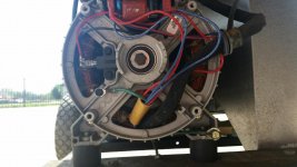
I took the generator head cover off and this is what I see.


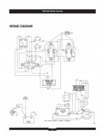
So I pulled out the old wire Diagram and I think this generator is bonded at the 2nd
120v outlet. (see page 3) (sorry having trouble converting PDF to JEG
 

Attachments

  • Generator windings.jpg
    Generator windings.jpg
    139.7 KB · Views: 109
Last edited:
To avoid these ads, REGISTER NOW!
OP
A

AP514

Well-known member
Joined
Jan 23, 2014
Messages
768
Location
Pearland, Tx
Sorry guys got side tracked after my partial post. Converted the Wire Digram from PDF to JPEG.
POWERBOSS 7000/12000
Wire Diagram-(2nd Below)..I think just Disconnecting the ground at the 120v outlet (marked) will UNBOND Generator.
Is This Correct ??? IF so I plan on adding a Switch like the mod in this thread.

https://www.garagejournal.com/forum/showthread.php?t=466583
@NOLTZ Awesome Job.
 

Attachments

  • Generator-Diagram -JPEG.jpg
    Generator-Diagram -JPEG.jpg
    46.4 KB · Views: 48
  • Generator Unbonded-Diagram.jpg
    Generator Unbonded-Diagram.jpg
    63.9 KB · Views: 39
Last edited:
OP
A

AP514

Well-known member
Joined
Jan 23, 2014
Messages
768
Location
Pearland, Tx
Yes, I think so..P1 -5 is the Ground on that Plug (marked) that ground goes thru up and around to the RED X. The Ground then connects to the Neutral on the plug (Bonding)
 
To avoid these ads, REGISTER NOW!

Noltz

Well-known member
Joined
Mar 10, 2020
Messages
377
Location
Ontario, Canada
Thanks AP. Yes I believe you're right. P2 red X's should be removed. If it's convenient & there's room on your panel that'd be an easy spot to add a switch.
 
OP
A

AP514

Well-known member
Joined
Jan 23, 2014
Messages
768
Location
Pearland, Tx
Yup had some room. So went ahead and installed switch. Still need to label Switch.
A few Pics of the Switch and also a shot of my oil Drian Mod.
 

Attachments

  • Unbond Switch.jpg
    Unbond Switch.jpg
    102.7 KB · Views: 57
  • Unbond Switch-Oil Drain.jpg
    Unbond Switch-Oil Drain.jpg
    127 KB · Views: 59
  • Generator Unbonded-Diagram.jpg
    Generator Unbonded-Diagram.jpg
    64.9 KB · Views: 54
  • Generator Switch Placard.jpeg
    Generator Switch Placard.jpeg
    459.7 KB · Views: 7
Last edited:
OP
A

AP514

Well-known member
Joined
Jan 23, 2014
Messages
768
Location
Pearland, Tx
Now I have a Question about the Switch I installed.
The Switch is rated at 120v/20A-240v/10A.
The ground wire to the outlet and the jumper I disconnected in the Diagram was 12awg.
I used 12Awg stranded THHN wire to and from the switch.

I should be ok ??
 

Noltz

Well-known member
Joined
Mar 10, 2020
Messages
377
Location
Ontario, Canada
Now I have a Question about the Switch I installed.
The Switch is rated at 120v/20A-240v/10A.
The ground wire to the outlet and the jumper I disconnected in the Diagram was 12awg.
I used 12Awg stranded THHN wire to and from the switch.

I should be ok ??

Gauge is good. That's the same size switch I've seen used on generators elsewhere, I've used it myself. It's important to remember the switch isn't carrying current in normal circumstances and is rated at 10A to make and break the circuit, at a given voltage. In other words the switch opens sufficiently to stop 10A from flowing at 240v. But we're not ever going to make or break a live circuit with the switch so it's my opinion the switch is sufficient to hold for that split second needed to trip the breaker.
 
OP
A

AP514

Well-known member
Joined
Jan 23, 2014
Messages
768
Location
Pearland, Tx
Thanks for the Reply........Noltz.

I figured it was good but wanted some feedback.
Besides I plan on using the Generator hooked up to House Manaual Transfer 95% of the time. (This will have that switch out of the loop and being used)
The other 5% will be just using the 120 outlets and that switch is rated at 20A on 120v .
 
To avoid these ads, REGISTER NOW!
Top Bottom