To avoid these ads, REGISTER NOW!

Upgrading my HF Bead Roller

astroracer

Well-known member
Joined
Jun 22, 2005
Messages
3,001
Location
Mid_Michigan
I've had a Harbor Freight bead roller for quite a while. It has been a workhorse in my shop for panel fab and now I think it is time to give it some love.
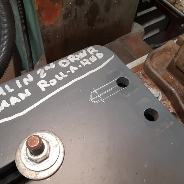
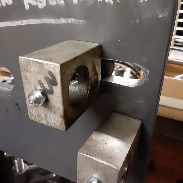
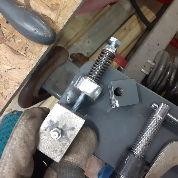
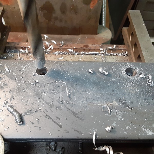
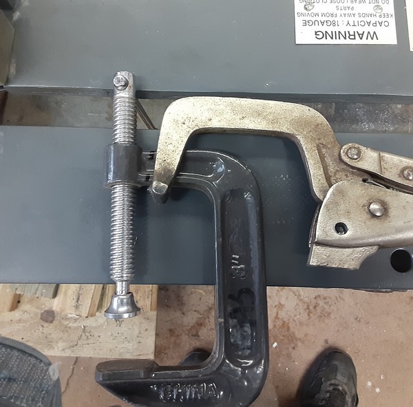
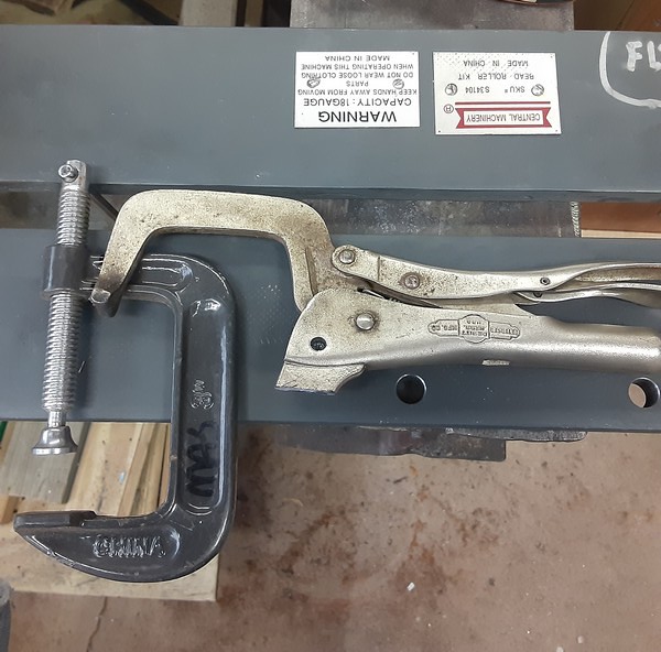
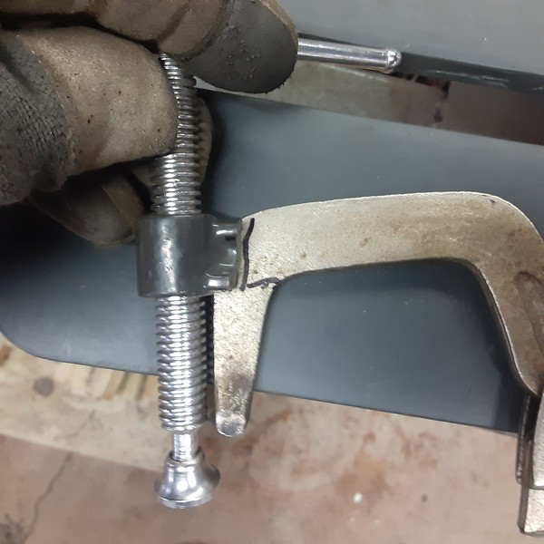
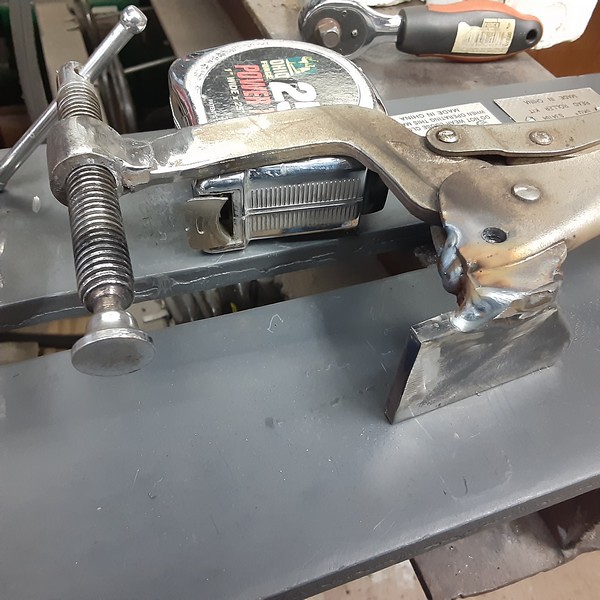
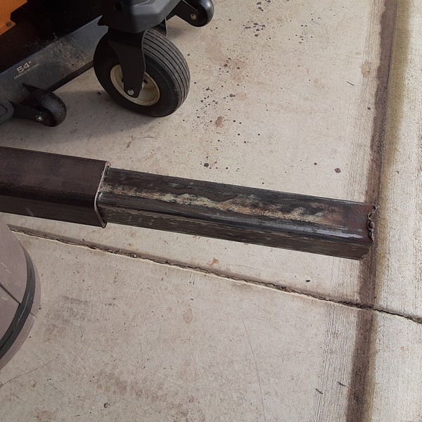
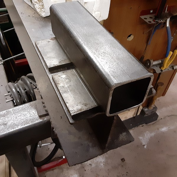
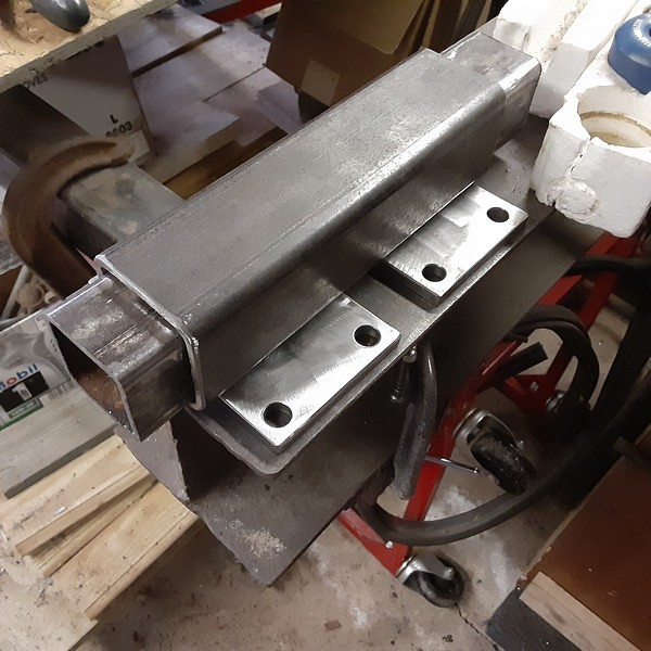
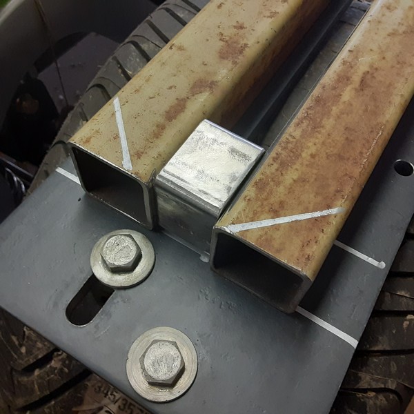
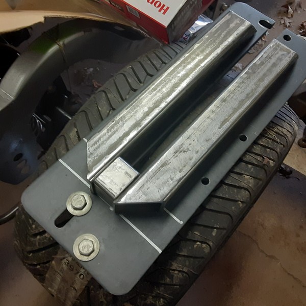
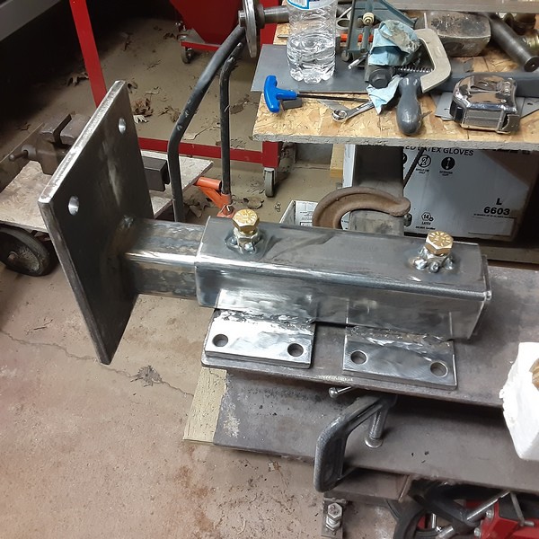
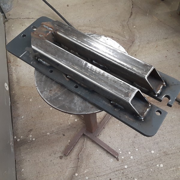
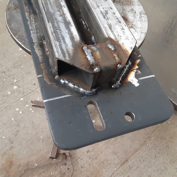
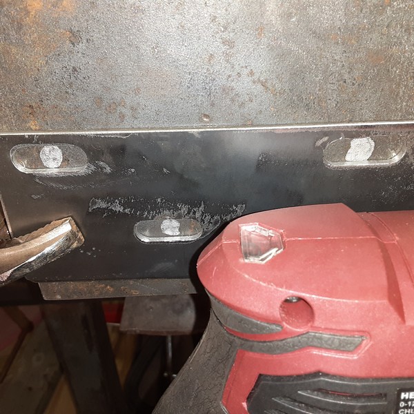
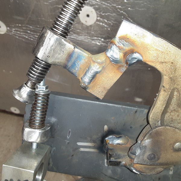
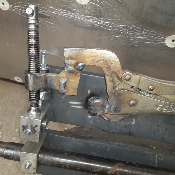
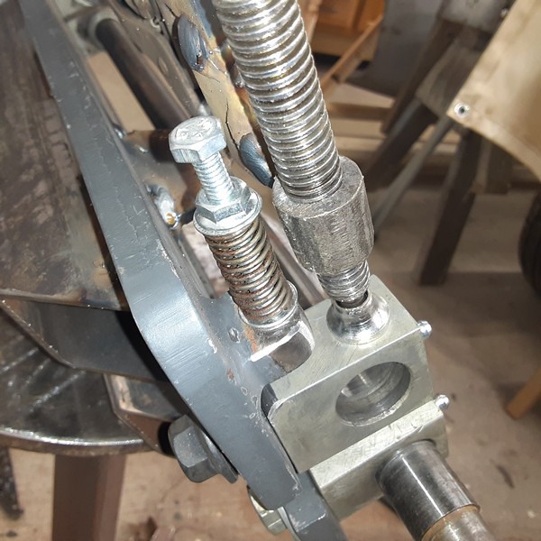
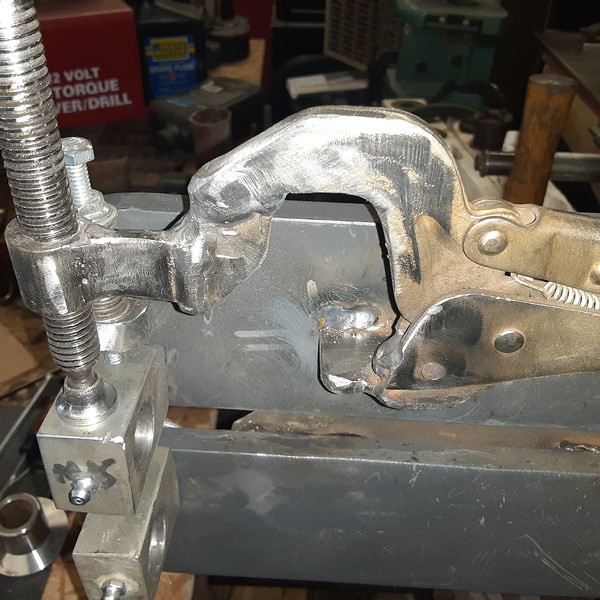
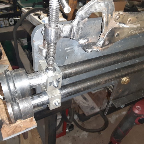
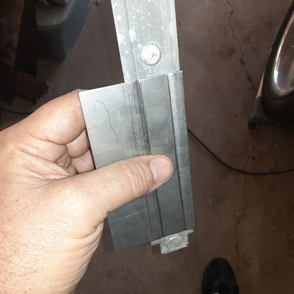
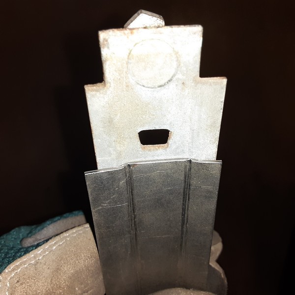
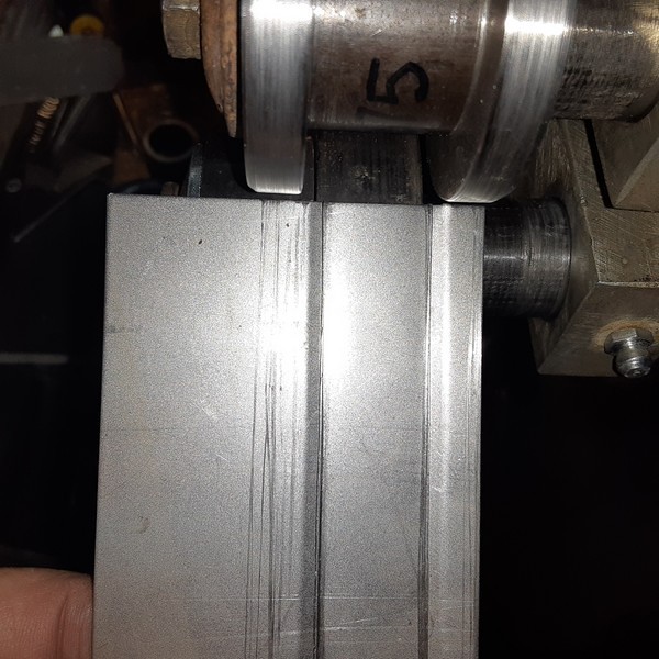
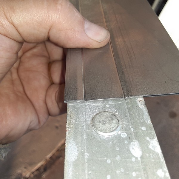
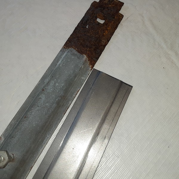
I am doing the tubing reinforcement to the base plate, adding a return spring for the upper die and reworking a Vise-Grip clamp to replace the tightening screw. I am also building a receiver tube so it can be plugged into my chassis jig or the tool stand.
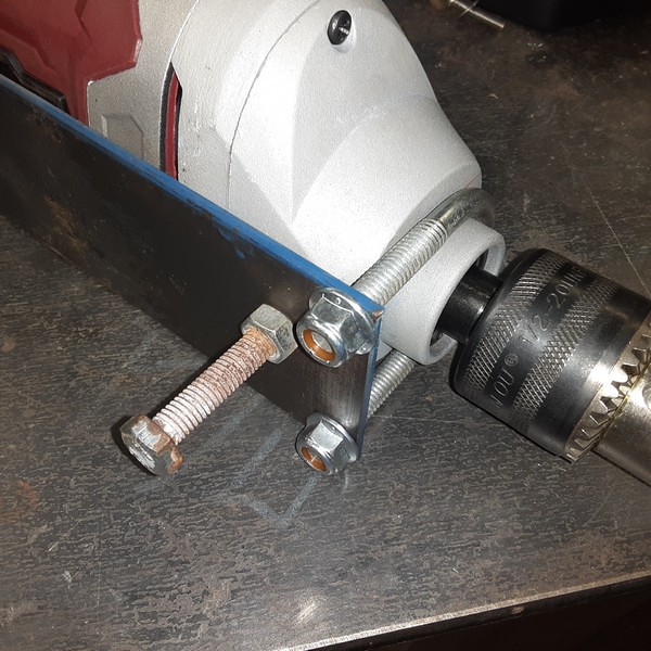
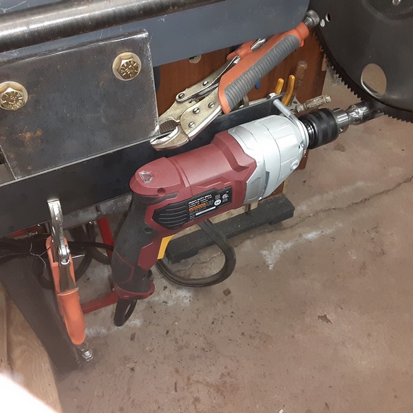
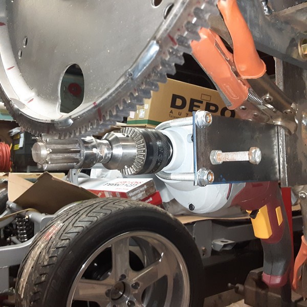
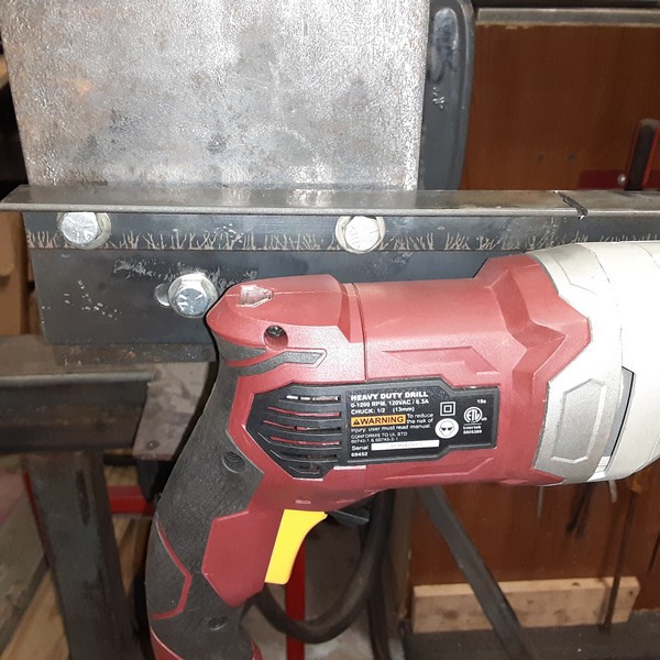
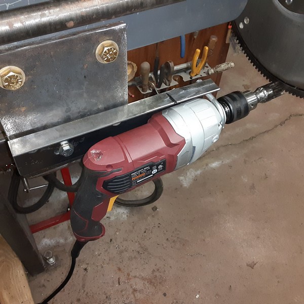
I will also be adding a HF 1/2" drive drill motor to drive it thru an automotive flexplate and pinion gear. I have had a pretty good time getting this off the ground this week. Still have a bit to do but I got most of the welding done today to get the roller mounted so I can put it back together to work out the drill driver mounting.
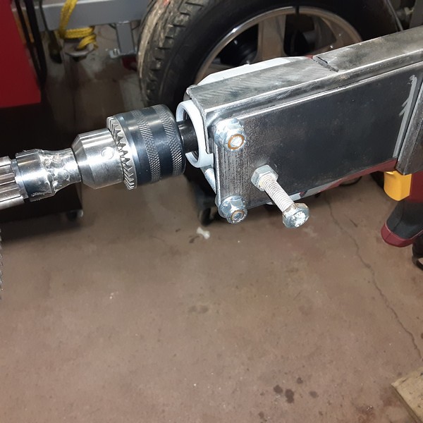
These first few pics are of the adapters I had to make for the flexplate and pinion gear.
2v2HyvT7qx9EDKg.jpg

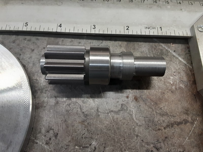
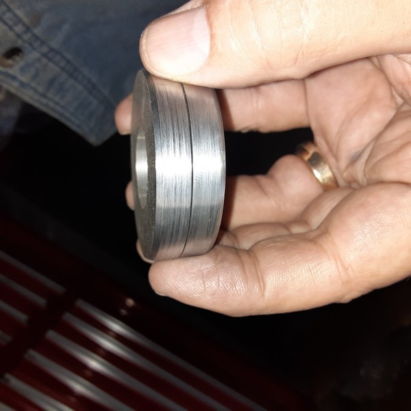
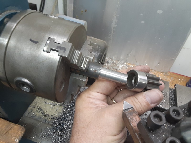
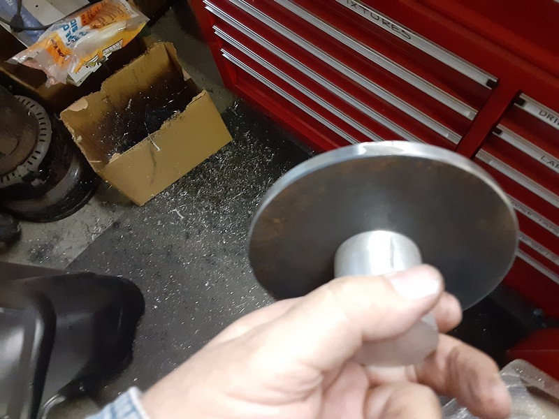
Starting the pinion gear adapter. You can see the ID's of the gear in this pic. I am turning the smaller one here. I will turn a shoulder to pilot down into the bigger ID then turn the adapter around in the chuck to spin it down to about a 1/2" to fit the drill chuck.
2v2HyvTWjx9EDKg.jpg

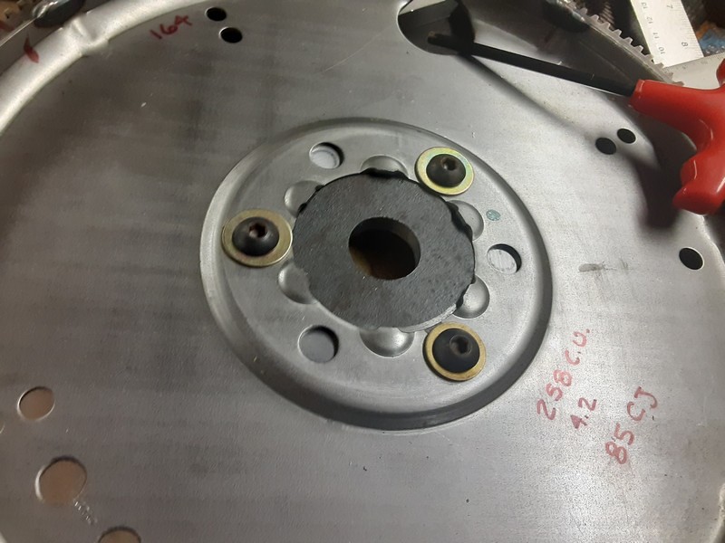
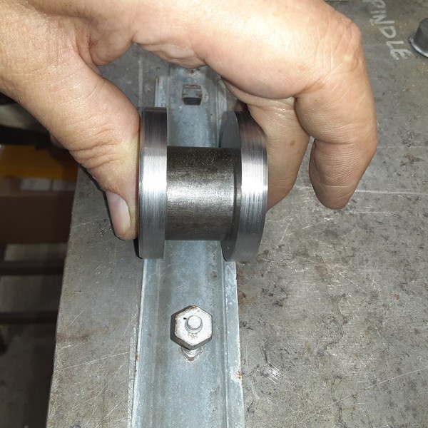
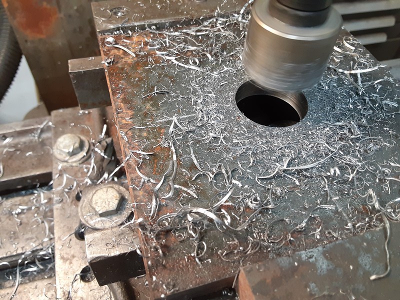
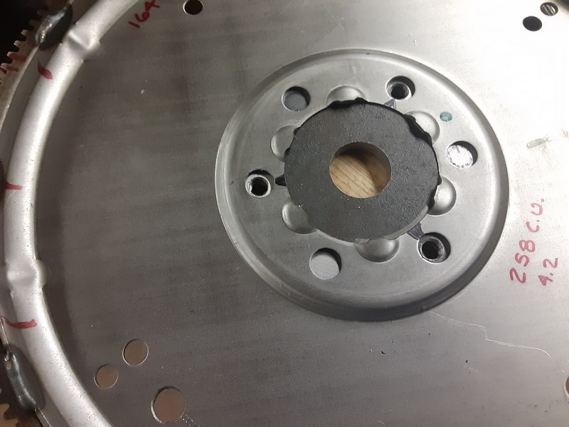
I made the flexplate adapter out of a piece of 3/8"s inch plate and a keyed bushing. The bushing will have to be bored out to fit the roller shaft and then welded to a plate. That I chunked out with the bandsaw and a cutoff disc then mounted it in the mill and cut the center hole with an 1 1/4" Rota-Broach. perfectly round hole and it fit the step on the bushing like a glove.
2v2HyvAuUx9EDKg.jpg

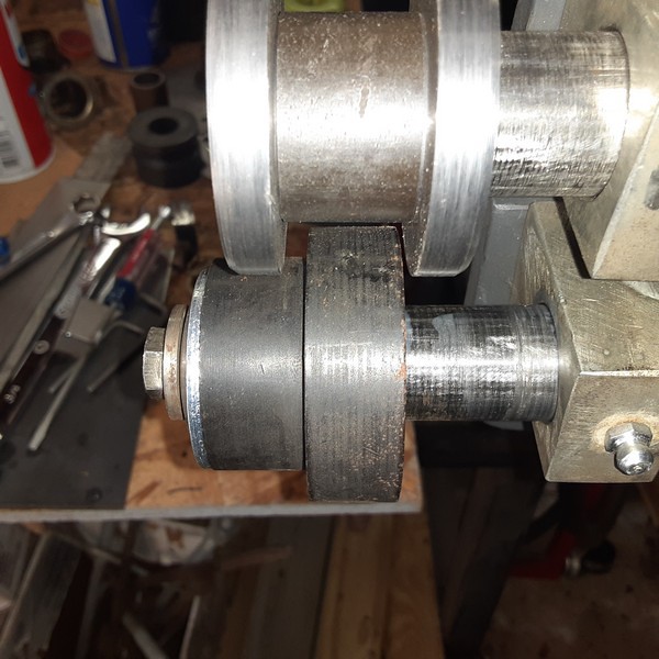
That hole was then used to bolt on a mandrel so I could chuck the plate up into the Lathe.
2v2HyvBYMx9EDKg.jpg

I spun it round and then faced the plate about a 1/16th of an inch and brought that diameter down to a snug fit in the pilot hole in the flexplate.
2v2HyvBEzx9EDKg.jpg

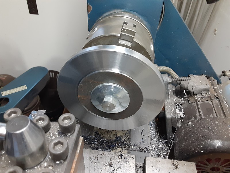
This locates the flexplate nicely so it should run fairly true to the shaft after it is all put together. Drilling and tapping a few holes gets this bolted up. :)
2v2Hyvqo2x9EDKg.jpg

I'll add more pics later, it's getting late and I am ready for bed...
Mark
 
To avoid these ads, REGISTER NOW!

metlmunchr

Well-known member
Joined
Sep 10, 2011
Messages
1,278
Re: Upgrading my HF Bear Roller

Good thread. Suggest you get one of the mods to edit the title. Probably a lot more people interested in a bead roller than a bear roller :)
 
OP
A

astroracer

Well-known member
Joined
Jun 22, 2005
Messages
3,001
Location
Mid_Michigan
Re: Upgrading my HF Bear Roller

Nice!

The pinion gear I assume you took from a starter?

Yes, a buddy gave me the flexplate. It fits an '85CJ straight six so I ordered a Bendix for it and cut it apart.
2v2HyvqB9x9EDKg.jpg

Here are some pics as I modified the backing plate. I slotted the top rear bolt hole to allow the shaft to move for upper die adjustment,
2v2Hy7Quzx9EDKg.jpg

2v2Hy7ZP5x9EDKg.jpg

2v2Hy7ZGMx9EDKg.jpg

drilled a clearance hole for the 1/4" die return bolt and trimmed off that block to make room for the modified vice grip for die clamping.
2v2HyTALUx9EDKg.jpg

Two holes were also drilled for 1/2" bolts that will attach the bead roller to my receiver adapter.
2v2Hy7QQ8x9EDKg.jpg


I cut up two perfectly good clamps to make the upper die clamp...
2v2HyTBp2x9EDKg.jpg

This will make setting the die so much easier and faster it will be worth it. I did some eyeball engineering, cutting the lower jaw off, leaving some material to weld on a spacer block.
2v2HyTBc3x9EDKg.jpg

I trimmed off the upper jaw, removing the drop leg so the clamp lug can weld straight on.
2v2HyTAyvx9EDKg.jpg

I should have left about an inch of the drop in place. That would have spaced the clamp up a bit more in relation to the die shaft.
THIS would have been a good spot...
2v2HyTBp2x9EDKg.jpg

Hind sight, I guess. This will work but I will need to tip the clamp a bit to get room above the shaft.
New clamp, ready to weld to the backing plate.
2v2HyTB9Mx9EDKg.jpg

Thanks for watching, I'll post more later. :)
If you have any questions holler!
Mark
 
OP
A

astroracer

Well-known member
Joined
Jun 22, 2005
Messages
3,001
Location
Mid_Michigan
Re: Upgrading my HF Bear Roller

I have a bunch of 2" sq. x 1/8" wall tubing I bought years ago that was reclaimed from pallet racks. I will use this to make the mount for the bead roller and it will slip into a piece of 2 1/2 x 3/16's wall tube that will act as the receiver. I drilled some holes in a couple of plates and welded those to the 2 1/2" tube. I can then bolt or clamp this to my jig tables or tool stand.
2v2Hys7e5x9EDKg.jpg


2v2Hys7cdx9EDKg.jpg


2v2HysRZGx9EDKg.jpg

I used some of that reclaimed tube to reinforce the back plate as well. This will be plenty stout and will change the whole way this roller feels when doing a bead.
2v2HyssMrx9EDKg.jpg

2v2HysPEjx9EDKg.jpg

2v2HyT6QEx9EDKg.jpg

2v2HyT6Wax9EDKg.jpg

2v2HyTB82x9EDKg.jpg
 
OP
A

astroracer

Well-known member
Joined
Jun 22, 2005
Messages
3,001
Location
Mid_Michigan
Re: Upgrading my HF Bear Roller

I worked out the mounts for the drill motor as well. Just a piece of 1/8 plate drilled for a 1 3/4" U-bolt that will trap the front of the drill and I added a hole that will bolt to the T-Handle mount on the side. This should hold the drill pretty steady with no worries of it moving during operation.
2v2HyqLrNx9EDKg.jpg

This plate will bolt to the mount for the bead roller. Here it is clamped in place so I can do a trial run with the motor to see how it works. :)
2v2Hyqg3yx9EDKg.jpg

The drill motor will work just fine. Getting the mounting plate drilled with a few slots and drilling and tapping the receiver mount will be next on the to do list. The drill plate is going to need to be slotted a bit so the pinion gear can be adjusted for quiet running.
2v2Hyqg2dx9EDKg.jpg

I also started doing some set-up work with the gears, the adjustable upper rear block and getting the quick clamp positioned. I needed another spacer to set the top gear to the rear block. I pulled a chunk of 1 1/4" x 5/16 wall tube out of the scrap bin, cut off a short piece and bored it out to fit the shafts and cut it down to 1/2" long. Drilling and tapping for an M8 x 1.25 set screw (same as all the other Chinezeum set screws... )
https://media.fotki.com/2v2HyqgEqx9EDKg.jpg[/img
Setting up the quick clamp I ended up trimming a bit off the spacer block to center it to the upper shaft better. I will get this welded on later after I get the drill motor mounts finalized.
[img]https://media.fotki.com/2v2Hyqgeyx9EDKg.jpg
This is getting close. :)
Mark
 
OP
A

astroracer

Well-known member
Joined
Jun 22, 2005
Messages
3,001
Location
Mid_Michigan
Re: Upgrading my HF Bear Roller

Nice work

Thanks!
I slotted the drill motor plate today,
2v2H5oSB2x9EDKg.jpg

transferred hole locations to the mounting plate and drilled and tapped those for 3/8-16 bolts.
2v2H5oST9x9EDKg.jpg

There is "just" enough slop in the mounting holes to allow me to set the pinion depth to the flexplate for a very quiet gear mesh.
2v2H5oSi2x9EDKg.jpg

I also added a piece of angle to the motor plate to control any "rollback" the drill was seeing during startup.
2v2H5oS4vx9EDKg.jpg

It wasn't much but it was still there so this piece stiffened it up nicely so now there is no movement of the drill when I hit the gas.
This is almost ready to use! A little bit of welding (attaching the quick clamp)
and some cleanup grinding and i should be running beads tomorrow.
Thanks for watching!
Mark
 

Algoma56

Well-known member
Joined
Apr 16, 2007
Messages
67
Location
Sault Ste. Marie, ON
Re: Upgrading my HF Bear Roller

Perfect timing for your post. My sons gave me a similar bead roller for Christmas. I knew from past research, comments and posts on various forums, that I should stiffen it up.
I have some 1-1/2 square tubing chunks to use up, so that will be first.
 
OP
A

astroracer

Well-known member
Joined
Jun 22, 2005
Messages
3,001
Location
Mid_Michigan
Re: Upgrading my HF Bear Roller

Haven't had much time to get out to the shop. I got the drive brackets all wrapped the other day and, after looking at my 1st attempt for the quick clamp decided to redo that a bit to shorten up the reach. I used the lower jaw I cut off to drop the clamp head closer to the bearing block. A little cutting, a little welding and this is done and will work nicely. I will clean it up a bit with the grinder and round off some of those straight corners.
Clamp open.
2v2H5kgc2x9EDKg.jpg

Closed up
2v2H5kg68x9EDKg.jpg

Adding the "C-Clamp" to the Vice Grip will let me sneak up on the depth setting when rolling heavier material or tipping a flange PLUS it will leave that setting alone when I open the vice grips to release the material. That will be handy.
2v2H5kg4Mx9EDKg.jpg

I haven't had a chance to use it yet but I am expecting good things.:)
Mark
 

NUTTSGT

Super Moderator
Staff member
Joined
Sep 14, 2009
Messages
50,879
Location
Northern Central Ohio
Title fixed as requested.


One question, are you locking that trigger on the drill when you're using it ? If you have an issue like getting a finger or glove caught in it, how do you shut it off ? I'd suggest getting a foot pedal for the "throttle."
 
OP
A

astroracer

Well-known member
Joined
Jun 22, 2005
Messages
3,001
Location
Mid_Michigan
I got the upgraded BEAD roller cleaned up and operational today. Did some clean up work on the quick clamp and touched up the welds for the braces on the back side. After I get some use out of it I will probably pull this all apart and take to a powder coating shop for blasting and coating. We'll see how well it works before I pull the trigger on that.
2v2H5ydS4x9EDKg.jpg


Eric, I am locking the trigger on the drill right now and running it with a variable speed foot pedal.
2v2H5ydsmx9EDKg.jpg

It works right now for proof of concept but I have a reversing foot pedal coming from Amazon and I will be rewiring the drill to use that pedal. I will also be adding a router speed controller to the mix so I can just stomp on the pedal to make it go and rely on the speed controller to keep the RPM's constant.
I ran a few beads on a small piece of scrap 20ga. The bead roller works great. No more twist when clamping the metal in place, the drill has no problem running the bead and the new quick clamp works very well.
2v2H5yd7Dx9EDKg.jpg

I am happy with the way this turned out, now to get the drill motor set up to work better with a new pedal and remote speed control.
Mark
 
To avoid these ads, REGISTER NOW!

metlmunchr

Well-known member
Joined
Sep 10, 2011
Messages
1,278
Nice job and no doubt 10X more useful than the wobbly original.

If you've ever watched Lazze's bead rolling videos on Youtube, the upper shaft on his bead roller is adjustable in and out. A handy thing for some operations, but not really something that could be added to the HF roller without a bunch of work.

For my own HF, I picked up some spacers for horizontal machining arbors to use to space the upper roll out from the standard position when useful.

https://www.travers.com/arbor-spacers/p/93000/

The ones with 7/8" hole are the ones to get. I picked up a ten pack of the 1/16" and a ten pack of the 1/32" for around $20 total. The HF shafts are 25mm and the diameter steps down to 22mm where the rolls sit. 7/8" is 22.2 mm so they slip right on and bottom out against the 25mm step. They're hardened and ground and dead accurate to size. I keep a 1/16 on both upper and lower shafts all the time to protect the shaft step and the inboard end of the roll bores from chewing into each other over time since the step is small and gets a lot of force if using the end retaining screws rather than just the setscrews.

Just figured this was worth mentioning for the OP or anyone else who happens to own one of these marvels of precision machining :D
 

rsanter

Well-known member
Joined
Dec 22, 2007
Messages
18,493
Location
visalia ca
Bead rolling is fun
I upgraded from the old HF unit long ago

This is what I have now. It is based on the lazzie design
 

Attachments

  • IMG_0196.jpg
    IMG_0196.jpg
    87.8 KB · Views: 139
OP
A

astroracer

Well-known member
Joined
Jun 22, 2005
Messages
3,001
Location
Mid_Michigan
Nice job and no doubt 10X more useful than the wobbly original.

If you've ever watched Lazze's bead rolling videos on Youtube, the upper shaft on his bead roller is adjustable in and out. A handy thing for some operations, but not really something that could be added to the HF roller without a bunch of work.

Go back to post #5, :) I milled a slot for the rear upper block to move in, that is all that needs to be done to make the upper shaft adjustable. :)
Mark
 
OP
A

astroracer

Well-known member
Joined
Jun 22, 2005
Messages
3,001
Location
Mid_Michigan
The reason for all of the upgrades. In the process of pulling my '56 wagon apart for rust repair and repainting I removed the C pillar covers. These are held on with a metal plate that bolts thru the C pillar. The lower 3rd of one is badly rusted.
2v2HNG1KEx9EDKg.jpg

The rusted portion.
2v2HNG1bJx9EDKg.jpg

I was going to just replace this portion but, now that The bead roller is capable of making this shape, I will just make a whole new plate.

I made a couple of washers out of 1/4" plate to make the flange portion. These needed a sharp edge to make that corner of the flange. I put a 45 on the other edge to make them reversible for other uses.
2v2HNG1wNx9EDKg.jpg

A spacer was made out of DOM 1 1/4 tube to set the width. I ended up making two of these as the first one was a bit too narrow.
2v2HNG1R5x9EDKg.jpg

Set up in the roller. Being able to adjust the spacing with the top bar was a big plus! I used one of the standard forming dies in the lower position to make the "bump up". It was a perfect fit to the inside of the original plate.
2v2HNG1sNx9EDKg.jpg

2v2HNd8Dqx9EDKg.jpg


I ended up running a couple of test pieces. The first one was a bit narrow (not that it really matters) and another with the wider spacer.
2v2HNd8S5x9EDKg.jpg

The pieces turn out very nice after a few trips thru the dies. The initial forming takes 6 or 7 trips, sneaking up on the full depth.
2v2HNd8AGx9EDKg.jpg

As you can see the initial forming puts a bit of a tip into the flanges AND a bit of a curve into the length of the piece.
2v2HNd8VNx9EDKg.jpg

To flatten the flanges out and remove the curve I turned the piece over and ran it thru the dies "upside down". I backed off the pressure and kept increasing it until the flanges came out totally flat. Only took 3 or 4 trips to get it flat.:)
2v2HNd8Tyx9EDKg.jpg


This will work great and gets me a piece that is not reproduced for these cars...
2v2HNd8Prx9EDKg.jpg

2v2HNd8gqx9EDKg.jpg

Mark
 

rsanter

Well-known member
Joined
Dec 22, 2007
Messages
18,493
Location
visalia ca
I have thought about that... I'll haven't posted this on the Tri-Five Forum yet, we'll see what reactions I get when I do... :)

Even if you don't get the most positive reaction, I would at least make a few and put them on eBay.
I'm betting you will sell a few and the investment is low

Besides, playing with a bead roller is fun
 

slodat

ALLIANCE MEMBER
Joined
Feb 6, 2010
Messages
3,679
Location
Central-ish, WA
Great work! Even cooler is you made the machine, then the tooling and finally the part. That’s good stuff! Thanks for posting!
 
To avoid these ads, REGISTER NOW!
Top Bottom