To avoid these ads, REGISTER NOW!

Using a momentary switch to deliver constant power?

Jliddle

Well-known member
Joined
Sep 21, 2016
Messages
49
Hi all, I am doing some winter mods on my Street Glide. One of which is rear air ride. I have a kit that includes a "ride height repeater" basically two pieces of aluminum that slide together and when the rear bags reach a certain length of extension, they bump a small disconnect, cutting power to the compressor. This is supposed to give you the same exact ride height every time.

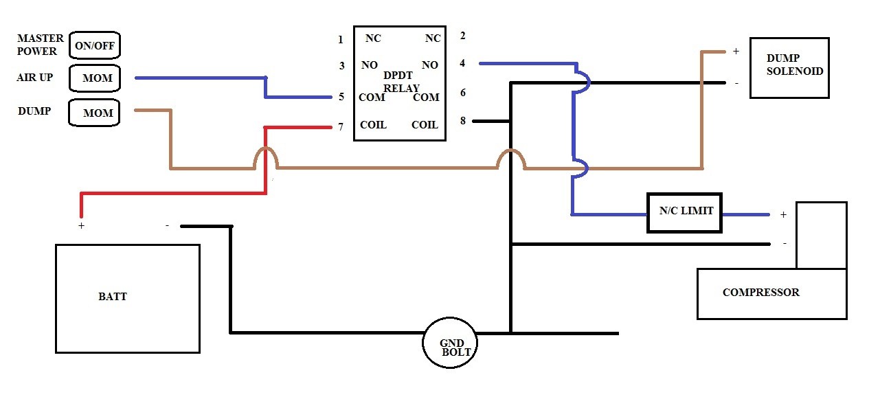
My idea is to use a factory momentary switch on the dash, press it once ( do not hold down ), this powers the compressor up and starts pumping the bags. Then the bags reach the determined ride height and the disconnect cuts all power. There is also a master power on/off push type switch, as well as a momentary dump valve switch.

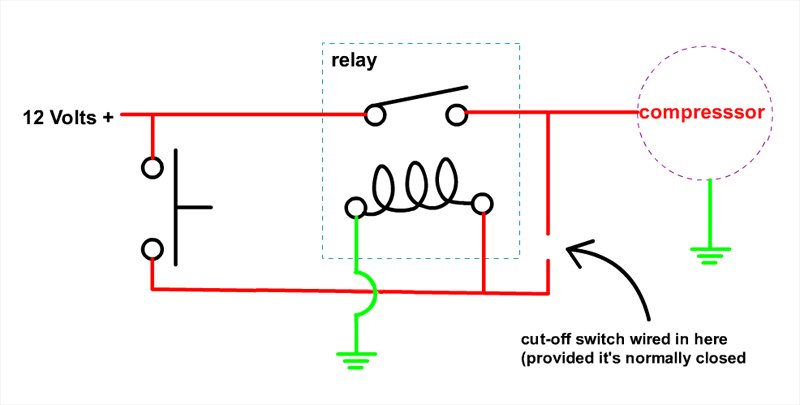
My question is how can a momentary switch be used in this application to deliver constant power until the disconnect cuts power. Mind you the compressor is very small and would only run for a minute or two max.
 
To avoid these ads, REGISTER NOW!

Stuart in MN

Well-known member
Joined
Sep 8, 2005
Messages
23,112
Location
Minneapolis
Use the momentary switch to operate a double pole relay. One set of contacts on the relay will latch the power on to the relay, the other set of contacts will operate the air compressor.

I drew up a similar circuit a few years ago and posted it here: http://www.garagejournal.com/forum/showthread.php?p=2098832&highlight=latch#post2098832 This one was for 120vac, but the same thing will work with a 12 volt relay on a 12 volt system.
 

Stuart in MN

Well-known member
Joined
Sep 8, 2005
Messages
23,112
Location
Minneapolis
The relay is rated for 30 amps, I'll guess that's probably adequate but it depends on how much current your compressor draws.

I'm a little confused by the description in the ad - the title says it's a double pole double throw relay (DPDT) but the smaller text below says single pole (SPDT). Make sure you get a double pole relay. A regular automotive relay should be okay and should be available at any local auto parts store.
 

matt_i

Well-known member
Joined
Mar 14, 2008
Messages
10,727
Location
SE Michigan
The basic circuit is this "seal" circuit.

3_wire_control_01.jpg


In your case the momentary pushbutton is same as "start", the limit switch with a normally closed contact would be same as "stop", the circle labelled "40" is the relay coil and the -40- contact is a normally open contact on the relay.

More or less, the start pushbutton, depressed for an instant, energizes the coil of CR40 and this closes the ][-40- contact, all happening at the speed of electrons in copper wire. By the time the pushbutton is released the ][-40- contact is completing the circuit left-to-right instead of the pushbutton. This will maintain until the ladder power is dropped or the "stop pushbutton" or in your case the limit switch, changes states.

The parallel sides of the "ladder" are +12vdc on the left and -GND on the right.
 
Last edited:

Mickey O

Well-known member
Joined
Oct 25, 2009
Messages
6,153
Location
Chicago, IL
Here is a simplified version but with out knowing how its actually wired and if the limit switch (disconnect) is on the positive and normally closed. It can be done simply but we would have to see the wiring diagram for the system.

mcy-sw.jpg
 

Attachments

  • mcy-sw.jpg
    mcy-sw.jpg
    30.7 KB · Views: 11

wyliesdiesels

Well-known member
Joined
Aug 14, 2012
Messages
20,013
Location
Modesto, CA
Here is a simplified version but with out knowing how its actually wired and if the limit switch (disconnect) is on the positive and normally closed. It can be done simply but we would have to see the wiring diagram for the system.

mcy-sw.jpg

Thats missing the "seal" contact which holds the coil circuit closed after the momentary start button is opened/let go of.
 

Mickey O

Well-known member
Joined
Oct 25, 2009
Messages
6,153
Location
Chicago, IL
No, it's not missing anything, connect where it's open for the limit switch (black arrow) and it latches.
 
OP
J

Jliddle

Well-known member
Joined
Sep 21, 2016
Messages
49
Also as a "master" power on/off type switch, would it be ok to use the switch in the 12v supply for the DPDT relay for the momentary switch?

That way when the "master" switch is on, the DPDT receives 12v. However when the switch is off, it doesnt.

This is my thoughts on a kill switch that way if the bags were to develop any leak while riding (causing the limit switch to once again become a closed circuit) the compessor wouldnt stay running to try to keep up. With the motor running its quite hard to hear a 98c Viair compressor.
 

Mickey O

Well-known member
Joined
Oct 25, 2009
Messages
6,153
Location
Chicago, IL
Hey guys,

Here is the wiring diagram for the "repeater" which limits the extension of the shocks.
https://jnrdesigned.com/wp-content/uploads/2016/10/RHR-wiring-diagram.png

And heres the diagram for the compressor itself.
https://jnrdesigned.com/wp-content/uploads/2016/10/Base-rear-air-wiring-diagram.png

I looked at your two diagrams and it looks like they are using a solenoid for the "dump valve" and maybe for the compressor to a tank? Not sure. And I'm not sure what the purpose of the "bypass switch" is. I'm sure you can accomplish what you want to do but you'd have to lay it out for us to give you any advice. Meaning you'd have to tell us what all the components are; solenoids, switches, limits, pressure switches, etc. and what their function is, ie., is the high limit a normally open or closed switch (if it is a switch), etc. And then how you want it to function. You may well want to scrap the way the manufacturer shows and go your own route.
 
OP
J

Jliddle

Well-known member
Joined
Sep 21, 2016
Messages
49
So here's a sketch with what I have. The limit switch is open when there is no air in the bags, when the rear is aired up, the switch closes at a preset height. This shuts the compressor down.

Once again there's a on/off switch I want to use as a "master" power. That way it kills power to the compressor so the bike doesn't air up unintentionally while going down the road or sitting. JUST incase the air bags were to ever leak. The two momentary switches are to kick the compressor on using the dpdt relay as well as operate the solenoid to "dump" the air from the bags. The idea is to click the master power switch on, press the air up momentary once. The compressor will then start filling the bags until the limit switch closes and shuts it off.

 
OP
J

Jliddle

Well-known member
Joined
Sep 21, 2016
Messages
49
Here is said limit switch. http://www.mouser.com/Search/m_Prod...=sGAEpiMZZMumBvQ1hY/fBQj28shxzxZBhVXjojnz2GI=

The roller makes contact with a machined bracket at the desired point of ride height.

Just to test this I wired a single led to the battery with the limit switch in the positive wire. When the roller makes contact with the bracket, the light turns off. This would make it a normally closed type switch?
 
Last edited:
To avoid these ads, REGISTER NOW!
OP
J

Jliddle

Well-known member
Joined
Sep 21, 2016
Messages
49
Heres what I have as of tonight. I still havent came up with a good idea for a master power switch to the whole system. The switches Im using are OEM Harley accessory switches which are plug and play. There is a connector at the dash then it routes below the seat. So with some trial and error and a few wiring diagrams I can determine the pinout of the connectors and route them accordingly to my air ride system.


Any help is greatly appreciated because I am no wizard when it comes to anything beyond simple automotive wiring like lights or fuel pumps.
 

AntonLargiader

Well-known member
Joined
Nov 20, 2016
Messages
1,372
Location
Charlottesville, VA
You need to do the self-latching part, which means the power between the limit switch and the compressor is what holds the relay on. When the limit switch kills power to that section, the relay drops out. I'll call this the LS+ wire.

Also you need to show the power to the controls, just for completeness' sake.

For instance: B+ to the left side of the master. Green from the right side of the master to the input of the two momentaries. For this purpose, put the dump wire at the top so it doesn't have to cross anything else. Also run B+ to a relay common and from the corresponding NO to the limit switch. Then your momentary 'on' and the LS+ wire will both feed the coil+. When you press the button, the relay triggers, limit switch allows power to the compressor and maintains power back to the coil until it drops out.

The only weakness I see in what I've proposed is that the power switch won't kill the system if the LS goes bad; you may need a second relay for that. But draw up what I've said so far. Also, you can get rid of the black wire in the diagram and just show grounds at all of the ground points. Cleans things up a bit; we're really just interested in the switched positives here.
 

cgrutt

Well-known member
Joined
Mar 4, 2016
Messages
8,270
I think this is what you need to do. Note that I'm assuming the "dump" solenoid switch can handle current and only needs to operate when switch is depressed. You may need to run it through another relay if this is not the case.

31798909553_ea3676bee4_c.jpg
 

cgrutt

Well-known member
Joined
Mar 4, 2016
Messages
8,270
This is the switch kit. http://mstore.harley-davidson.com/store/auxiliary-power-switch-kit---fairing-mount

And instructions say that the switches without a relay are for 2amps and below. The solenoid is undoubtedly more than that so a relay will be a must for the solenoid as well as the master power.

Then just add another relay.
- Power from Battery+ to dump switch and and relay pin #5
- output dump switch to relay pin#7
- relay pin #8 to ground
- relay pin #3 to solenoid +
- solenoid - to ground
 

AntonLargiader

Well-known member
Joined
Nov 20, 2016
Messages
1,372
Location
Charlottesville, VA
The thing I don't like about that last diagram is that at the instant you press the fill button, it's carrying the full load to the compressor. After that the relay takes over. I think the way I described it the button only triggered the relay. It's better to separate the functions: button controls relay, relay controls compressor. That way when one component fails you don't get some unintended consequence.
 

cgrutt

Well-known member
Joined
Mar 4, 2016
Messages
8,270
The thing I don't like about that last diagram is that at the instant you press the fill button, it's carrying the full load to the compressor. After that the relay takes over. I think the way I described it the button only triggered the relay. It's better to separate the functions: button controls relay, relay controls compressor. That way when one component fails you don't get some unintended consequence.

Pretty sure a magnetic starter is configured the same way and relay "delay" is nearly instantaneous. However, you might add a diode between pin 3 and the limit switch to isolate the current on start/stop (air/limit) switches to the coil if it helped you sleep better, lol...

Other option is to run limit switch on other side of relay, between pins #4 and #7. In this case you also need to run 12V+ (from output side of master on/off before run switch) to pin #6.
 
Last edited:

Trey T

Well-known member
Joined
Aug 3, 2011
Messages
3,749
Location
Houston, TX
Momentary to latched
input (-)
ouput (+)
momentconstant.gif

diode across the left relay is 1n4001. These things bring back so much memory ... used to be an alarm/RS installer back in HS and college.
 
OP
J

Jliddle

Well-known member
Joined
Sep 21, 2016
Messages
49
I tried to revise it this evening between classes.
 
Last edited:

AntonLargiader

Well-known member
Joined
Nov 20, 2016
Messages
1,372
Location
Charlottesville, VA
Looks good. You omitted B+ feeding the master, and 87 feeding the other two switches, but you know that. Also, the way it's wired you will get compressor when you push the button even if the limit switch is made, but I don't see that as a problem.
 
OP
J

Jliddle

Well-known member
Joined
Sep 21, 2016
Messages
49
Looks good. You omitted B+ feeding the master, and 87 feeding the other two switches, but you know that. Also, the way it's wired you will get compressor when you push the button even if the limit switch is made, but I don't see that as a problem.

I did omit those because the factory harness supplies power to those switches. Ill just use the signal from the master switch to trigger the power relay for the air ride system.

Thanks to everyone for the help. This is an odd request around here I know but Im very appreciative for all the help.
 

Trey T

Well-known member
Joined
Aug 3, 2011
Messages
3,749
Location
Houston, TX
Post some pictures of the result.

Btw, it's not an odd request at all. The practices are different but the principle of switchings are all the same.
 

arrowhead

Well-known member
Joined
Dec 11, 2008
Messages
681
Location
Stillwater, NY
OP
J

Jliddle

Well-known member
Joined
Sep 21, 2016
Messages
49
I didn't read through the thread in depth but saw "latching relay" mentioned a couple of times. I used a Waytech electronic latching relay that works off a momentary button and they are rated a 15 amps at 12v. Maybe that might help.

https://www.waytekwire.com/item/75533/InPower-VCM-01-Latching-Solid-State-Relay-/

https://www.waytekwire.com/item/75532/InPower-VCM-10-Dual-Input-Solid-State-Relay-/

Im going to try the diagram I have above in about two weeks when I get back around the bike. Waytek lists those latching relays at around $40/per! Hopefully this works before I come to that.
 
To avoid these ads, REGISTER NOW!
Top Bottom