To avoid these ads, REGISTER NOW!

VFD not working as planned

Joined
Mar 17, 2016
Messages
16
Location
SW Michigan
To start off, I know next to nothing about electrical. I bought a VFD to power my engine hone and it will only work with the wires ran straight to the 3 phase motor.

The up and down pneumatic movement doesn't work even with air connected. I'm not sure if the VFD is sending the power to it incorrectly or not. Also, the 110 pump I believe is supposed to run off one of the 3 phase legs. With everything hooked up it doesn't work.

I could wire everything separately with 3 cords but I'd rather not if I can just run the main power wire.

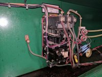
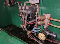
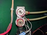
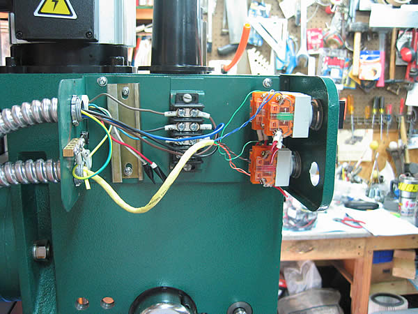
Any advice is appreciated, here are some pictures of the setup.
 

Attachments

  • IMG_20171002_192013.jpg
    IMG_20171002_192013.jpg
    145 KB · Views: 63
  • IMG_20171002_192019.jpg
    IMG_20171002_192019.jpg
    143.6 KB · Views: 66
  • IMG_20171002_192039.jpg
    IMG_20171002_192039.jpg
    144.1 KB · Views: 57
  • IMG_20171002_192025.jpg
    IMG_20171002_192025.jpg
    146.4 KB · Views: 54
  • IMG_20171002_192047.jpg
    IMG_20171002_192047.jpg
    123.2 KB · Views: 53
  • IMG_20171002_192210.jpg
    IMG_20171002_192210.jpg
    144 KB · Views: 45
To avoid these ads, REGISTER NOW!

LXCam

ALLIANCE MEMBER
Joined
Apr 23, 2013
Messages
19,180
Location
AZ
The VFD needs to go only to the motor. You'll need to identify which leads power up the control circuit. There has got to be more wiring then that, is there another control center? Also get a picture of the whole interior in one shot and a close up of the old magstarter. This will make it easier to identify where the control wires are tied into.

Maybe I should clarify. Take a picture straight at the mag starter and straight at the entire enclosure.

Also if you're lucky enough to have a schematic, that'd answer most every question.
 
Last edited:

mm08822

Well-known member
Joined
Jan 13, 2012
Messages
6,034
Location
NJ
What voltage was the machine wired for before you got it?

You mention a vfd but there is no pic of it. Where is it fed from? What is the purpose of the motor starter now that you have a vfd?

Where did the s.v.'s and pump get 110vac before you made changes? Any transformers inside with a 110v secondary?

The vfd should only be powering the motor and only the motor should be connected to that output.

The vfd is not going to source 110v.

Need More pics.... Motor nameplate, vfd nameplate, vfd wiring.....
 

larry_g

Well-known member
Joined
Apr 28, 2007
Messages
16,893
Location
oregon
Also if you're lucky enough to have a schematic, that'd answer most every question.

If you don't have the schematic, give us the machine brand and model number and we maybe can find in on the 'net.

You may have to bring 240vac + neutral into the machine and drive the controls from 120v. The controls start and stop the VFD which is connected to the motor only. Not for the "I know next to nothing about electrical" guys.

This thread sounds like one that we just went through with another guy here. Maybe some one can link to that one.

On edit , I found the one I was thinking of, https://www.garagejournal.com/forum/showthread.php?t=324800 It is for a press but the idea is similar. see post #9

lg
no neat sig line
 
Last edited:

BillK

Well-known member
Joined
Aug 24, 2006
Messages
9,358
Location
Beautiful Southern Maryland
cw,
You didnt mention what type of hone it is. Mine has one junction block where the 3 phase comes in and then everything else is split off from there. I am betting you have a problem with the controls. Do you have a manual ? Looks like maybe a Kwik Way from the color ?

I dont think the problem is the VFD. Was it working properly where it was before you bought it ?

Are you trying to use the VFD as a phase converter ? Not sure if it will work like that. Maybe someone else can chime in but I think what you need is a phase converter to feed three phase to the entire machine.
 
Last edited:

LXCam

ALLIANCE MEMBER
Joined
Apr 23, 2013
Messages
19,180
Location
AZ
Pretty sure what he did was wire the VFD in at the main junction box. But did you guys notice the holding circuit contacts had been bypassed on the starter? Not sure if he did that or that was previously done. Also the motors leads had been moved to the top of the starter, but I'm thinking he did that to bypass the starter. And I think the pneumatic solenoid are what controls up/down but that's a guess and I can't tell if they're 120 or 240v units. I would think there's a control transformer buried somewhere but it could have been 3ph 4w too. But there are control wires that run off to the right at the bottom and back of the panel, it looks like the nuetral is within that bundle, but not the incoming motor leads, the wires look too small. Guess we'll see what the OP comes back with for info.
 
Last edited:

larry_g

Well-known member
Joined
Apr 28, 2007
Messages
16,893
Location
oregon
cw,

Are you trying to use the VFD as a phase converter ? Not sure if it will work like that. Maybe someone else can chime in but I think what you need is a phase converter to feed three phase to the entire machine.

This is where a rotary phase converter works when a VFD doesn't. I have a large mill with 3 motors and other controls that works well on a rotary. Just make sure that if you are using a rotary that the controls are not fed with the generated leg.

lg
no neat sig line
 
To avoid these ads, REGISTER NOW!
OP
C
Joined
Mar 17, 2016
Messages
16
Location
SW Michigan
Ok I will have to get pictures tomorrow but the machine is a Peterson Powerstroke HC-1DP. The guy I bought it from ran it for me when I picked it up so I know it all worked before. From what I'm reading I'll have to get an actual phase converter and not the VFD if I want to run just the individual power cord.

The coolant pump was 110 already, I didn't change that. The pump is powered off of the blocks where the three phase comes in so my uncle said it was using one of the 3 phase "legs".

This link is the VFD I'm using. I know everyone says not to go with the Chinese brands but my uncle has had this same brand on his lathe for years with zero issues.

https://www.ebay.com/p/Huan-Yang-2-...10a-220v-Wholesale/895863308?iid=261939812616

Thanks for the help everyone
 

Matt Matt

Well-known member
Joined
May 11, 2017
Messages
523
Location
Ontario
All I see is a three phase contactor, Some control circuits, and A three phase 220 V hot wire coming in, Which looks like it is jumpered to single phase.

What manufacturer and model VFD did you get?
Did you get manufacture/sales/engineering support?

The 110 V pump, is it possible it is 220 single phase? Can you show us a picture of the motor tag? The motor tag it is right on top of the motor on the right side. If your uncle is right, they're pulling 110 using the ground line unless there's a transformer you're not showing us about. How did your uncle wire his lathe?

Edit, I see you made a post while I was typing. You should go and ask them on practical machinist forum. They are absolute specialists when it comes to HY VFD's in the transformer, phase converter, VFD subforum.
 
Last edited:

mm08822

Well-known member
Joined
Jan 13, 2012
Messages
6,034
Location
NJ
Pretty sure what he did was wire the VFD in at the main junction box. But did you guys notice the holding circuit contacts had been bypassed on the starter? Not sure if he did that or that was previously done. Also the motors leads had been moved to the top of the starter, but I'm thinking he did that to bypass the starter. And I think the pneumatic solenoid are what controls up/down but that's a guess and I can't tell if they're 120 or 240v units. I would think there's a control transformer buried somewhere but it could have been 3ph 4w too. But there are control wires that run off to the right at the bottom and back of the panel, it looks like the nuetral is within that bundle, but not the incoming motor leads, the wires look too small. Guess we'll see what the OP comes back with for info.

I still see T leads on the starter(black) and the 4-wire cord on starter line side looks like power to the starter.

OP confirmed that sv's are 240, but I'm wondering if tha 110v pump wasnt fed from one input phase and the ground! Lets hope there was a 4wire feed or xformer.
 

mm08822

Well-known member
Joined
Jan 13, 2012
Messages
6,034
Location
NJ
Ok I will have to get pictures tomorrow but the machine is a Peterson Powerstroke HC-1DP. The guy I bought it from ran it for me when I picked it up so I know it all worked before. From what I'm reading I'll have to get an actual phase converter and not the VFD if I want to run just the individual power cord.

The coolant pump was 110 already, I didn't change that. The pump is powered off of the blocks where the three phase comes in so my uncle said it was using one of the 3 phase "legs".

This link is the VFD I'm using. I know everyone says not to go with the Chinese brands but my uncle has had this same brand on his lathe for years with zero issues.

https://www.ebay.com/p/Huan-Yang-2-...10a-220v-Wholesale/895863308?iid=261939812616

Thanks for the help everyone

If the motor is the only 3 phase component on the machine, then it could easily use the vfd for the motor and run the rest as single phase with a few wiring tweaks. Then no need for a rotary phase converter.

So more pics will tell the story. Get as many device nameplates as possible as well as zoomed out pics.
 

matt_i

Well-known member
Joined
Mar 14, 2008
Messages
10,741
Location
SE Michigan
If the motor is the only 3 phase component on the machine, then it could easily use the vfd for the motor and run the rest as single phase with a few wiring tweaks. Then no need for a rotary phase converter.

Here it is ^^

The solenoids are a single phase device, powered by 2 legs.

The 120vac is easily obtained from a dry control transformer. (240vac primary, 120vac secondary) Just need to size it (100va is usually enough unless its a big load).

The traditional AC start/stop "3-wire" controls for a contactor have to be separated out (actually the motor starter can basically go bye bye) and run on the low DC control voltage of the VFD. It could be a 5vdc, a 10vdc or a 24vdc carrier signal.

Also have to set appropriate parameters in the VFD for direction to run, there's probably a "2 wire" vs a "3 wire" control strategy, and it needs a speed reference (front control panel or potentiometer).

Hopefully you have a manual. I don't think its reasonable to expect personalized tech support from the manufacturer on how to integrate into your machine....but the help may exist here :)
 
Last edited:

Falcon67

Well-known member
Joined
Jun 11, 2009
Messages
18,371
Location
Merkel, TX
>To start off, I know next to nothing about electrical.

They are industrial controls, requiring some industrial control reading to config. As hinted above, a VFD can only power the motor directly. You're control wiring will need to be stripped out and wired back to the VFD control inputs, then the VFD programmed to respond to the control inputs.

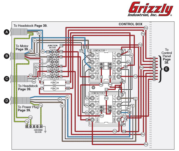
Example - my Griz G0519 mill
As wired from factory:
G0519_AsBuiltWiring.jpg


After installing VFD
G0519_wiring.jpg


> From what I'm reading I'll have to get an actual phase converter and not the VFD if
>I want to run just the individual power cord.

This is correct - unless you want to re-wire the machine controls, you need a phase converter. And not that the static phase converters fall about 50% short on power from what I read. So at least double the size you think you need for a static.
 
Last edited:
To avoid these ads, REGISTER NOW!
Top Bottom