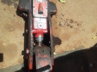
Who repairs old floor jacks? I have a Blackhawk S4 4-ton jack that would raise and lower but not lift more than about 150 pounds. I bought a seal kit for it (200 bucks!) and it still doesn't lift. It looked to me like it was bypassing internally. I tried to attach a video showing the oil pumping out of the overflow valve but I couldn't figure out how to do it (I can't even fix a floor jack). I removed the check balls again and burnished the seats with a bronze bore brush and then gave them all a tap with one of the old balls. I have a WW2 half-track that weighs about 8-1/2 tons and a 3-ton Hein-Werner jack I have will begrudgingly lift one corner of it. I tried the Blackhawk and the work on the check balls seemed to help but it was harder to pump than I thought it should be and wasn't raising much. Then the gland nut blew out of the cylinder. Apparently the packing is working! The relief valve apparently is not. Now I need to buy or make a new gland nut and still don't know what the problem is. I'm not on fire to ship this anywhere to get repaired, but it's absolutely no good the way it is and I'm not sure where to go from here. Does anybody have any suggestions or directions on what could be wrong and how to fix it? Or know of a repair shop near So. Calif.? Thanks for any help!

You are using an out of date browser. It may not display this or other websites correctly.
You should upgrade or use an alternative browser.
You should upgrade or use an alternative browser.
Vintage floor jack repair?
- Thread starter olddog1
- Start date
paulsomlo
Well-known member
"the gland nut blew out of the cylinder"? Isn't that a threaded part? Where'd you buy the seal kit from? I think you're gonna have to figure out how to post video/pictures.
Thanks for you help, Paul. Yes, it's a threaded part. No whimp, either - it's pretty robust. Non-magnetic, so I thought it was aluminum, but it's pretty heavy. Anyhow, it ripped the threads right off it. I got the seals from Tools And Hydraulics in Chattanooga. There's an eleven year old kid up the road who can maybe show me how to do the pictures. It says the pictures have to have a "url", whatever that is. If I can figure that out, I'll attach some photos of the mess."the gland nut blew out of the cylinder"? Isn't that a threaded part? Where'd you buy the seal kit from? I think you're gonna have to figure out how to post video/pictures.
paulsomlo
Well-known member
Try the box to the lower left that says "Attach files" - I'll add a screenshot here of what it looks like. How are you posting here - with your phone or computer?

Computer. I'll try that.Try the box to the lower left that says "Attach files" - I'll add a screenshot here of what it looks like. How are you posting here - with your phone or computer?
paulsomlo
Well-known member
OK - you just need to get the pictures from your phone or camera to your computer.


paulsomlo
Well-known member
ajchien
Well-known member
Last time I looked around SoCal, there was:
Lazzar https://www.hcrcnow.com/?srsltid=AfmBOoouIdf3K-G7JF8FIITqLbnxx1BiXqxIoLSZ77RAdtC1qbXjM0pF who is in Long Beach. His website also has a pretty extensive online catalog of old jack manuals /schematic drawings that you can search through. As I’m looking through the list, there seems to be a few variants of the Blackhawk S4 … This is his link to the S4 H - https://media.hcrcnow.com/uploads/drawings/s4instructionsfrontandrear.pdf
looks like part #9 - S4-21.2
and there is also Jack X change https://jackxchange.com/ in Anaheim.
However, I don’t know if either of them are the business of fixing/making a new gland nut. It’s possible those guys might have a donor parts jack laying around, or maybe they can refer you to a machinist that can make the part.
BTW … those pics … that’s pretty impressive.
Lazzar https://www.hcrcnow.com/?srsltid=AfmBOoouIdf3K-G7JF8FIITqLbnxx1BiXqxIoLSZ77RAdtC1qbXjM0pF who is in Long Beach. His website also has a pretty extensive online catalog of old jack manuals /schematic drawings that you can search through. As I’m looking through the list, there seems to be a few variants of the Blackhawk S4 … This is his link to the S4 H - https://media.hcrcnow.com/uploads/drawings/s4instructionsfrontandrear.pdf
looks like part #9 - S4-21.2
and there is also Jack X change https://jackxchange.com/ in Anaheim.
However, I don’t know if either of them are the business of fixing/making a new gland nut. It’s possible those guys might have a donor parts jack laying around, or maybe they can refer you to a machinist that can make the part.
BTW … those pics … that’s pretty impressive.
Last edited:
Thank you guys for your help! I sure appreciate it. I think you're right about the nut material being zinc, Paul. It has a part number 21-3 cast into it and I've been searching that. Thanks for the links, ajchien. I contacted Lazzar yesterday on their website and I hope to get a reply on Monday. I didn't know about jackxchange. I'll try them Monday also. I can machine a new nut if necessary (a steel one!) but I'll give it a few days to see if someone has one. Never know! The nut is the easy part - I still don't know why the jack doesn't work right. I hope one of those two outfits can help with it. If not, I can tell you I'm gonna be cracking the lead seal and backing the relief valve off a lot before I try lifting with it again! I thought it'd be fun to resurrect this classic old jack... I don't know why I thought that... 
Last edited:
paulsomlo
Well-known member
Regarding the nut, try Hydraulic Parts Supply in Sawyer KS - (620) 594-2247. A member recently sourced a part for their jack from them - $35 vs. $200+ at Lazzars.
ajchien
Well-known member
Not being familiar with the Blackhawk S4 jack…
On that online S4 H schematic drawing, on the bottom right is a cross section of the hydraulic block, it identifies an overflow (left most) and a safety valve (at the top of the second from right valve). It description of operation says it’s a 2 speed pump, quick lift with no load and less lift/more mechanical advantage with load. I only see one pump piston in the schematics.
This is my best *guess* after looking at it for a half hour … I propose to you that the oil enters the hydraulic block from the bottom and gets sucked into the pump through the right most valve. The oil gets pumped into the middle two valves which then uses a combined channel to send the oil to the lifting plunger cylinder. When a load is met, I am assuming that the left of the middle two valves closes, and any extra pumped oil gets sent through the overflow valve back to the reservoir; while the right of the middle two valves continues sending oil to the lifting plunger when lifting the load.
If you can prove that the above is how it works, then I’d say you might have 2 problems -the poor lifting could be that the overflow valve is open too easily, causing you to bypass when without load AND the safety valve is set too tight, leading to the blow out of your gland nut.
On that online S4 H schematic drawing, on the bottom right is a cross section of the hydraulic block, it identifies an overflow (left most) and a safety valve (at the top of the second from right valve). It description of operation says it’s a 2 speed pump, quick lift with no load and less lift/more mechanical advantage with load. I only see one pump piston in the schematics.
This is my best *guess* after looking at it for a half hour … I propose to you that the oil enters the hydraulic block from the bottom and gets sucked into the pump through the right most valve. The oil gets pumped into the middle two valves which then uses a combined channel to send the oil to the lifting plunger cylinder. When a load is met, I am assuming that the left of the middle two valves closes, and any extra pumped oil gets sent through the overflow valve back to the reservoir; while the right of the middle two valves continues sending oil to the lifting plunger when lifting the load.
If you can prove that the above is how it works, then I’d say you might have 2 problems -the poor lifting could be that the overflow valve is open too easily, causing you to bypass when without load AND the safety valve is set too tight, leading to the blow out of your gland nut.
You're right - there is only one pump piston. I couldn't make heads or tails of the flow based on that drawing. I could see the passages as you described them but I didn't know the order of things. What you say makes sense. I have a video of the oil returning from the overflow valve which was happening at little resistance to lifting, not allowing any force to lift anything beyond about 150 pounds before it started to return the oil, the first of the two problems you noted. The overflow valve had a fourth 7/32" ball in it when I tore the unit down. There's no ball shown for that valve, which is a tapered seat, so I assumed it was assembled incorrectly the last time some other poor sap tried to overhaul it. I'll get the nut replaced and then set the relief valve lighter and try it again. Maybe I should get two nuts!
I'm sure grateful for all the time you spent on this and for your suggestions. Thank you!
I'm sure grateful for all the time you spent on this and for your suggestions. Thank you!
ajchien
Well-known member
well, like I said, it is a guess as to how it could work. I could be wrong. I agree that the schematic is not drawn so that it is easy to figure out what is what. I would consider blowing compressed air through passages to try to see what holes really connects to what. You’ll become the Blackhawk S4 expert on the forum after you sort it out. 
heres some general concepts I’ve seen used in jacks, which is kind of what I tried to apply to what is shown in the schematic:
when you have a quick lift jack, both the “quick lift” side and the “regular lift” side work in unison to move oil into the lifting cylinder when there is no load. When the jack encounters a load, the oil pressure in the hydraulics will overcome a spring loaded valve that will then open and bypass the “quick lift“ side and sending the oil back to the reservoir, leaving only the “regular lift” side moving oil into the lifting cylinder. The “regular lift“ side will have a much stronger spring loaded valve, usually set to the capacity of the jack and act as the “safety valve”, when overloaded it should open to decompress the pressure somewhere, back to the reservoir prevent overloading the jack.
also, the port that connects the reservoir to the pump is somewhere on the bottom, as when the jack rises, there is less oil and more air in the reservoir, and you’d like to not **** in air. Often times this port has a screen to try to filter out contaminants.
heres some general concepts I’ve seen used in jacks, which is kind of what I tried to apply to what is shown in the schematic:
when you have a quick lift jack, both the “quick lift” side and the “regular lift” side work in unison to move oil into the lifting cylinder when there is no load. When the jack encounters a load, the oil pressure in the hydraulics will overcome a spring loaded valve that will then open and bypass the “quick lift“ side and sending the oil back to the reservoir, leaving only the “regular lift” side moving oil into the lifting cylinder. The “regular lift“ side will have a much stronger spring loaded valve, usually set to the capacity of the jack and act as the “safety valve”, when overloaded it should open to decompress the pressure somewhere, back to the reservoir prevent overloading the jack.
also, the port that connects the reservoir to the pump is somewhere on the bottom, as when the jack rises, there is less oil and more air in the reservoir, and you’d like to not **** in air. Often times this port has a screen to try to filter out contaminants.
By what you described, it sounds like the bypass circuit is working the way it should. It just seems like a big leak when the handle is pumped and the oil just returns to the reservoir instead of lifting the load. I guess something's not directing the oil to the lift cylinder after there's enough resistance to the lift. There is a screen filter. I like the compressed air idea. I'll try that after I replace the gland nut and see if I can figure out who does what and when (what a mess that's gonna be). I'll let you know how it all goes. Thank you again.
paulsomlo
Well-known member
Here's a better drawing: https://media.hcrcnow.com/uploads/drawings/Blackhawk_S-4-3_Service_Jack_4_Ton.pdf
paulsomlo
Well-known member
Deleted
Thank you, Paul!Here's a better drawing: https://media.hcrcnow.com/uploads/drawings/Blackhawk_S-4-3_Service_Jack_4_Ton.pdf
ajchien
Well-known member
The second diagram that @paulsomlo linked also shows no ball under the overflow valve. So if you say a ball is there, it’s in the wrong place. Going from left to right, I see 0,1,2,1 balls. In the valve with 2 balls, it denotes a 7/32 on bottom and 5/16 on top.
There was a 5/16" ball in the overflow valve when I dismantled it. I didn't re-install it as the diagram doesn't show it, plus it's a tapered seat with a corresponding tapered pin. A ball doesn't belong there. I installed the others as you have them listed. I'm wondering if when the previous person installed the ball in the overflow valve it might have compressed the spring so much more that with the ball now removed, it caused it to have less down pressure on the valve pin making it open earlier than it should. I don't know how sensitive the valve is, but could that be a factor?
paulsomlo
Well-known member
Here's another thread on the S4, in particular, you may want to look at post #8: https://www.garagejournal.com/forum/threads/early-blackhawk-s4-repair.416582/
ajchien
Well-known member
Thanks, Paul. My head's kinda spinning trying to follow all of that! I'll double check, but I'm pretty certain I have clearance between the stems and the balls.
Hiball is using some different terminology in post #8 than in the diagrams. When he refers to speed side bypass and high side bypass, he’s talking about the overflow valve. When he talks about the overload valve, he is referring to the safety valve.
In that thread, that person has valve plugs with stems that are different lengths. In the diagrams I see so far posted the #2 and #4 stems are the same length (hopefully you’re are of the same length), while the overflow and the valve with the safety valve are clearly different.
Yes, mine are the same length. I don't recall how much, but there is definitely clearance between those two stems and the balls. I'll either order a gland nut from someone tomorrow or start making one. When it's re-assembled, I'll start by backing off the relief valve first thing. I don't know how that'll help it lift, but maybe it won't blow up again trying! 
Well, shoot. I struck out on the gland nut at Lazzar's, Jackxchange, Hydrauic Parts Supply and Tools & Hydraulics. A couple of feelers are still out and I'll give them a day or two, but it's looking like an impending trip to the steel supply place and then some quality time on the lathe. Could be worse!
paulsomlo
Well-known member
Not surprising - other than attached to another S4, I doubt that one exists.
I agree. I'd have been shocked to find an NOS one. I was hoping one of the shops might have a parts jack with one on it.Not surprising - other than attached to another S4, I doubt that one exists.
ajchien
Well-known member
@olddog1 asked me to talk about floor jack valves. I think it would probably be good to review a basic single pump system before tackling on systems with a quick lift.
here is a diagram from a Hein Werner 93642:
in this picture... The green mark is over where the port for the pump is located. The blue arrow is where oil comes in from the reservoir, the red arrow is where oil goes out to the lifting cylinder. Above check ball 33 is the safety/overload valve which is closed by a spring. That valve will open when the pressure in the oil exceeds the rating of the jack.
when the jack handle gets pulled up, the pump ***** in oil into the green port. The oil comes through the bottom, past check ball 34. check ball 35 is shut closed from the suction.
when the jack handle is pushed down, oil comes out of the green port, check ball 34 gets closed, and check Ball 35 open pushing the oil into the lift cylinder.
if ever the pressure of the oil reaches the capacity of the Jack, which the spring is set on check ball 33, check ball 33 opens up and then allow oil to go back into the reservoir through that valve.
here is a diagram from a Hein Werner 93642:
in this picture... The green mark is over where the port for the pump is located. The blue arrow is where oil comes in from the reservoir, the red arrow is where oil goes out to the lifting cylinder. Above check ball 33 is the safety/overload valve which is closed by a spring. That valve will open when the pressure in the oil exceeds the rating of the jack.
when the jack handle gets pulled up, the pump ***** in oil into the green port. The oil comes through the bottom, past check ball 34. check ball 35 is shut closed from the suction.
when the jack handle is pushed down, oil comes out of the green port, check ball 34 gets closed, and check Ball 35 open pushing the oil into the lift cylinder.
if ever the pressure of the oil reaches the capacity of the Jack, which the spring is set on check ball 33, check ball 33 opens up and then allow oil to go back into the reservoir through that valve.
Attachments

ajchien
Well-known member
So here is that hydraulic block for the S4. It is a single pump quick lift system. That means it has to have a way of pumping a lot of oil with no load for the quick lift, and then switching to pumping less oil when a load is lifted to gain an additional added hydraulic/mechanical advantage to multiply your force. Caveat here is that I’ve never been inside an S4. However, this is how I believe the valves work based on how the diagram is drawn.
the reservoir entry is where the blue arrow is. When the pump ***** up oil, the oil travels to the right of the schematic and up past check ball 7. My green arrow is marking a hole at the 10-11 o’clock area of ball 7. That’s where the oil goes into the pump.
when the pump pushes oil out, check ball 7 closes, and i believe the oil should come back into the picture where the two yellow arrows are pointing. The oil then flows past check balls and into the port marked with the red arrow, and heads to the lifting cylinder.
when the jack saddle meets a load, the oil pressure will increase. At a certain pressure, it will exceed the strength of the spring 91 keeping the overflow valve 90 closed. Thus, the overflow will open and all the oil in that pathway is going back to the reservoir. You have now switched from quick lift to a slower lift with greater mechanical advantage.
at the same time that oil is passing though the overflow valve, the other valve (the tall one) is still pushing oil into the red port into the lift cylinder. Since the pressure is now higher, this closes that check ball in the second to left most valve.
if the oil pressure becomes greater than the capacity of the jack, there is another valve (aka safety valve) 109/110 that should open sending oil back to the reservoir (instead of blowing out the gland nut).
said in a different way, during quick lift, there are 2 parallel channels sending oil into the lift cylinder. When the jack meets a load, one channel sends oil back to the reservoir through the “overflow valve” while the other channel continues work to send oil to the lift cylinder. If the capacity of the jack is exceeded, then the jack stops lifting as the “safety valve” opens and both channels are now sending oil back to the reservoir.
the reservoir entry is where the blue arrow is. When the pump ***** up oil, the oil travels to the right of the schematic and up past check ball 7. My green arrow is marking a hole at the 10-11 o’clock area of ball 7. That’s where the oil goes into the pump.
when the pump pushes oil out, check ball 7 closes, and i believe the oil should come back into the picture where the two yellow arrows are pointing. The oil then flows past check balls and into the port marked with the red arrow, and heads to the lifting cylinder.
when the jack saddle meets a load, the oil pressure will increase. At a certain pressure, it will exceed the strength of the spring 91 keeping the overflow valve 90 closed. Thus, the overflow will open and all the oil in that pathway is going back to the reservoir. You have now switched from quick lift to a slower lift with greater mechanical advantage.
at the same time that oil is passing though the overflow valve, the other valve (the tall one) is still pushing oil into the red port into the lift cylinder. Since the pressure is now higher, this closes that check ball in the second to left most valve.
if the oil pressure becomes greater than the capacity of the jack, there is another valve (aka safety valve) 109/110 that should open sending oil back to the reservoir (instead of blowing out the gland nut).
said in a different way, during quick lift, there are 2 parallel channels sending oil into the lift cylinder. When the jack meets a load, one channel sends oil back to the reservoir through the “overflow valve” while the other channel continues work to send oil to the lift cylinder. If the capacity of the jack is exceeded, then the jack stops lifting as the “safety valve” opens and both channels are now sending oil back to the reservoir.
Attachments

Last edited:
RTM
Well-known member
Thanks for this, I have a two speed import I need to look at to make the lifting easier. This will be a good guide.So here is that hydraulic block for the S4. It is a single pump quick lift system. That means it has to have a way of pumping a lot of oil with no load for the quick lift, and then switching to pumping less oil when a load is lifted to gain an additional added hydraulic/mechanical advantage to multiply your force. Caveat here is that I’ve never been inside an S4. However, this is how I believe the valves work based on how the diagram is drawn.
ajchien
Well-known member
Thanks for this, I have a two speed import I need to look at to make the lifting easier. This will be a good guide.
the general concepts of having one way check valves to direct oil + spring loaded valves to act as a quick lift switch or safety valve are common concepts.
the specifics of where all the oil channels in the hydraulic block and where all the valves (which valve is which?) are located are variable depending on the manufacturer.
there are 2 common two speed import jack styles on the market. One is dual pump, the other is a single pump/dual lifting cylinder. Both of them have hydraulic blocks that are different from the S4 diagram above.
paulsomlo
Well-known member
Is the S4 pump some sort of concentric design?
Thanks so much for all your time and work you put into this, Alex. It is very much appreciated. As soon as I get the nut made, I'll find out why mine's not switching from overflow to heavy lifting and let you all know what I found with it. Again, thank you!
ajchien
Well-known member
Is the S4 pump some sort of concentric design?
Im not sure what a concentric design is. The S4 diagram is certainly new to me, I have not seen anything exactly like that before. Most of my amateur tinkering has been on walker/lincoln and the chinese clones of the japanese import (what Hiball calls the Yasui) design.
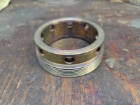
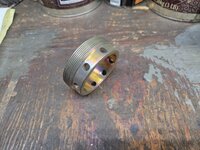
Well I finally got other real-life stuff taken care of so I can get back on this jack repair. I wound up machining a new gland nut out of 1018 CR steel. I dare it to try to blow this nut out. I plated it with zinc followed by a sodium dichromate treatment. Now back to trying to figure out why it won't lift properly.
Attachments


paulsomlo
Well-known member
Very nice job on that nut.Well I finally got other real-life stuff taken care of so I can get back on this jack repair. I wound up machining a new gland nut out of 1018 CR steel. I dare it to try to blow this nut out. I plated it with zinc followed by a sodium dichromate treatment. Now back to trying to figure out why it won't lift properly.
I finally found the problem causing the hydraulic issue with this jack. I don't know how many times I went through the check balls, checking that they were seating, lifting, oil going where it's supposed to, etc. I wish I could blame it on something else, but the problem appears to have been with my installation of the chevron seals in the lift ram. I disassembled the ram and the packings were torn and there were leather fragments from them scattered all over behind the preload adjuster. Beats me why, but I must've screwed something up during the assembly. I cleaned out the leather crumbs and replaced the damaged seals. Now with the proper assembly and preload, it runs as it should. Well, more or less - I lifted a front corner of my half-track, which weighs around 8-1/2 tons, and it bleeds about 1/8" in ten minutes. I can live with that, but I'll watch for any leakage around the lift ram in case the packings may need a little more squeeze. What an exercise this has all been. But I did learn a lot, and now I do know how this 2-stage jack works!