To avoid these ads, REGISTER NOW!

Vintage grinder lighting question...

Ststephen7

Well-known member
Joined
Sep 24, 2016
Messages
165
Location
Elkins Park, PA
Hey guys,

I am restoring this old B & D 10" 3 phase grinder. I'm almost ready to start assembling it, and I have a question about wiring the lights.

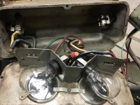
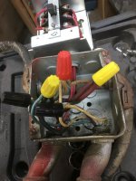
I'll attach pictures to describe what I found... Each light housing had 4 wires going to it from a box on the back of the grinder. Nothing was grounded. It uses normal appliance bulbs (120v ac), so I have no idea why it was wired the way it was. And I would like to simplify it.

Here are a couple of pictures of what I found:

IMG_5239.jpg

IMG_5247.jpg

IMG_5249.jpg

Is there any reason I should not simplify this, with just a hot/neutral/ground to each housing? I'll have to install a ground terminal since nothing was grounded...

And... I was planning on leaving the mercury switches in place, however now I'm thinking to just have the lights come on whenever the grinder is powered on... any thoughts on why not always have the lights on? I'm using LED appliance bulbs, so they will last a long time.

Thank you!
Steve
 
To avoid these ads, REGISTER NOW!

Bert_

Well-known member
Joined
Dec 24, 2016
Messages
9,758
Location
NW Iowa
It's not real clear in the picture but it almost looks like the bulbs are in series. If this is a 240V grinder then that kind of makes sense since there would be no neutral to get 120v. (2) 120V bulbs of the same size wired in series would work fine on 240V, not sure if an led, with it's electronic driver, will like it though.

Where does the other end of that cord go? that might held explain why it's wired the way it is.
 

BillK

Well-known member
Joined
Aug 24, 2006
Messages
9,349
Location
Beautiful Southern Maryland
Are you keeping it three phase or changing it to single phase ?

They might have each light on a different phase to spread the load evenly.
 
Last edited:
OP
S

Ststephen7

Well-known member
Joined
Sep 24, 2016
Messages
165
Location
Elkins Park, PA
It's not real clear in the picture but it almost looks like the bulbs are in series. If this is a 240V grinder then that kind of makes sense since there would be no neutral to get 120v. (2) 120V bulbs of the same size wired in series would work fine on 240V, not sure if an led, with it's electronic driver, will like it though.

Where does the other end of that cord go? that might held explain why it's wired the way it is.

Thank you both!

See... this is why I ask. I know so little. I mean I can do normal home wiring... it's so simple, and relatively safe just following the rules.

Yes, it is 3 phase 240. I understood that one could not change a motor from 3 phase to single phase, so it's staying 3 phase 240. The grinder is essentially the motor with guards, wheels and tool rests.

I tried to wire the LED's in series (with 110) and no... they would light up for a split second and then just lightly glow.

Not only was each light housing wired slightly differently, but they also had different tags as shown

IMG_5299.jpg
IMG_5298.jpg

Why in the world would someone wire them so differently? Probably from the factory, right? Why?

I guess in the end it doesn't matter why. I'd like to use these super bright LED appliance bulbs. Is there any reason why I should not run a new 110 wire up to each housing instead of putting it back the way I found it?

Does 240 3 phase even have a neutral? If not I guess I'll have to run a separate wire just for the lights... maybe that's why they did t?

Anyway, this is where the wires come from... a junction box on top of the larger (what do you call that larger box with the reset button for 3 phase?). In the pictures I've already removed the 3 wires that brought in 3 phase power, entering from the top and running straight through the junction box, down into the larger box.

I took lots of pictures and a few videos so I would be able to replicate what I found if I choose to, so let me know if you need more info in order to send me in the right direction.

Thank you so much!

Steve
 

Attachments

  • IMG_5423.jpg
    IMG_5423.jpg
    102.5 KB · Views: 11
  • IMG_5424.jpg
    IMG_5424.jpg
    96.5 KB · Views: 13
  • IMG_5428.jpg
    IMG_5428.jpg
    134.4 KB · Views: 11
To avoid these ads, REGISTER NOW!

BillK

Well-known member
Joined
Aug 24, 2006
Messages
9,349
Location
Beautiful Southern Maryland
What I would do before anything else would be to draw out a wiring diagram. Trace each wire and show exactly where they go. Kind of strange that one of the tags shows 110 and the other one 220. Are you sure both bulbs are the same ? Have you actually had this thing hooked up and running to see if it all worked before you started restoring it ?
 
OP
S

Ststephen7

Well-known member
Joined
Sep 24, 2016
Messages
165
Location
Elkins Park, PA
What I would do before anything else would be to draw out a wiring diagram. Trace each wire and show exactly where they go. Kind of strange that one of the tags shows 110 and the other one 220. Are you sure both bulbs are the same ? Have you actually had this thing hooked up and running to see if it all worked before you started restoring it ?

Yes, all of the bulbs are 120v appliance bulbs (I just checked). Would they work without a neutral? Does 3 phase include a neutral? It has to, right?

I've done a TON of googling and I have not been able to find another grinder like this one, nor any information on it.

I was not able to see it work before taking it. I traded future welding work for it, and it was on the back of an open trailer so... yeah.

I did find someone near me with 3 phase, so I took the motor over and it worked fine (needed new bearings, and i have those). All of the parts are here... it's a beauty (or will be)!

I took enough pictures and video that I can hook it back up exactly as I found it, however... the rest of the story... on top of the 2 boxes shown above there was a 3 phase on/off switch. There is also another switch that sends 2 white wires from the larger box (shown above) up into ONE of the light housings AND there was a mercury switch inside each housing, so the lights went on/off when you tilted the housing/glass shield.

I'm betting the mercury switches are original, and the second switch is not.

I wired each side (the 2 light sockets and mercury switch) on my bench with 120v and they worked fine the way I had them wired. The mercury switches had a limited range... on was only perhaps 30 to 40ish degrees of tilt, and then back off again, and I can live with that if I decide to put them back in.

To my original question... I am not 'restoring' this back to its original state, especially since I don't know for sure that that was (as far as switches and the light wiring goes). So... if I decide to just run a simple 120 line to work the lights will I need a separate 120v line just for the lights? Would that be weird?

If yes (I would need a separate 120v line just for the lights), I might just put it all back the way I found it, but perhaps leaving out the additional switch and box, and just rely on the mercury switches, and see if that works. I don't currently have 3 phase so I can't wire it up and see what works and what does not.

If it's unreasonable to really answer my questions without a wiring diagram (of the way I found it) I can draw it up, and we can go from there. It just seems unusually and unnecessarily complicated, with both the mercury switches and the additional switch, and I'd like to simplify it if I can.
 

Bert_

Well-known member
Joined
Dec 24, 2016
Messages
9,758
Location
NW Iowa
It's possible it was originally designed for 240v bulbs but someone rewired it with the bulbs in series so that they could use common 120v bulbs. The orange wire nut seen in the picture makes me think this is the case.

Two 120 volt bulbs in series will work fine as long as they are both the same size. If one burns out they will both go out, just like Christmas lights. Stuff with electronic power supplies might not like it though, led's.

If you want to wire it normally and use 120 volt bulbs you need a neutral since the grinder would not normally have one.

Another thought that might be possible is to look for bulbs that are rated 120-277v. They could run directly on 240. This is a common rating for commercial fixtures but I'm not sure if any screw in bulbs are this way.
 
OP
S

Ststephen7

Well-known member
Joined
Sep 24, 2016
Messages
165
Location
Elkins Park, PA
It's possible it was originally designed for 240v bulbs but someone rewired it with the bulbs in series so that they could use common 120v bulbs. The orange wire nut seen in the picture makes me think this is the case.

Two 120 volt bulbs in series will work fine as long as they are both the same size. If one burns out they will both go out, just like Christmas lights. Stuff with electronic power supplies might not like it though, led's.

If you want to wire it normally and use 120 volt bulbs you need a neutral since the grinder would not normally have one.

Another thought that might be possible is to look for bulbs that are rated 120-277v. They could run directly on 240. This is a common rating for commercial fixtures but I'm not sure if any screw in bulbs are this way.

Thank you so much!

So... it sounds as if I have 2 choices:

I can use the normal 120v appliance bulbs that I found in there IF I put the wiring back the way I found it.

OR... I can switch to LED's but only with an additional 120 line to the grinder, to provide normal hot and neutral lines (because 220 motors do not use a neutral).

Is that correct? Hmmm... What would you do? Some 3 phase machines also need 120, right?

I wish I had 3 phase here so I could put it the way it was and see how it works with the mercury switches.

Either way, I think I will be removing that additional switch and box (not shown above), and just have the lights either always on when the motor is running, or switched with the mercury switches.
 
To avoid these ads, REGISTER NOW!
Top Bottom