To avoid these ads, REGISTER NOW!

Weld Callout Question

freudianfloyd

Well-known member
Joined
Feb 12, 2015
Messages
3,432
Location
Nowhere
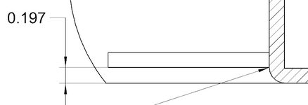
I am looking over a drawing for an engineer and trying to figure out which callout works best in this situation. This is not my part, or design, I cannot change the design, only help the designer call out the proper weld.

*Arrow side of weld joint* The designer called for a 3/16" fillet on both sides. I have looked through all my AWS standards and cannot find a good representation of this. It isn't a fillet per se, but it isn't exactly a flare-bevel either. Any ideas?
1742827623988.png
 
To avoid these ads, REGISTER NOW!

PCustoms

Well-known member
Joined
Jul 23, 2011
Messages
23,438
Location
VT
I am looking over a drawing for an engineer and trying to figure out which callout works best in this situation. This is not my part, or design, I cannot change the design, only help the designer call out the proper weld.

*Arrow side of weld joint* The designer called for a 3/16" fillet on both sides. I have looked through all my AWS standards and cannot find a good representation of this. It isn't a fillet per se, but it isn't exactly a flare-bevel either. Any ideas?

1742827623988.png

I realize you can't post more, but I'm having a hard time visualizing what that is....

Isn't that the wrong view to call out the weld?
 
OP
F

freudianfloyd

Well-known member
Joined
Feb 12, 2015
Messages
3,432
Location
Nowhere
I realize you can't post more, but I'm having a hard time visualizing what that is....

Isn't that the wrong view to call out the weld?
It is correct in calling out the top and bottom of the small plate. There is a separate callout for the edges of the plate.

It is basically a small plate welded to the side of square tubing, they just start the joint at the beginning of the square tube's radius instead of flush with the bottom of the square tube which would make it a flared-bevel-groove weld.
 

PCustoms

Well-known member
Joined
Jul 23, 2011
Messages
23,438
Location
VT
It is correct in calling out the top and bottom of the small plate. There is a separate callout for the edges of the plate.

It is basically a small plate welded to the side of square tubing, they just start the joint at the beginning of the square tube's radius instead of flush with the bottom of the square tube which would make it a flared-bevel-groove weld.
So the weld is "into the page" along the radius of the tube?

What about the top side of the plate?

Is anything else attached, or is this just a tab floating off the side of the tube?

I'll have to see if I can ask around today...
 
OP
F

freudianfloyd

Well-known member
Joined
Feb 12, 2015
Messages
3,432
Location
Nowhere
So the weld is "into the page" along the radius of the tube?

What about the top side of the plate?

Is anything else attached, or is this just a tab floating off the side of the tube?

I'll have to see if I can ask around today...
Correct, you are seeing a cutaway of the tube and the edge of the plate.

Nothing else is attached, it is just welded all around this joint.
 

PCustoms

Well-known member
Joined
Jul 23, 2011
Messages
23,438
Location
VT
Correct, you are seeing a cutaway of the tube and the edge of the plate.

Nothing else is attached, it is just welded all around this joint.

I'm thinking it would get treated as a T joint with a double fillet, though small on the radius. I'm not the AWS guy though.

Kind of a poor design IMHO. Moving up or down the thickness of the plate changes everything....
 
OP
F

freudianfloyd

Well-known member
Joined
Feb 12, 2015
Messages
3,432
Location
Nowhere
I'm thinking it would get treated as a T joint with a double fillet, though small on the radius. I'm not the AWS guy though.

Kind of a poor design IMHO. Moving up or down the thickness of the plate changes everything....
I agree, it isn't my design, and I'm not 100% sure on the intent here.
 

welder4956

Well-known member
Joined
Apr 8, 2010
Messages
3,081
Location
Birmingham, AL USA
I am looking over a drawing for an engineer and trying to figure out which callout works best in this situation. This is not my part, or design, I cannot change the design, only help the designer call out the proper weld.

*Arrow side of weld joint* The designer called for a 3/16" fillet on both sides. I have looked through all my AWS standards and cannot find a good representation of this. It isn't a fillet per se, but it isn't exactly a flare-bevel either. Any ideas?

1742827623988.png
I'm confused, your photo only shows the arrow portion of the weld symbol. Using a fillet symbol for the arrow side is a little non-conventional, but would be acceptable. The arrow side weld would not be a groove weld. It would have been better if the plate was raised up 3/16" from the radius, but if it's not your design all you can do is ask if it's OK to move it up. As it is detailed now, due to the radius the leg size may need to be increased to have the same effective throat as a 3/6" fillet.
 

Rusted Nut

Well-known member
Joined
Dec 11, 2022
Messages
1,825
Location
Northern Arizona
Those are two different welds, should have separate call outs IMO. Top is a filet, bottom would be a flare bevel. Not sure the .197 is large enough for a 3/16” weld though. Weird the designer doesn’t know the proper call out.
 

b-dog

Well-known member
Joined
Apr 24, 2015
Messages
242
Location
Lakewood, CO
Disclaimer: I'm a dumb engineer. 18 years designing things that showcase that I know nothing.

I designed something similar to this at work (aerospace ground support) and didn't know how to call out that weld. After discussing with the fab shop, I called out a fillet and they welded it up.
 
To avoid these ads, REGISTER NOW!

VR6ix

Well-known member
Joined
Mar 24, 2013
Messages
356
Location
Onterrible, Canuckistan
Weird the designer doesn’t know the proper call out.

Weird how they used .197" instead of the 5.0mm that it really is. Use dual dimensions, it's usually a single mouse click away...

Weird how that HSS tube does not conform to any industry standard for cross-section shape.

If it's steel, then the inside corner radius = material thickness thus outside radius = 2x material thickness. It's drawn with no inside rad and outside rad = material thickness. If it's aluminum, I've never seen a sharp inside corner and rounded outside corner before. Is this a custom-extruded aluminum section?

My conclusion, being an inaccurate tube profile, the actual outside radius will be different and .197" is a meaningless dimension that wont match reality. So slap a fillet-weld symbol on both sides of the line, the welders will scratch their heads for a second, call some people some vile names, then just weld all around like the goal is. Or, if it's steel HSS and they want to hold that 5.0mm dim, then the arrow-side just became a flare bevel weld, no?

Smells like imagineering to me.
 

PCustoms

Well-known member
Joined
Jul 23, 2011
Messages
23,438
Location
VT
It's drawn with no inside rad and outside rad = material thickness. If it's aluminum, I've never seen a sharp inside corner and rounded outside corner before. Is this a custom-extruded aluminum section?

Good catch!

I love it (not) when prints and models have made up shapes and inconsistencies.

Anyone know what it means when my dimensions turn different colors after I edit the model? :rolleyes:
 

PugetDude

ALLIANCE MEMBER
Joined
Mar 13, 2013
Messages
22,464
Location
Superstition Mountains, AZ
Call it out any way you want, but you're going to get a fillet on top and a hybrid flare bevel/fillet on the bottom.
Good luck getting a fillet gauge on the bottom weld.
 
OP
F

freudianfloyd

Well-known member
Joined
Feb 12, 2015
Messages
3,432
Location
Nowhere
To conclude this thread, I talked to the "engineer" and was able to get him to move it down flush with the bottom of the tube. Then is just becomes a flare bevel.

As for the .197" dimension, you are correct that it should've been 5mm. I was under the impression this was designed by one of our engineers, as an engineer brought it to me. It turns out it was just a co-op that was trying to replicate a part that was designed by our German branch hence the metric WT. We don't typically use metric dimensioning for our components, so that would explain his conversion. As for the sharp inside corners of the tube, I would chock that up to the co-op not knowing any better.

Thank you all for your help.
 

PCustoms

Well-known member
Joined
Jul 23, 2011
Messages
23,438
Location
VT
To conclude this thread, I talked to the "engineer" and was able to get him to move it down flush with the bottom of the tube. Then is just becomes a flare bevel.

As for the .197" dimension, you are correct that it should've been 5mm. I was under the impression this was designed by one of our engineers, as an engineer brought it to me. It turns out it was just a co-op that was trying to replicate a part that was designed by our German branch hence the metric WT. We don't typically use metric dimensioning for our components, so that would explain his conversion. As for the sharp inside corners of the tube, I would chock that up to the co-op not knowing any better.

Thank you all for your help.

Curious, what college is the co-op from?
 

RoninB4

Well-known member
Joined
Jul 22, 2020
Messages
3,618
Location
Under My House
I love it (not) when prints and models have made up shapes and inconsistencies.
-A product of designers/engineers or those that have never actually made things themselves.
Anyone know what it means when my dimensions turn different colors after I edit the model? :rolleyes:
-Not knowing what CAD program you're using I'd have to take a WAG.

1) It could be from the dimensions not being actually attached to the feature any more after editing the model.
2) It could be that the dimensions were part of an "auto dimension" function and editing the model means it's no longer associated
3) If you've created the dimension in the drawing, instead of specifying it in the model itself, the color change may just represent that
4) After editing the model a color change just indicates that the model/drawing need an update
5) The color change may represent that the dimension is now incorrect. That also happens (in some programs) when lines no longer connect, aren't fully constrained, or are over-constrained.

Colors are supposed to be specified by the user for modeling and drawings just like background color, line weight, and line type. Specific colors (default by the program itself) are also supposed to be a visual cue for when something is wrong or different. What program are you using?
 
To avoid these ads, REGISTER NOW!
Top Bottom