To avoid these ads, REGISTER NOW!

Welding in patch panels

MP&C

Well-known member
Joined
Oct 21, 2009
Messages
4,396
Location
Leonardtown, MD
Here's another low-buck tool I made that would help out with removing your door skins, expecially on those you want to keep intact:


Probably one of the biggest challenges in taking things apart for repairs is doing so without inflicting more damage. It's hard to use an old part for a template if you mangle it beyond recognition during removal.

This is why you never throw away Vice grips that have the rounded off teeth that have just lost their bite. The lower jaw is modified to receive the edge of the door skin...


Picture582.jpg


Then a suitable "blade" is found, with plenty of material left over for replacements....


Picture580.jpg


Picture583.jpg


Some welding and grinding, and we have a new body tool.....


Picture584.jpg


Picture585.jpg


Picture586.jpg


Starting at the corner, a diagonal slice is made in the inner panel so it will remove easier...


Picture579.jpg


....and the tool is used to gently pry up on the flange of the tailgate skin.....


Picture587.jpg


Picture588.jpg


Picture589.jpg
 
To avoid these ads, REGISTER NOW!

Nick M

Well-known member
Joined
Nov 4, 2010
Messages
83
Any tips for an area which has no acess to the back? Lower quarter panel that I patched has in one area stretched out from welding, and in another area it is low, needs to be brought out (I did not contour the patch piece enough). I do have a torch, but have never worked sheetmetal like this before. Thanks!
 

MP&C

Well-known member
Joined
Oct 21, 2009
Messages
4,396
Location
Leonardtown, MD
Got any pictures? It may have moved, shrunk, etc, but doubtful that a welding operation caused it to stretch. See post 156......
 
Last edited:

gelierb

Well-known member
Joined
Nov 16, 2010
Messages
52
Location
Redwood City, CA
"Some welding and grinding, and we have a new body tool....."

Dumb question - is that just a MIG you used for welding the tooth on?
 

henrysgarage

Well-known member
Joined
Oct 10, 2010
Messages
254
Location
Carleton Place, ON, Canada
Robert, as usual your posts are out of this world. Having read many posts on other sites and looked at the volume of info you post and the number of projects you do I wonder if you ever sleep?
 

MP&C

Well-known member
Joined
Oct 21, 2009
Messages
4,396
Location
Leonardtown, MD
Sometimes I wonder that myself Henry! :lol_hitti


Just a follow up to post 188, here's the patch panels welded in and the start of dressing the welds. Didn't get as many pics as I normally take....I guess it's just too new of a vehicle to document :bounce:


Picture048-1.jpg


Picture050-1.jpg


And excuse the cell phone pic, but here it is with some H/K sealer on the repair. The owner was needing it back, my nephew had been working on it over the holidays... We'll get some paint to match it up later this spring...


IMG00001-20110102-1922.jpg
 
Last edited:

BryGuy

New member
Joined
Jun 29, 2010
Messages
2
This thread is simply amazing. I was directed here by a friend on a Jeep forum when I posted some questions about welding sheet metal..... I just bought a mig welder last week (Lincoln 140).

Unlike the beautiful restoration jobs you guys have been doing, I mostly hack up Jeeps to get a bit more out of them offroad.

I currently cut a lot of the front quarter panel away and so of the pinch seems near the firewall and it's left an area exposed.... okay, who am I kidding, it's a big mangled hole.

Picture of the carnage:
QuarterPanelChop10.jpg


All I want to do for now is patch up the hole to prevent rusting behind the area, and to provide a bit of strength to the area since I removed some of the pinch seems. Unlike the panels you guys have been working on, I don't have access to the rear of the panel.

How should I tackle this? Any all feedback welcome.

P.S: I'm not concerned about how pretty it looks.... only that it's sealed up and adds some strength to the area. :beer:
 

e-tek

Well-known member
Joined
Dec 19, 2007
Messages
10,690
Location
Saskatoon, SK

MP&C

Well-known member
Joined
Oct 21, 2009
Messages
4,396
Location
Leonardtown, MD
E-tek, I see you found some pictures of Randy Ferguson's home-made aluminum fenders. He sure does some nice work!

Edit.....

BTW, not to diminish the benefits of O/A welding, but just to clarify, those fenders you posted pictures of were in fact TIG welded....see post three on the build thread....


http://www.metalmeet.com/forum/showthread.php?t=1121
 
Last edited:

e-tek

Well-known member
Joined
Dec 19, 2007
Messages
10,690
Location
Saskatoon, SK
Ya, I knew they where tig'd, just couldn't resist putting up something so beautiful in this thread of high-end work! That last pic looks like it was pressed in a perfect form then had the creases ironed!!! One day..... ;)
 

MP&C

Well-known member
Joined
Oct 21, 2009
Messages
4,396
Location
Leonardtown, MD
Myself and a nephew. I stay away from collision work, would rather have the challenge of bringing new life to the old stuff. Body shops don't like rust repairs or fabricating for old vehicles, so we typically don't step on each others toes. Works well for referrals....both ways.
 

MP&C

Well-known member
Joined
Oct 21, 2009
Messages
4,396
Location
Leonardtown, MD
Went to a metalshaping/body lead meet today hosted by OJ Higgins at his shop, Clarke County Speed in Berryville VA. Thought some of the details covered may help out in this thread. I did the metalshaping demos, but didn't get pics of that. Supposed to get some pictures emailed/cd mailed from another guy there, so I'll add some of those later.

First pics here are of Tom Mancuso, who used to have a body shop in Long Island and learned leading from some of the masters back in the day..

Two flanged panels were tuck shrinked to form a radius. This was to simulate the leading edge of hood halves being welded together and leaded.

Picture001.jpg


Tom using tinning butter on one half and plumbers flux (liquid) with solder on the other, to demonstrate the differences.... The liquid flux tends to get down into cracks better, for a better flow of the body lead.

Adding the lead, pushing it into the joint...

Picture003.jpg


Picture005.jpg


Picture006.jpg


Rather than use a wooden paddle and tallow, Tom prefers a vintage soldering iron that uses external heat (the torch in his other hand) It seems to do a better job of managing the heat and "puddle". Even though he claimed he hasn't leaded anything in ten years, it was like old hat to him.


Picture008.jpg


Picture011.jpg


Picture012.jpg


Picture015.jpg


Picture017.jpg


After our "hood" had a chance to cool, he demonstrated leveling the area with the vixen file.


Picture020.jpg


Our completed sample


Picture024.jpg


I think Tom enjoyed another crack at flowing some lead....

Picture025.jpg


Got some pictures during the break of some of the vintage tin outside....


Picture027.jpg


Picture029.jpg


Picture028.jpg


Picture031.jpg


Picture030.jpg


Back inside for more work on metal, Dave gives a demo using the shrinking disc.


Picture036.jpg


Picture037.jpg
 

gelierb

Well-known member
Joined
Nov 16, 2010
Messages
52
Location
Redwood City, CA
Robert,

Are there any practical applications for lead these days. Everyone says plastic filler is much better than it was in the past and considering all the safety issues inherent with lead, etc.?

Still - cool to see these guys playing around with it. Is that a oxy acetylene torch he's using or some kind of propane/mapp - looks like a big flame and only seems to have one line in the photo? Interesting the use of the iron instead of paddle/tallow - would think that would make clean-up/prep for paint a lot easier - not needing to "kill" the tallow residue?

Look forward to seeing the metalshaping demos, thanks for the effort.

Gus
 
Last edited:
Joined
Feb 2, 2011
Messages
258
Location
EARTH QUAKE SHAKE PROOF...NORTH OTAGO,WAITAKI DIST
HI FROM N.Z
HEY GR8T PAGE U PUT ON....SORRY I DON T HAVE THE PATIENCE FOR THIS WORK.

THERE IS A PAINT HERE THAT MADE ACROSS THE DITCH IN AUSSIE (AUSTRALIA) CALLED..."METALFIX", ... www. [email protected]. THATS THE ADDRESS I THINK?.

THIS PAINT IS LIKE KNO OTHER AS IT LL LAST 19 YEARS OUTSIDE AND WITHSTAND 900 DEGREE CELCIOUS.

I THOUGHT THIS MAY SOOT YOUR HOBBY..

JJ
 

e-tek

Well-known member
Joined
Dec 19, 2007
Messages
10,690
Location
Saskatoon, SK
Thanks Robert. I held a few classes last year at my shop and brought in some old-timer metal guys to help us out. I learned leading from my Dad and his men in the mid 70's. It's a fanastic medium - Very interesting to use. Did you get chance to see what the composition of the lead they where using was? It's normally 30 tin/70 lead, but I have a box of 50-50 stuff still left from the days I used it.
New "lead free" body solder (copper, Zinc and tin) is actually better, works easier, lower heat and is stronger. Not much use for lead now-a-day with plastic filler being what it is, but it's (a) nice to know how to do it, (b) still used to stick things like rads to their flanges and (c) demanded by some people.
Sure wish I could get down to some of those famous Metalmeets. In Alberta Canada there's courses one can take at the Reynold's museum, where they restore cars using the methods of the day. Great for any of you Canucks wanting to learn some basics, but didn't have much advanced metal shaping. Again, that's where is would great to attend a Metalmeet (or work a few days with Robert here!).:rocker:
 

MP&C

Well-known member
Joined
Oct 21, 2009
Messages
4,396
Location
Leonardtown, MD
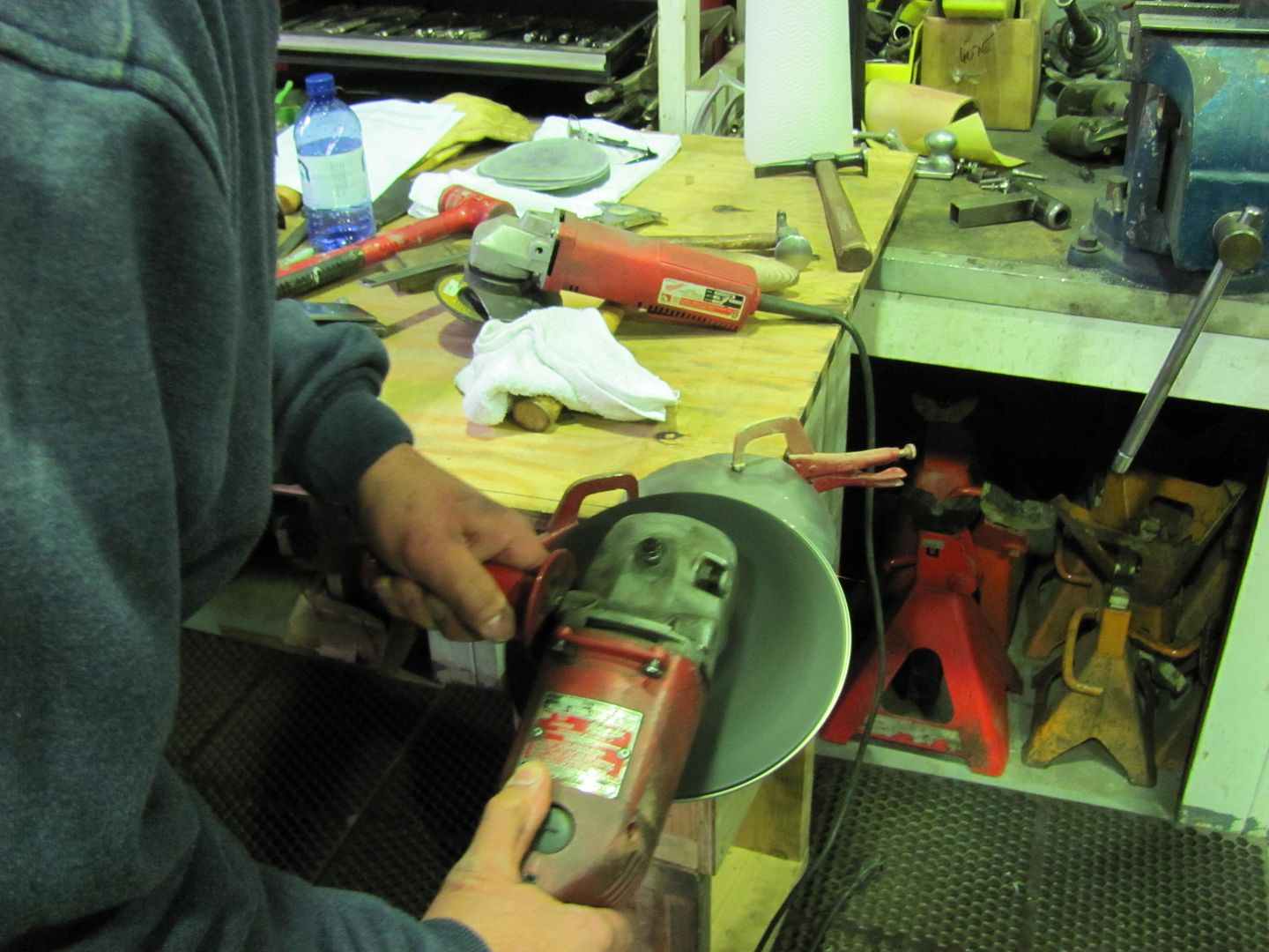
Gus, some coachbuilding outfits still use lead over plastic fillers. This was my first lesson in lead, pretty neat to see.

Etek, I think these type demos are good for all participants, including the guy giving the demo. You can do quite a quite a bit with metal, but once posed with a question, having to come up with an answer I think gives yourself a better understanding.


To expand on the pictures from OJ's event this past weekend, here is an online friendly tech thread on shrinking that should have prefaced the lead demo.


I didn't get as many pictures this past weekend (too many hammers in my hands) so this will be supplemented with some diagrams and previous pictures so we can make a good tech thread.


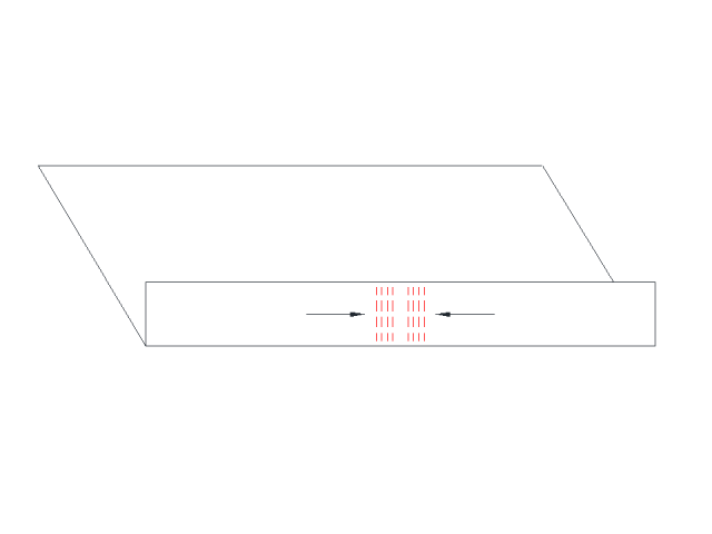
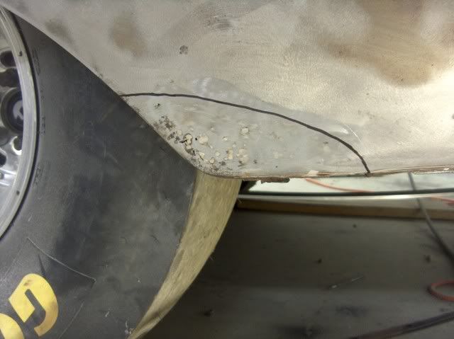
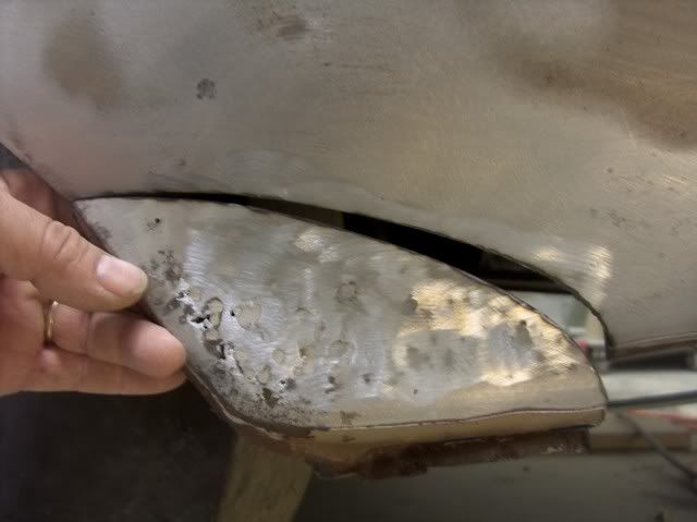
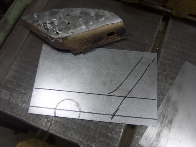
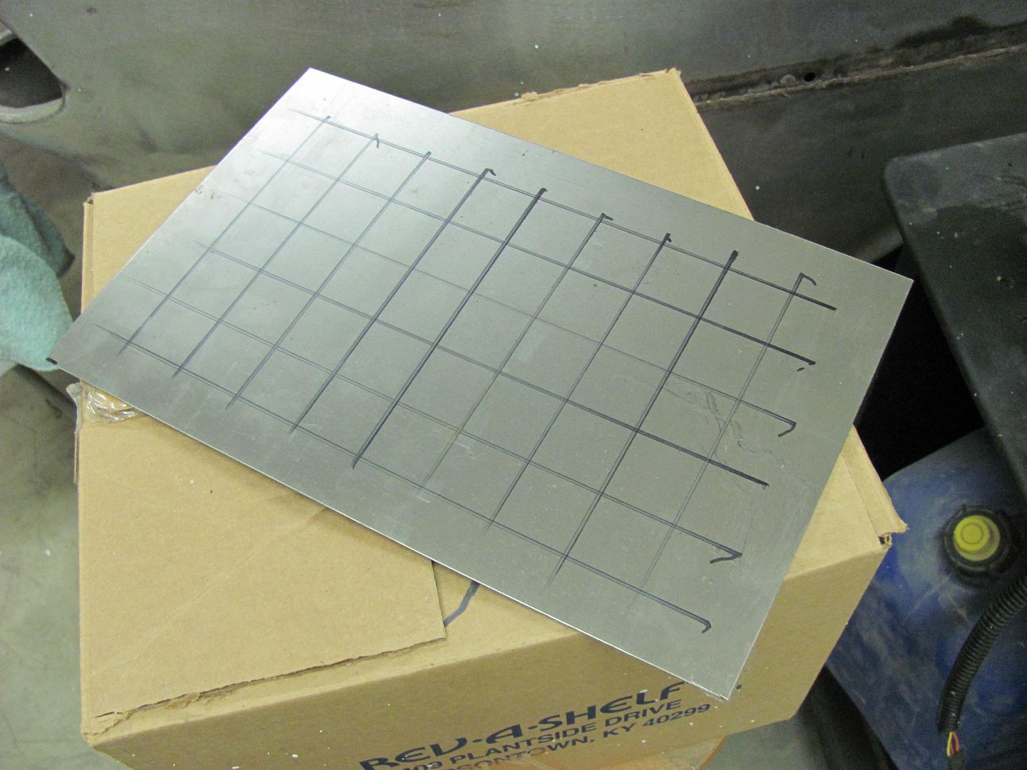
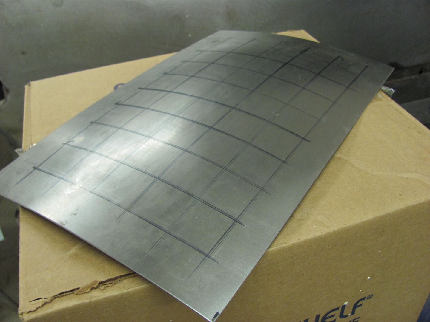
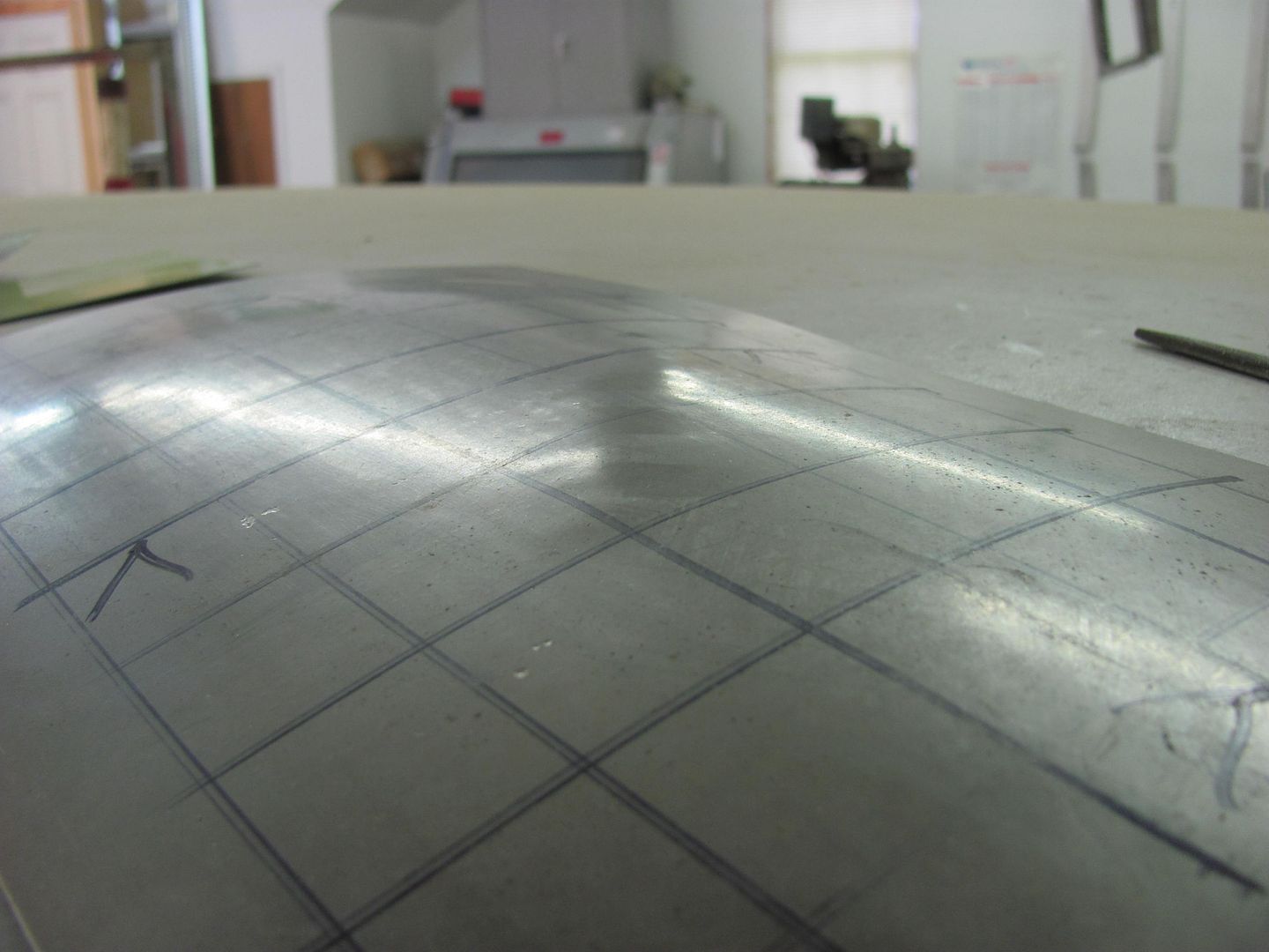
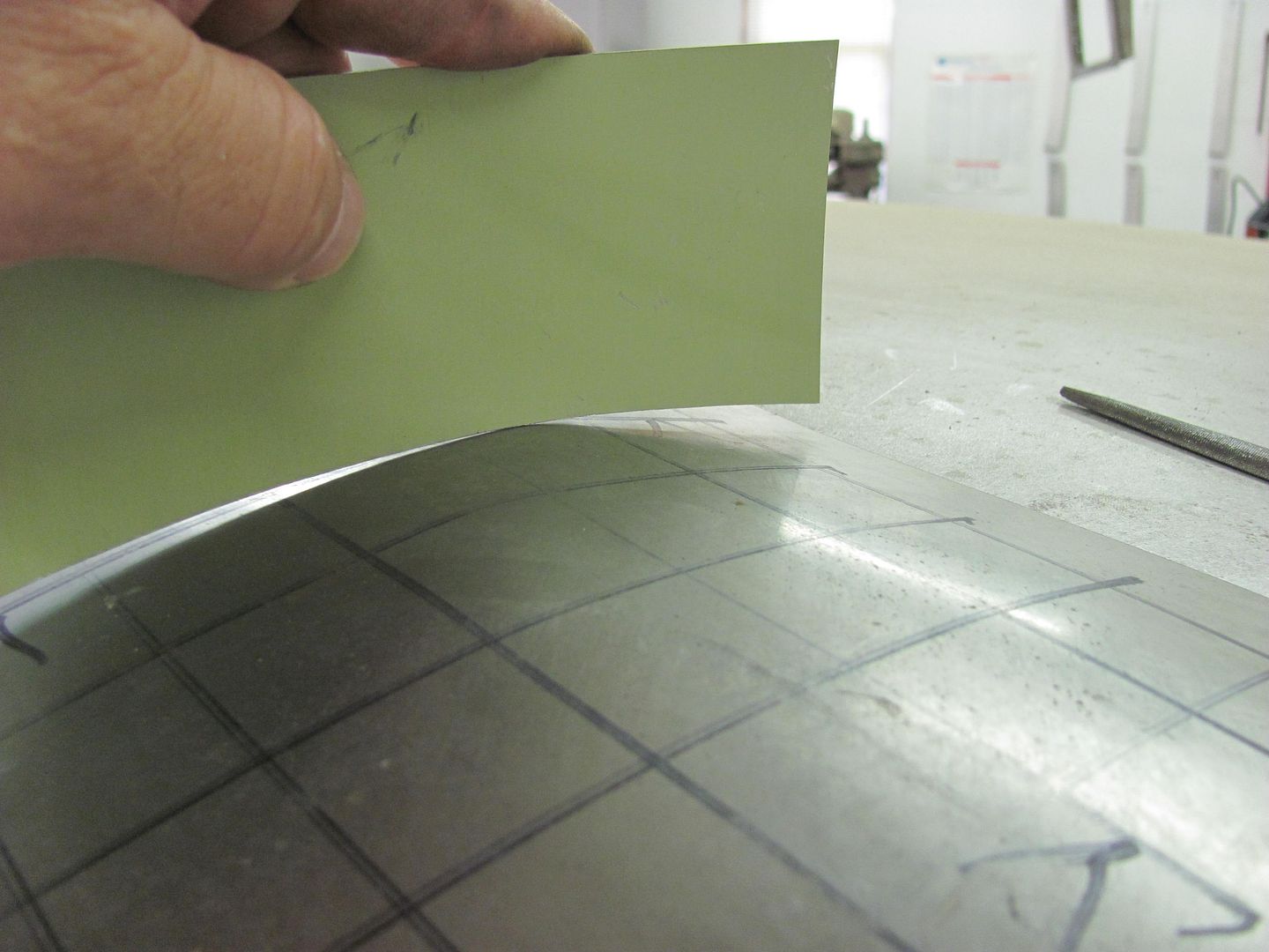
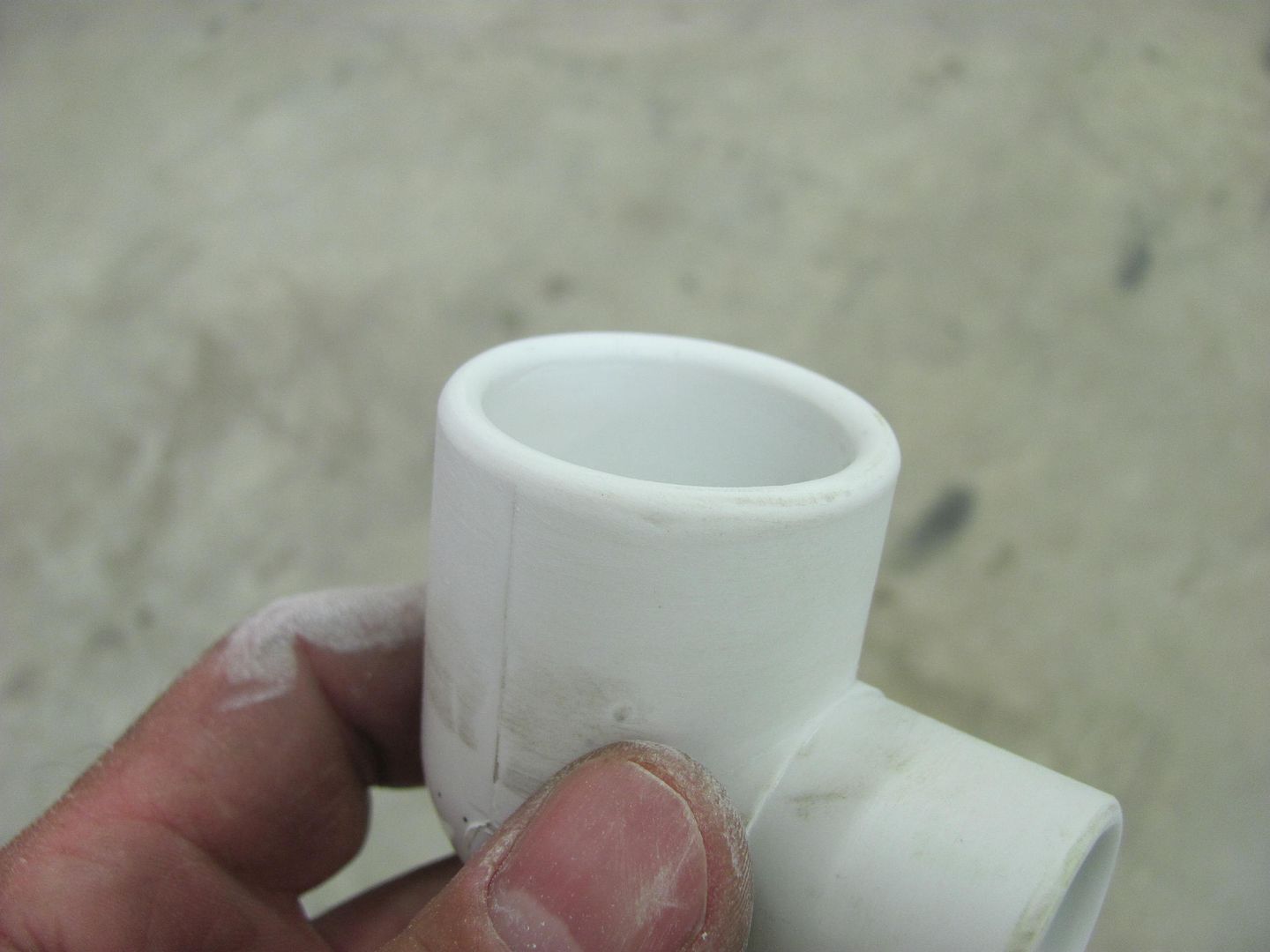
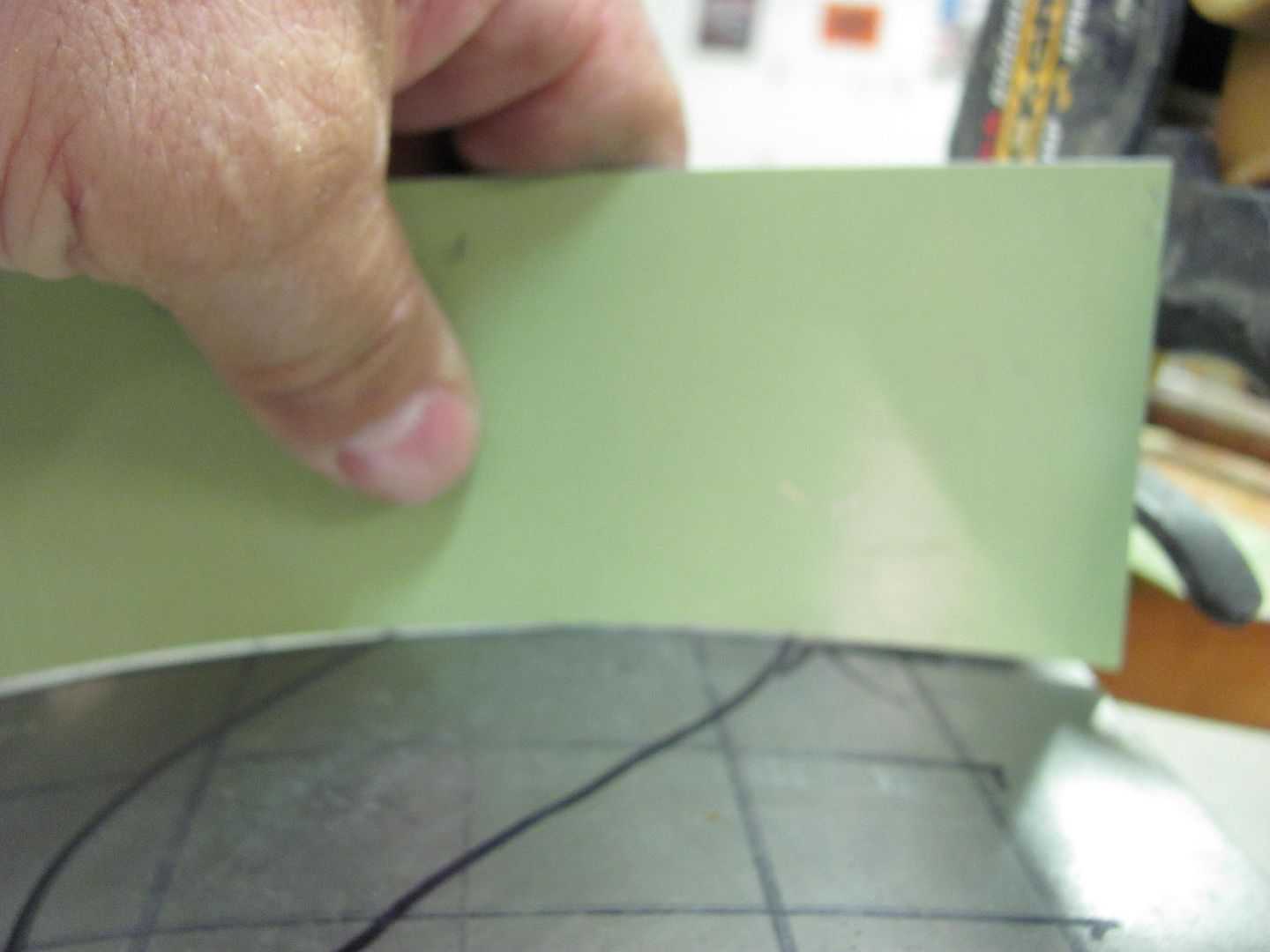
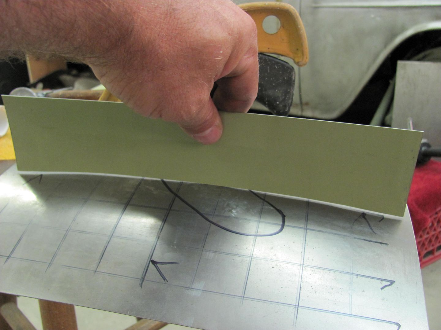
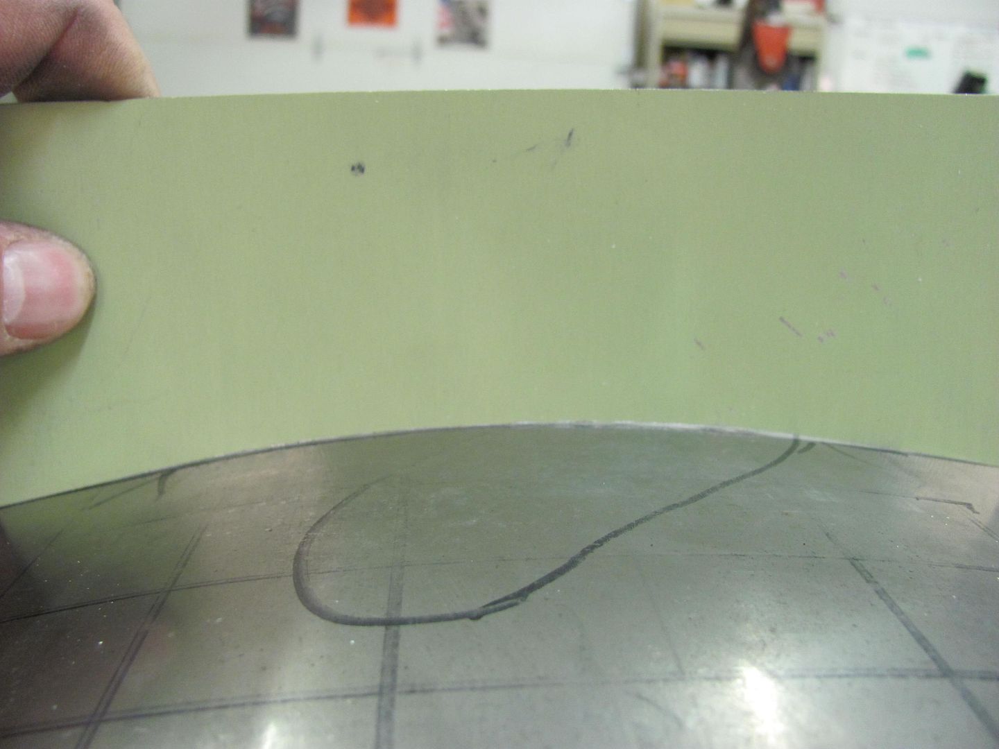
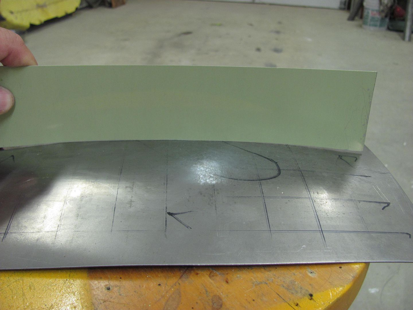
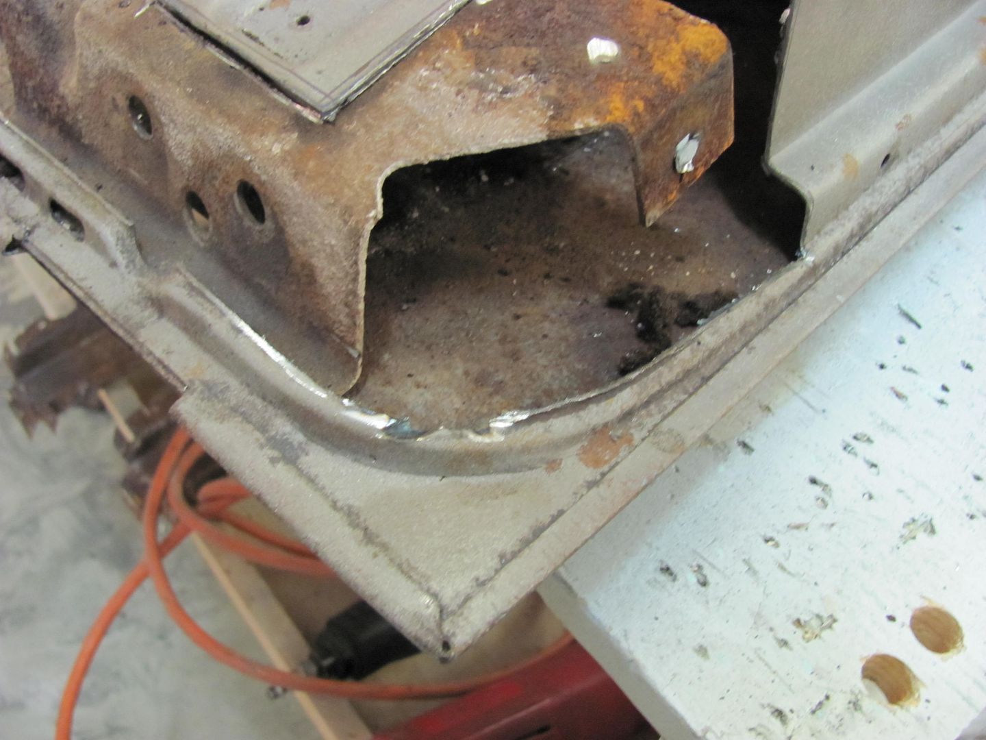
Prior to Tom showing the body lead demo, I needed to make some panels for him to work from. We decided that a curved surface, similar to the front end of a 38 Chevy and its hood halves, would be a better fixture for showing the need for flowing lead up a slight incline. I started with two equal sized panels, and bent a flange on the long edge. Then discussed some of the issues faced when shrinking a flange. For demonstration purposes, in the following example we have a 12" long panel with a 1-1/2" wide flange.

FlangedPanel.png


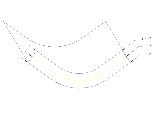
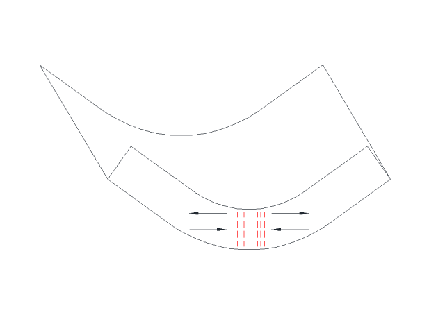
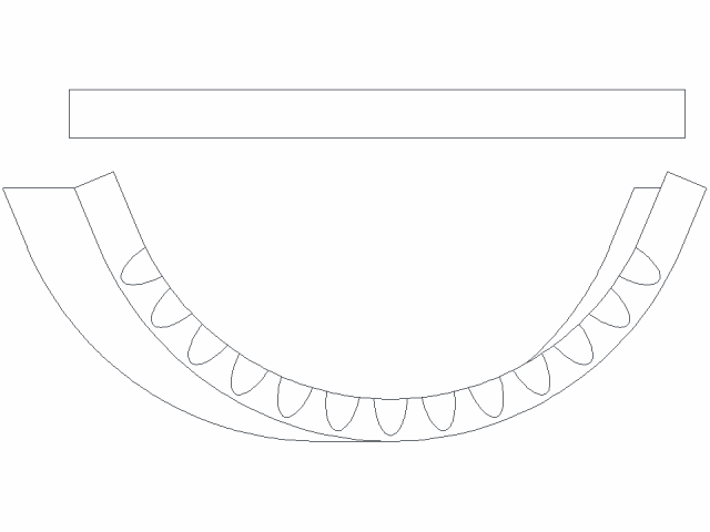
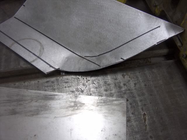
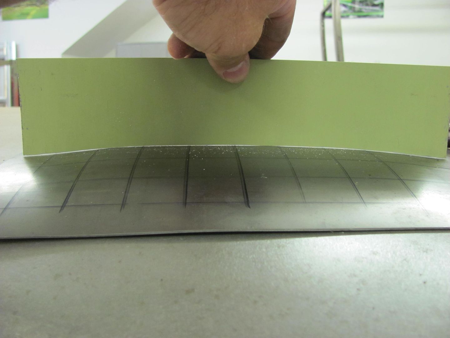
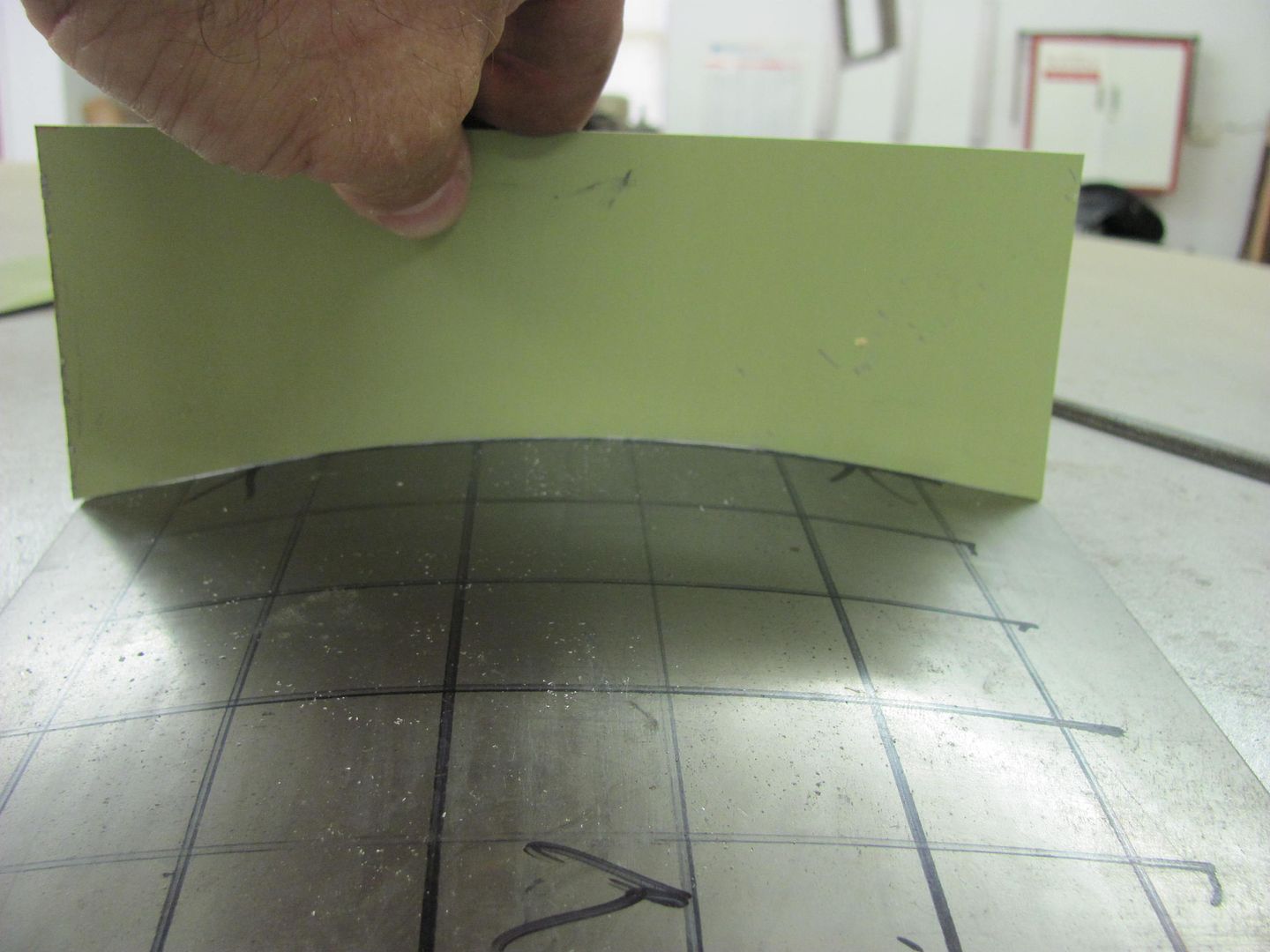
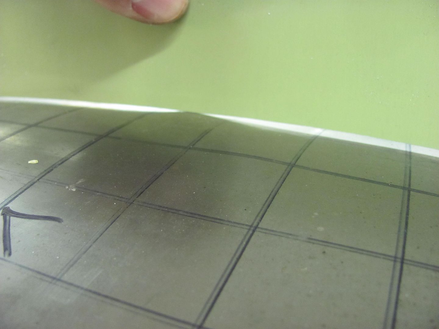
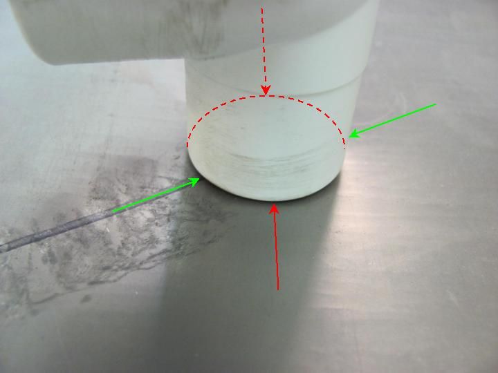
If we were to look at the same panel with a radius, formed by shrinking the flange, we would note dimensions similar to as follows:

RadiusedFlangedPanel.png


....where the 90 degree bend at the flange still retains its 12" length, the centerline of the flange in this case is shortened by almost an inch, and the outer edge of the flange shortened by almost another inch.

In working with the Lancaster/Eastwood style shrinker-stretcher machines, it is important to note that they are a linear device, the movement they introduce into the metal is in a straight line.

ShrinkDemo1.png


So that once a radius starts to form, and with the shrinking device still moving in a linear fashion, the outer edge of the flange will be put into tension as the centerline shrinks. Anyone who has used these devices will have seen this as the machine starts to lose its effectiveness.

ShrinkDemo2.png


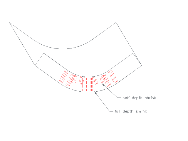
To counter this effect, we need to shrink the outer edge of the flange more than the inner. By simply alternating the depth of the shrink as shown, you can provide more shrink to the outer edge and the device will become more effective.

ShrinkDemo3.png


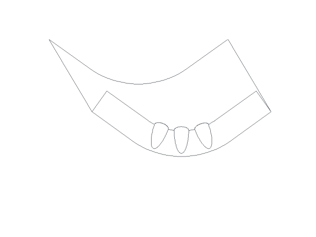
Another method of shrinking is with the use of tucks. Looking at their shape, the tuck has a wider "gather" at the edge of the flange as compared to the inside bend of the flange, so this eliminates some of the tension issues seen in the mechanical shrinker.

ShrinkDemo4.png


Where the demos this past weekend were supposed to concentrate on using only hand tools so that the participants could readily duplicate the results without the need for a major purchase, we did find the use of the Shrinker a good comparison, and by chance the tuck shrinking did prove to be faster and more effective.

For the tuck shrinking, one can use tucking forks, rounded jaw pliers (by design or modification) or special designed devices. As an example, here is a set of tucking forks I made out of some scrap metal and 5/8 bolts turned down.

Picture078-1.jpg


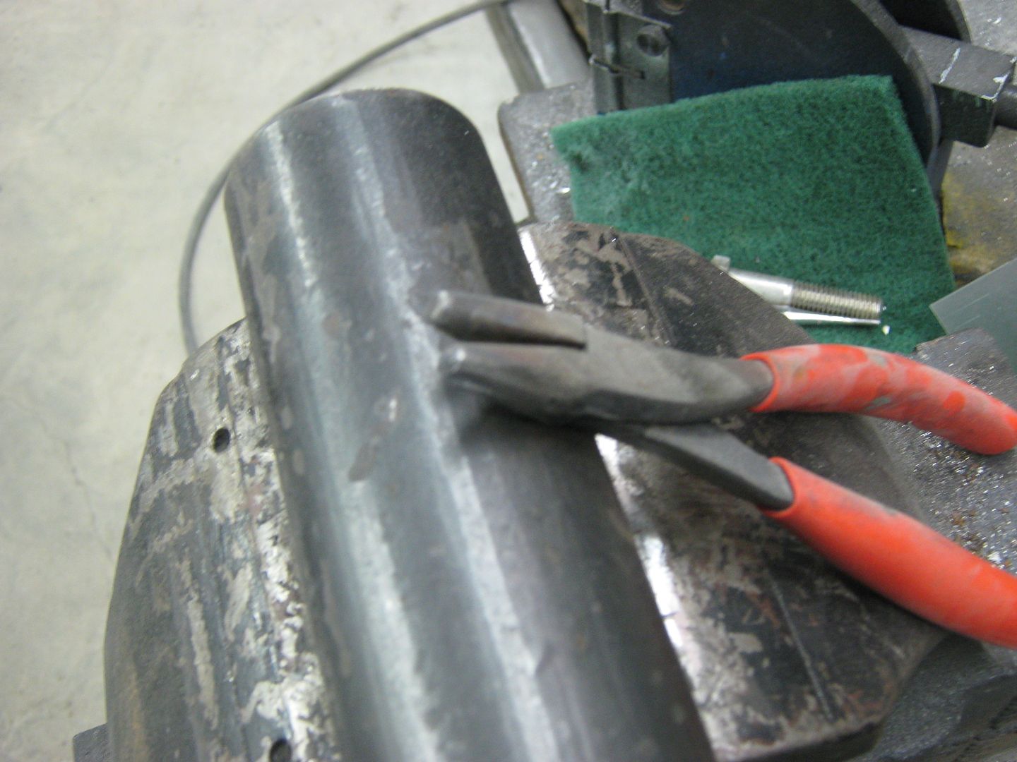
And a pair made from needle nose pliers..

Picture053-1.jpg


Probably the biggest challenge with their use is producing consistent tucks. To produce a flowing, consistent radius, we should start with consistent tucks, both in size and the spacing between them.

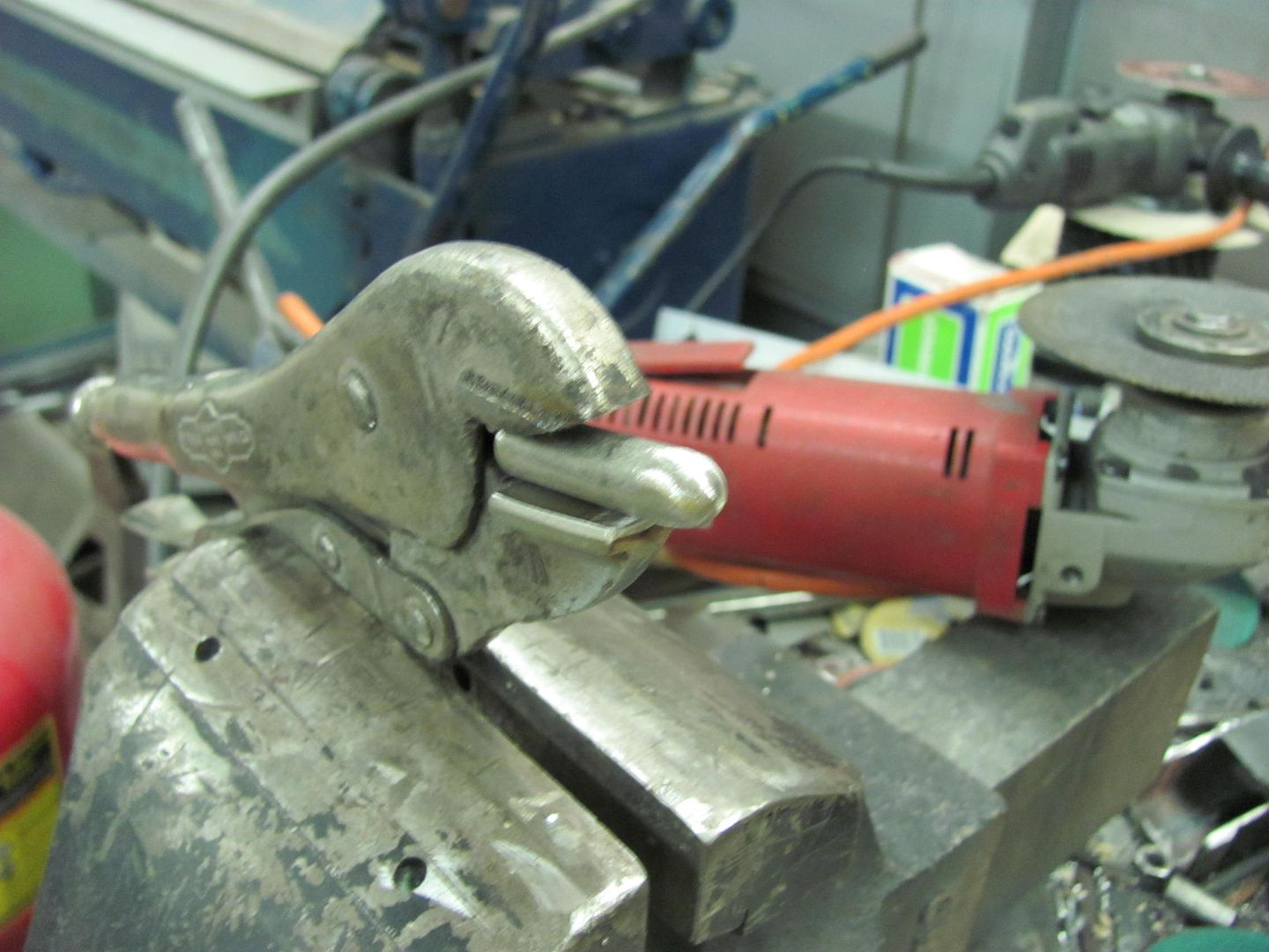
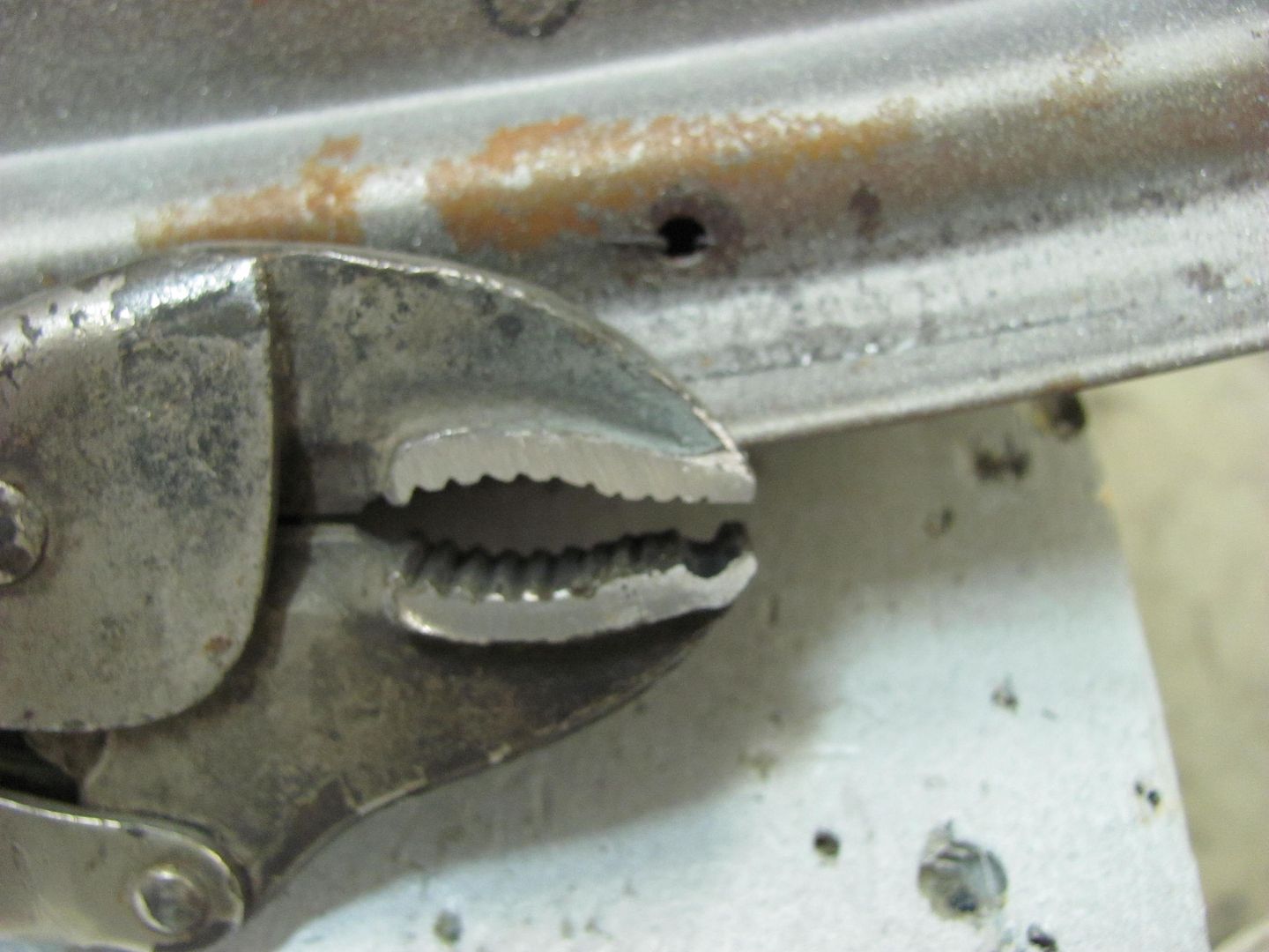
I decided to make a pair of tucking pliers out of Vice Grips, as the jaw adjustment on them would prove to give repeatable sized tucks.

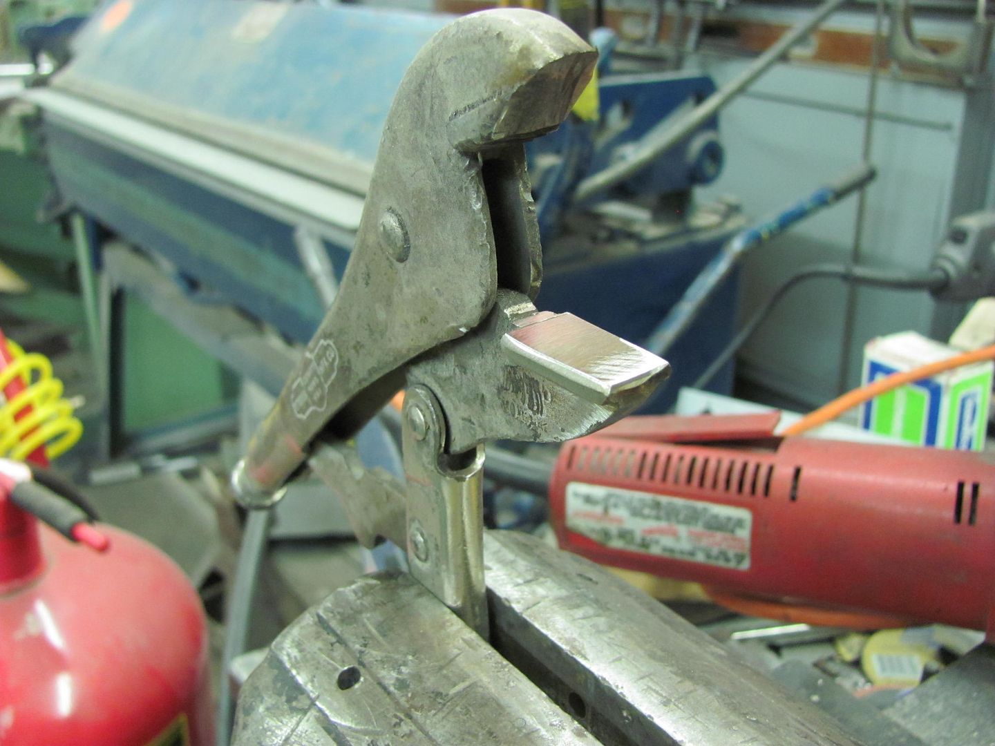
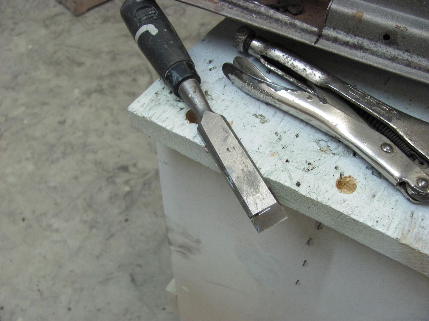
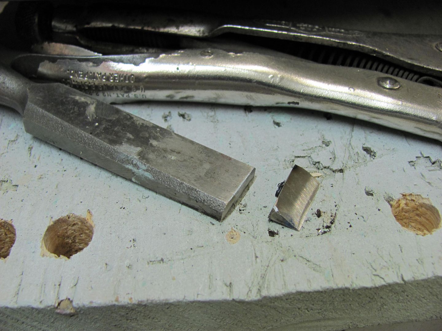
We'll start off by finding a pair of vise grips suitable for the job, which in this case means the jaw serrations are starting to wear and round off and won't grip much of anything else. Finish what has started by removing the serrations to produce a nice flat jaw on the bottom, and cut the top one off at about 30 degrees from its original position.


Picture001-3.jpg


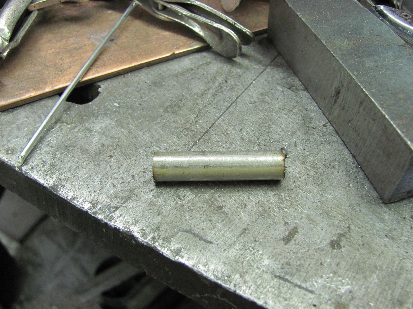
I had some extra long shouldered 3/8 bolts, perfect round stock for the job. Three of them were cut off to 1-1/2" length.


Picture003-3.jpg


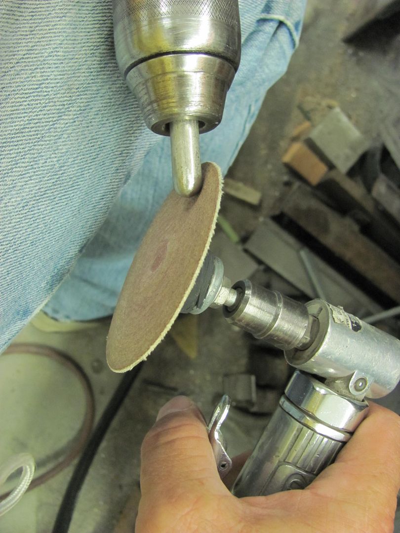
Here's my economy model lathe made by Dewalt...


Picture004-3.jpg


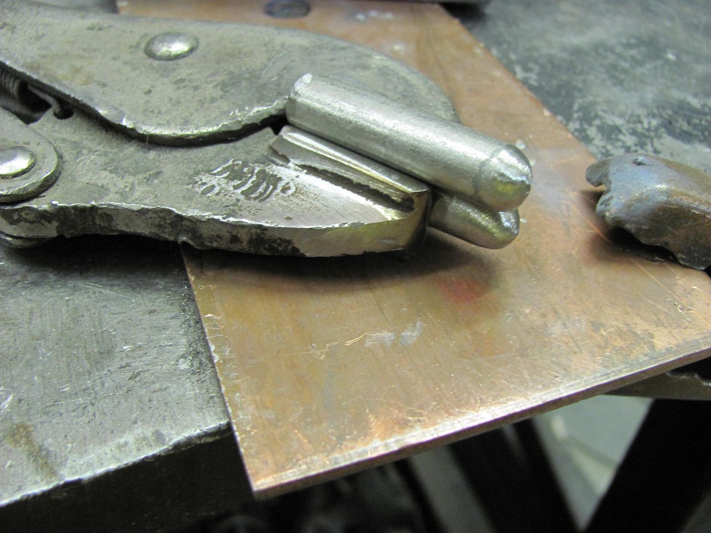
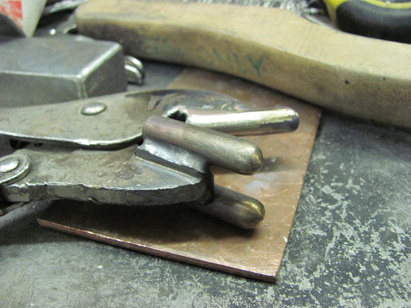
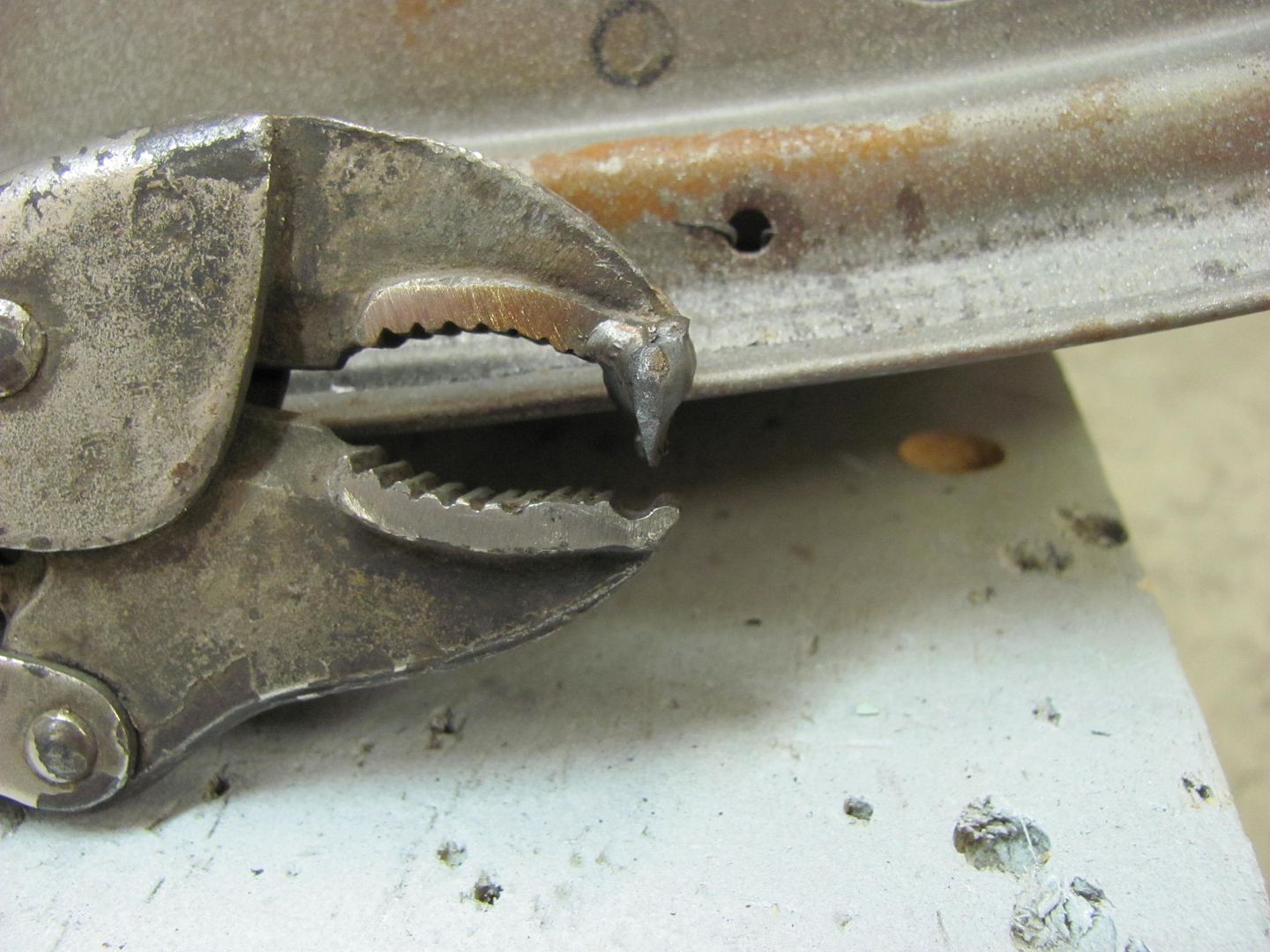
To set the spacing for the "fingers" the first is clamped in the vise grip jaw, centered.


Picture007-2.jpg


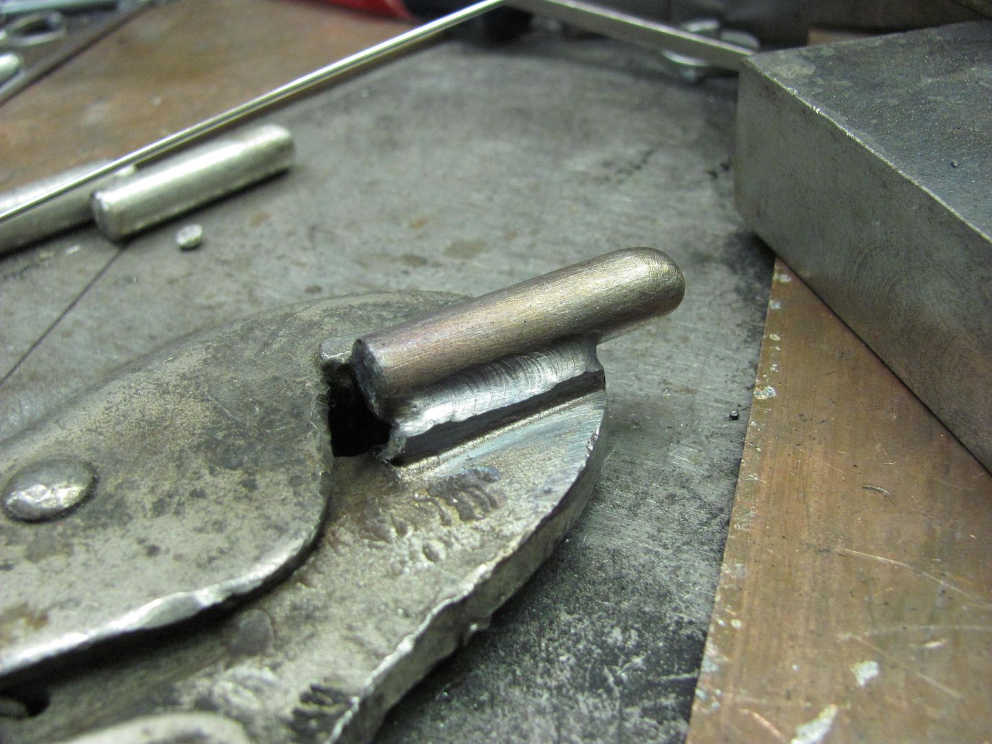
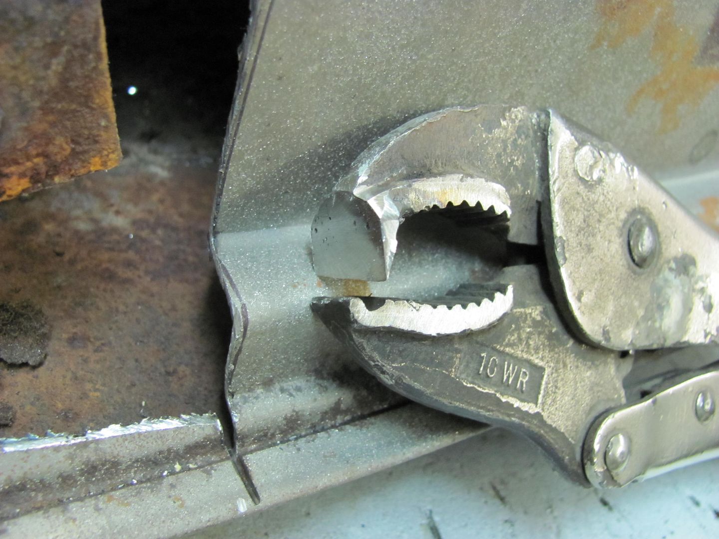
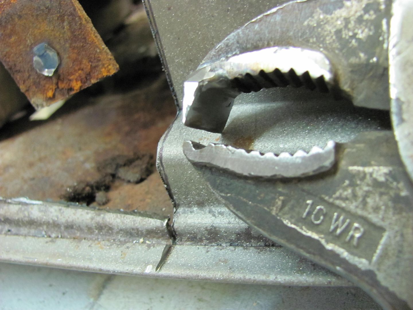
The outer is placed next to it and then welded down the outside, center finger removed, and then welded down inside. Here we should leave a slight gap of your sheet metal thickness to prevent any binding, which will allow a deeper tuck.


Picture008-2.jpg


Picture009-2.jpg


Picture010-2.jpg


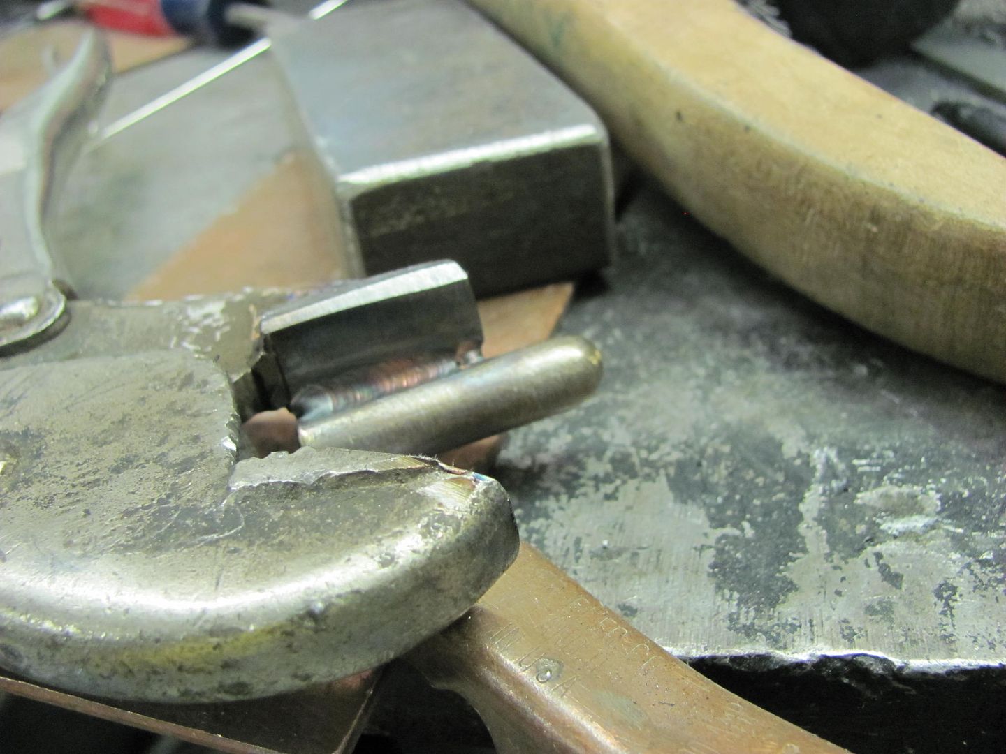
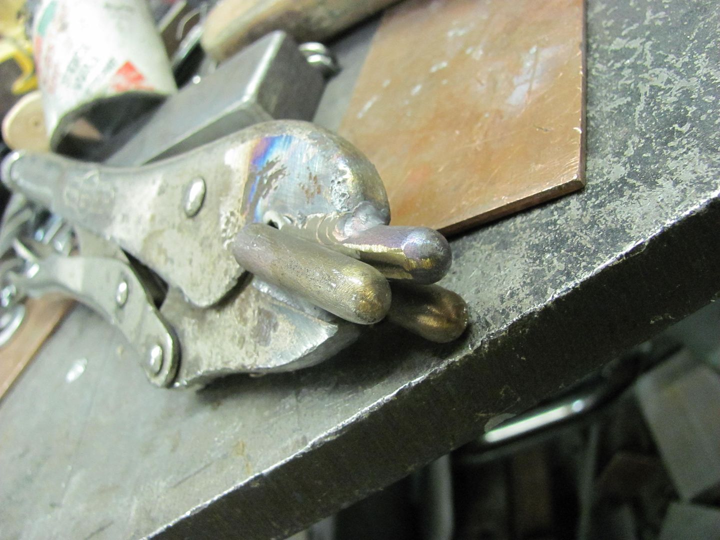
Repeat for opposite side, then weld center finger.


Picture011-2.jpg


Picture012-2.jpg


Note in the above picture the 30 degree cut of the upper jaw positions the center finger at an angle compared to the bottom fingers. It is this angle that will help to form the tuck's shape.


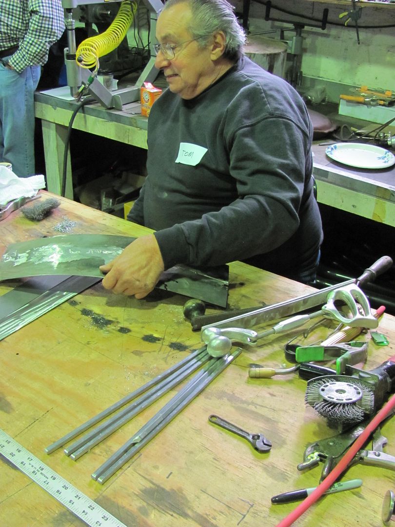
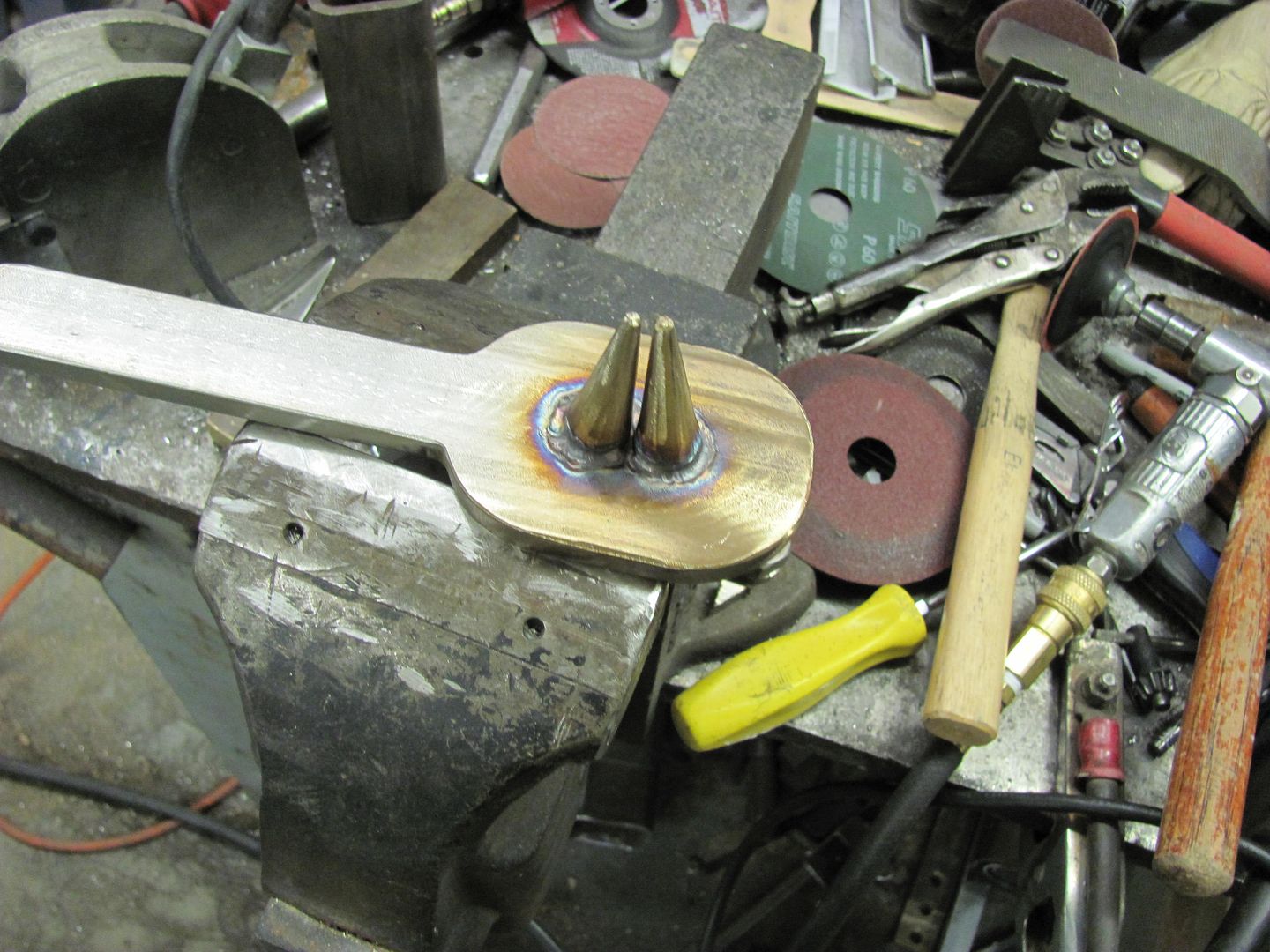
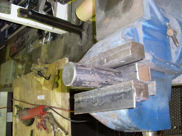
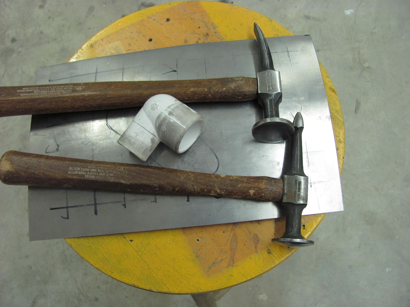
Of course I took my favorite anvil along to the meet, here clamped in the vise..


SL371399.jpg


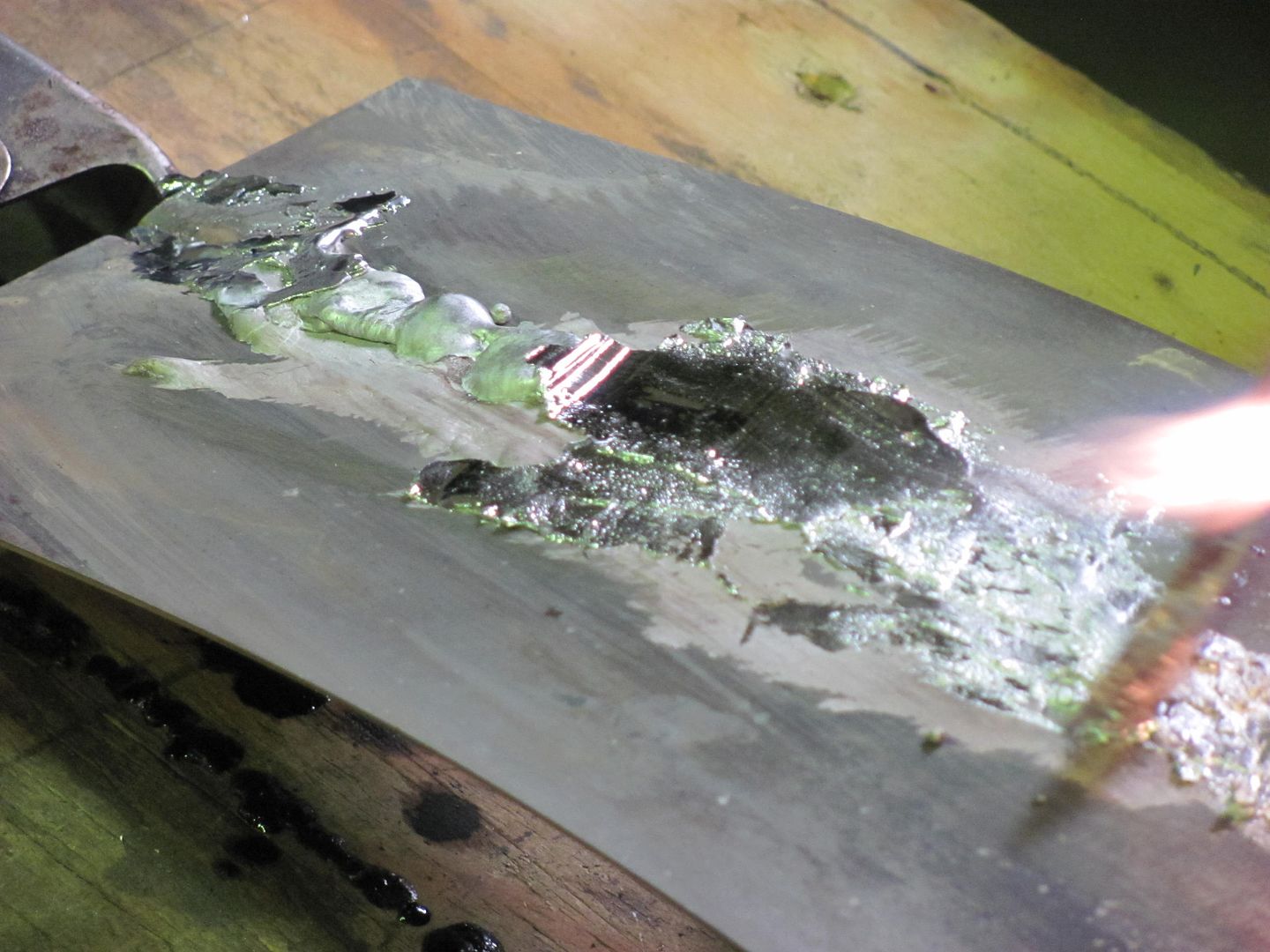
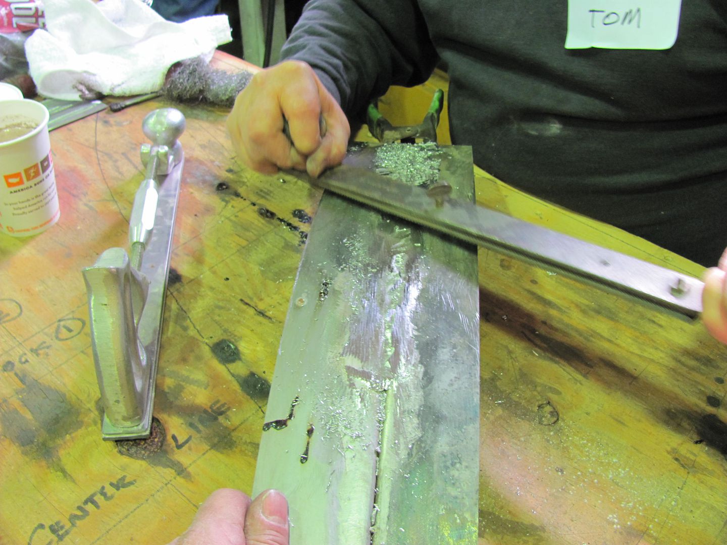
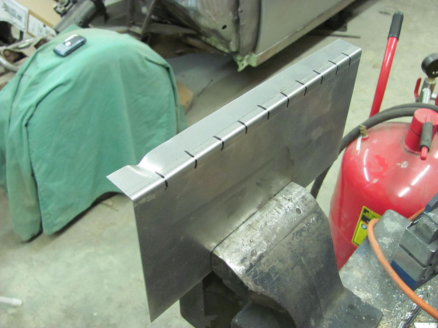
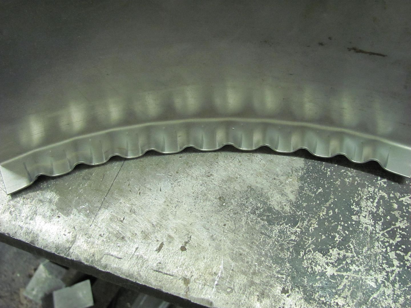
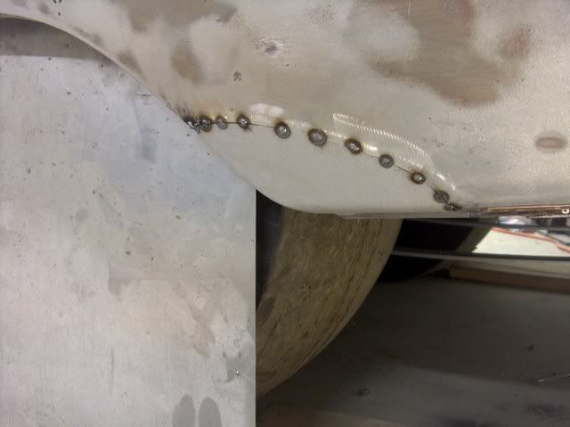
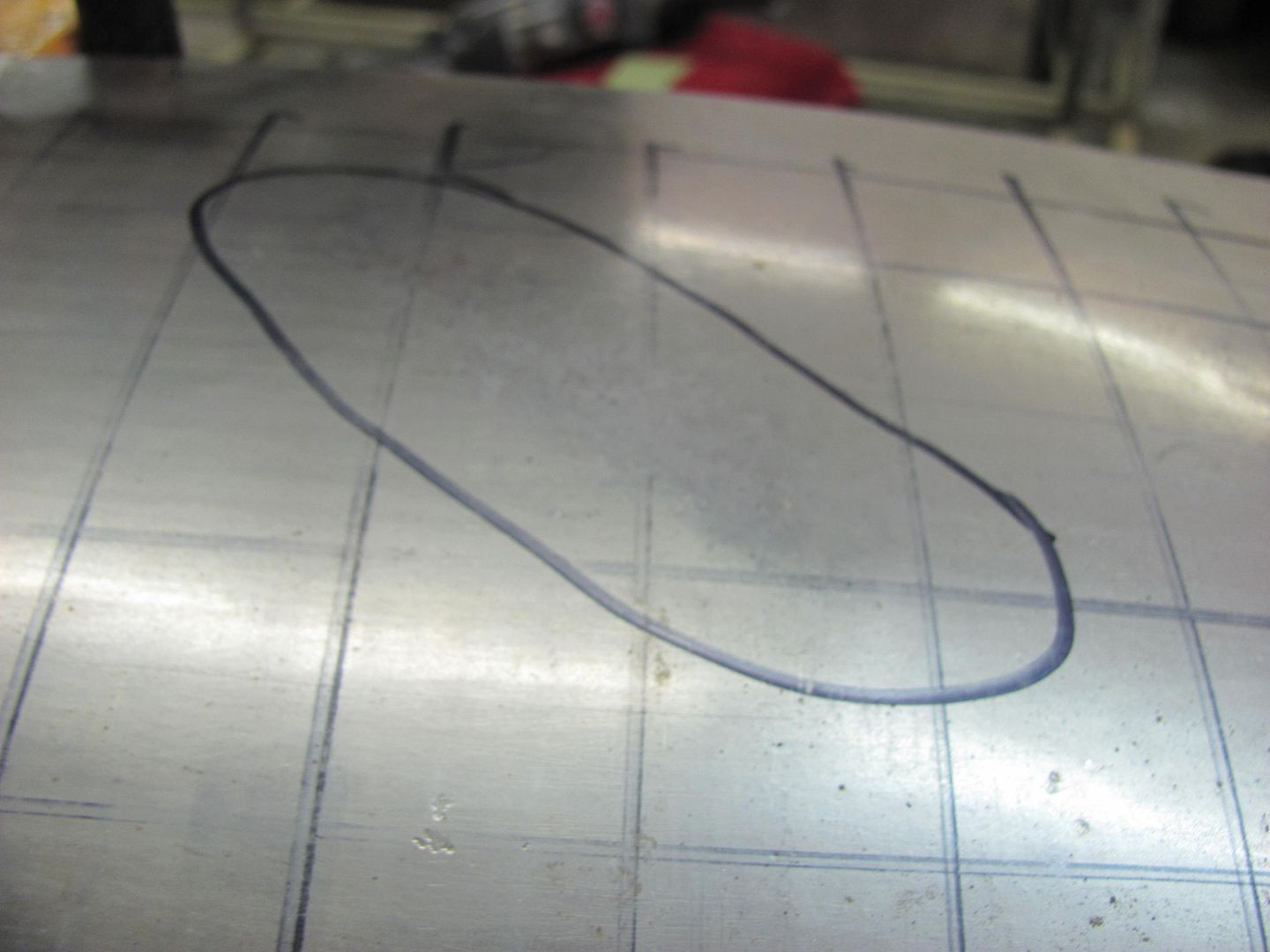
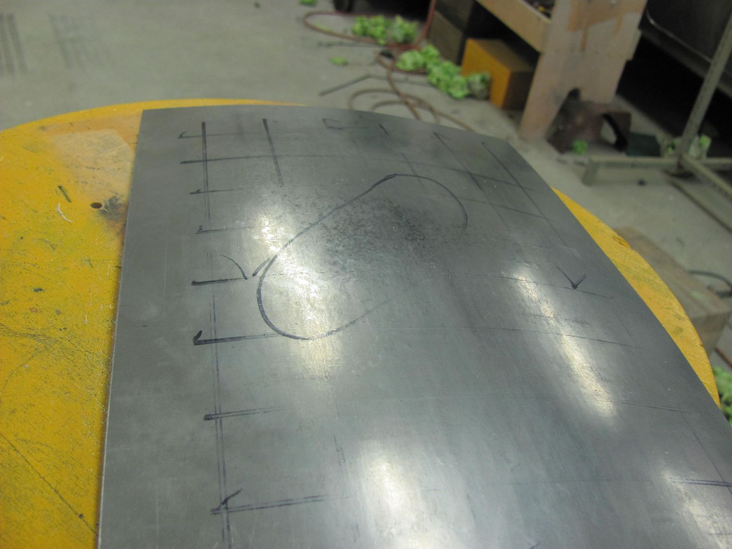
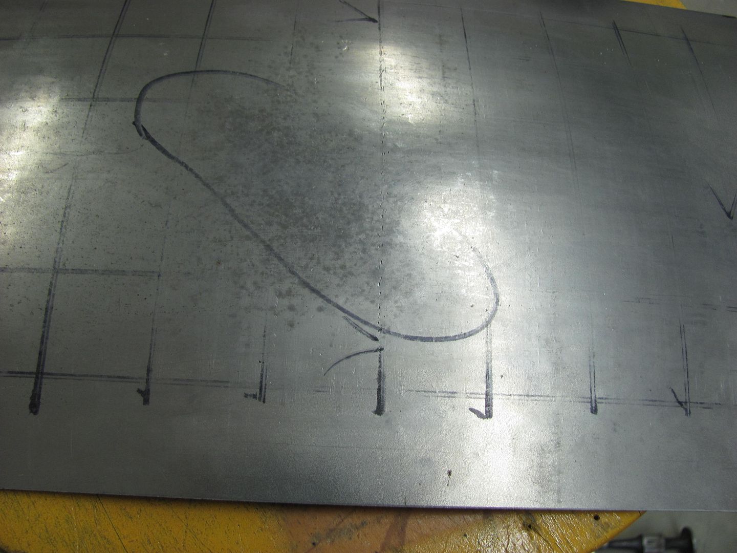
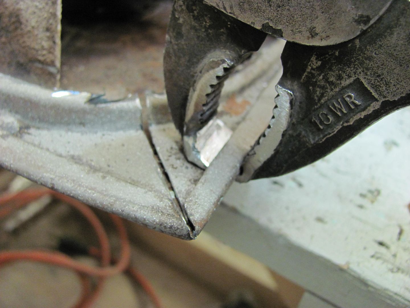
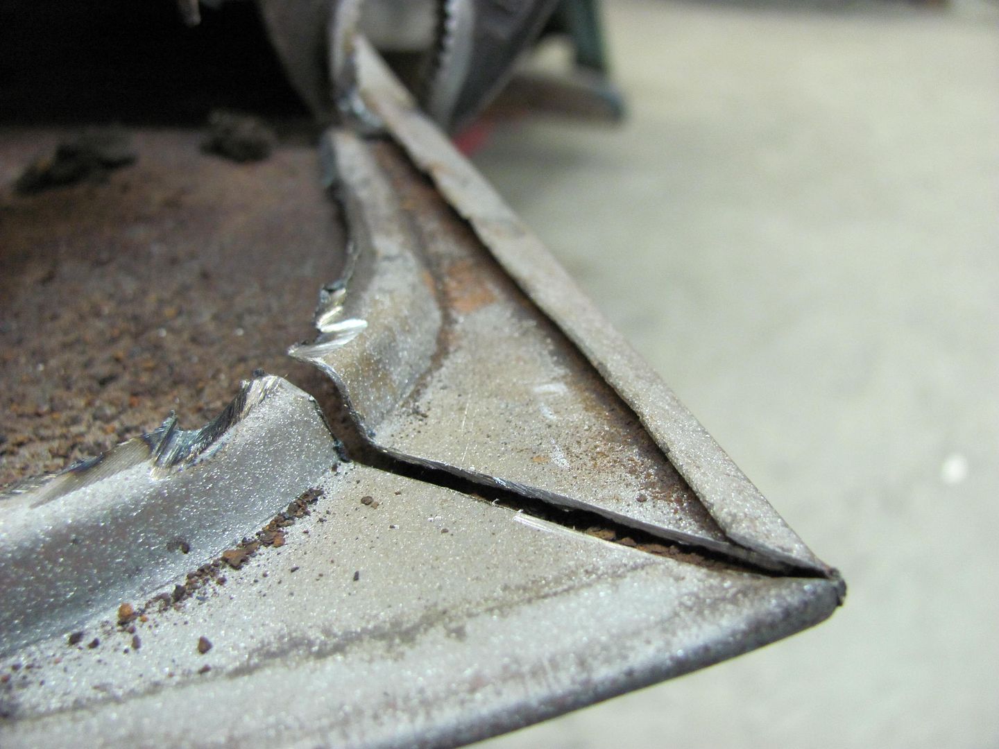
Again our object in this case is consistency, so equally spaced marks are placed on the flange, identical tucks made at each mark, and you can see the consistent radius along the panel.

Picture014-2.jpg


Picture016-1.jpg


Picture018-1.jpg


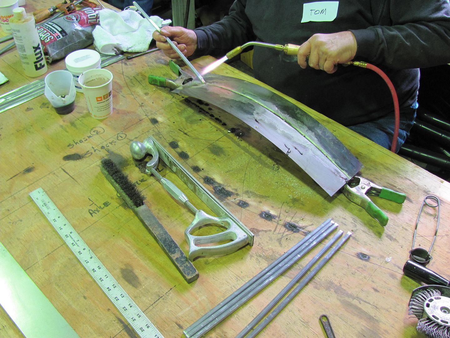
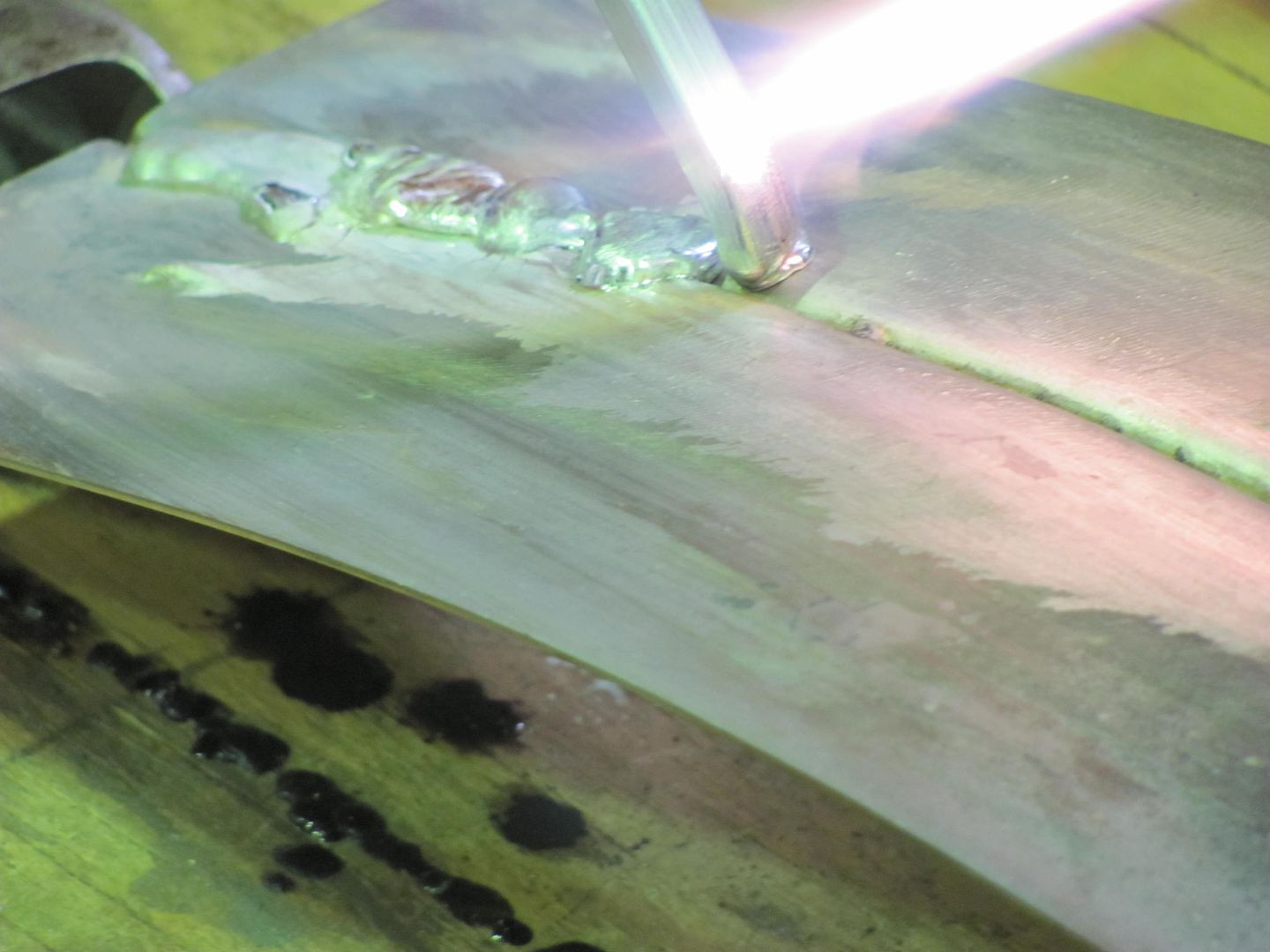
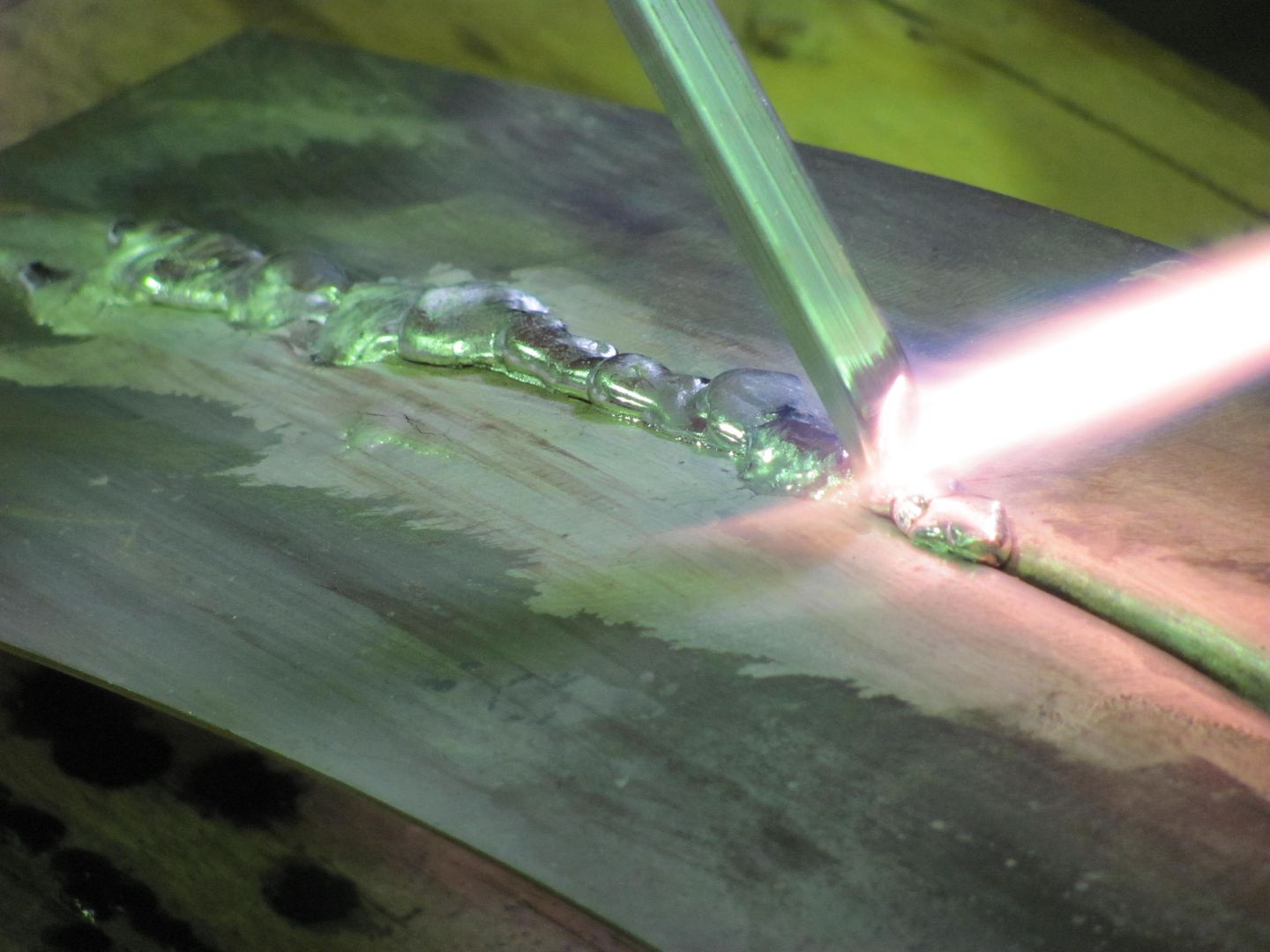
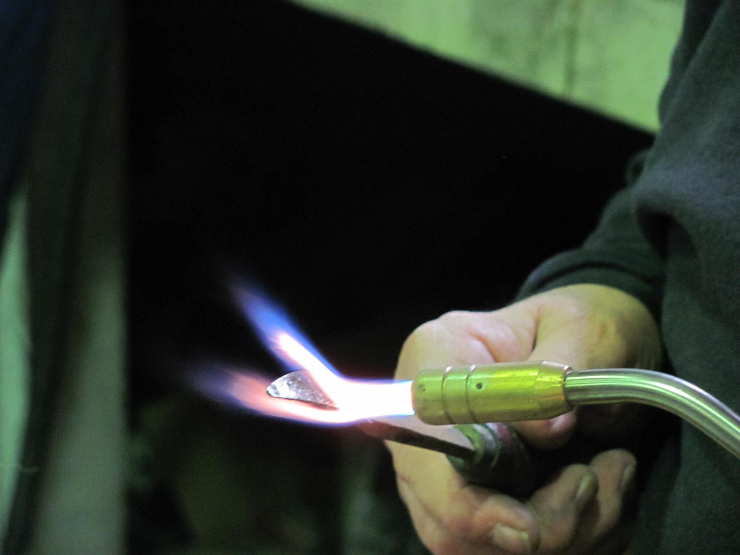
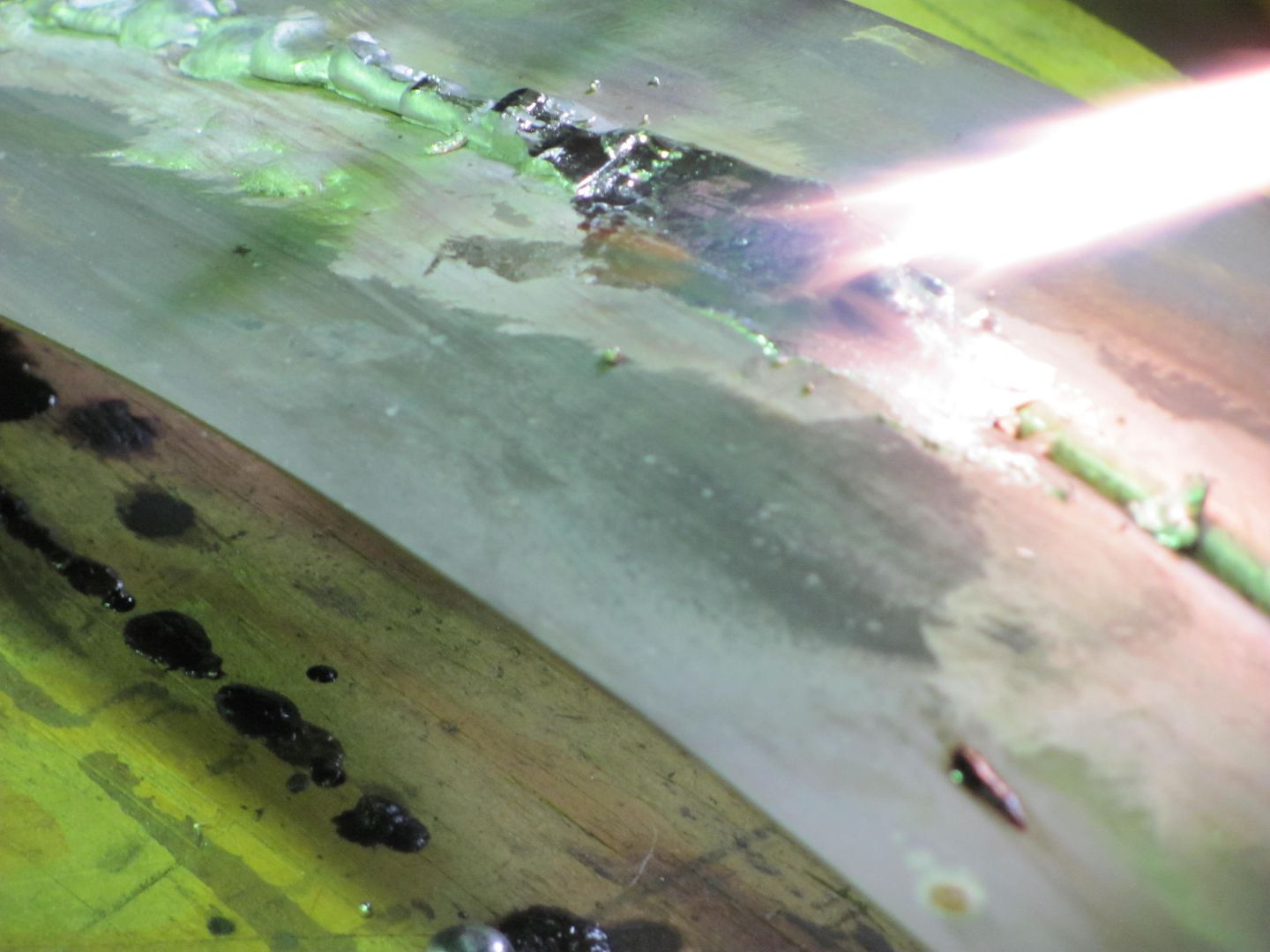
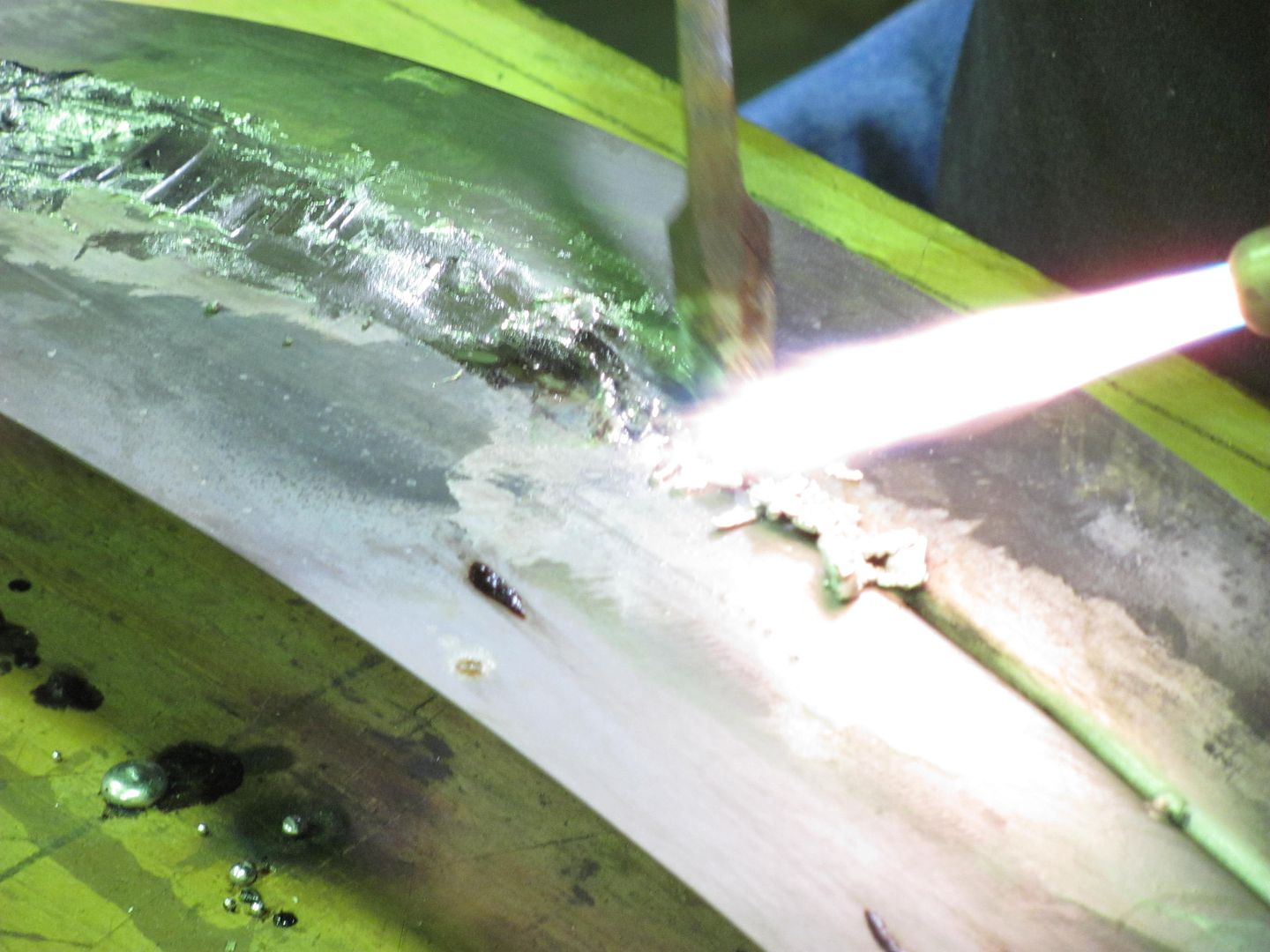
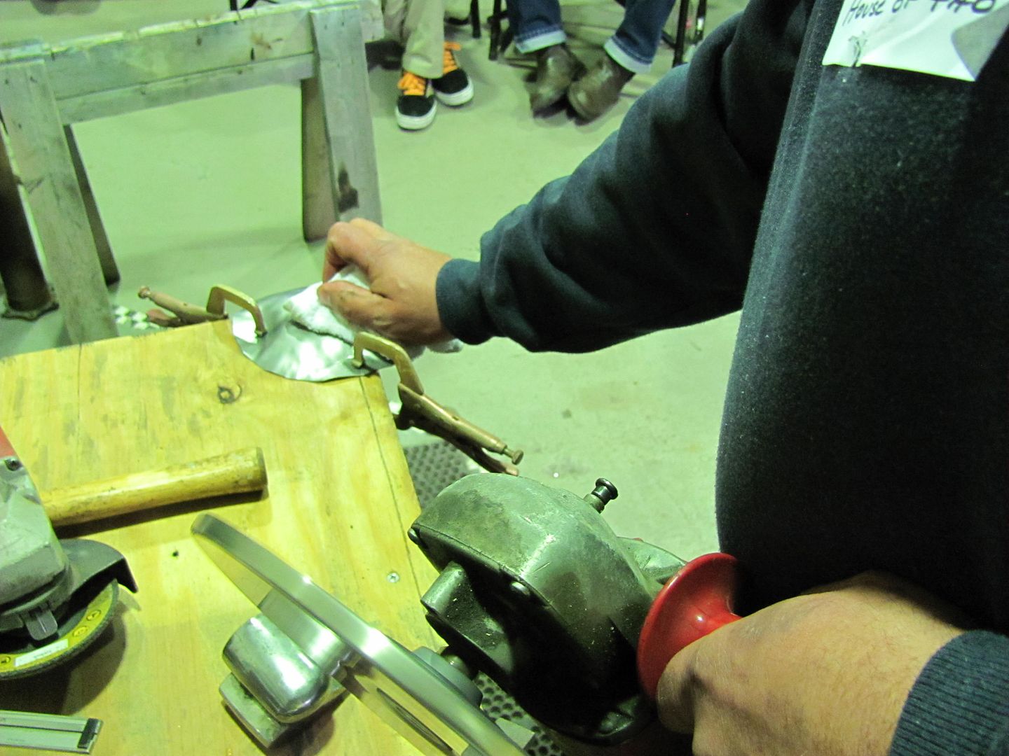
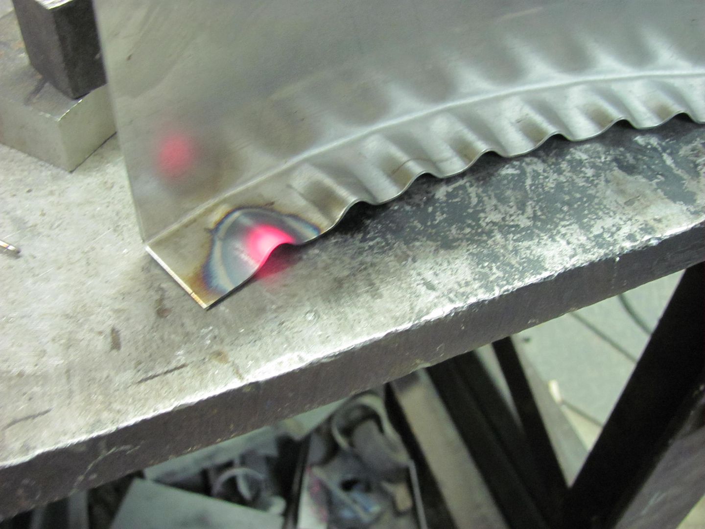
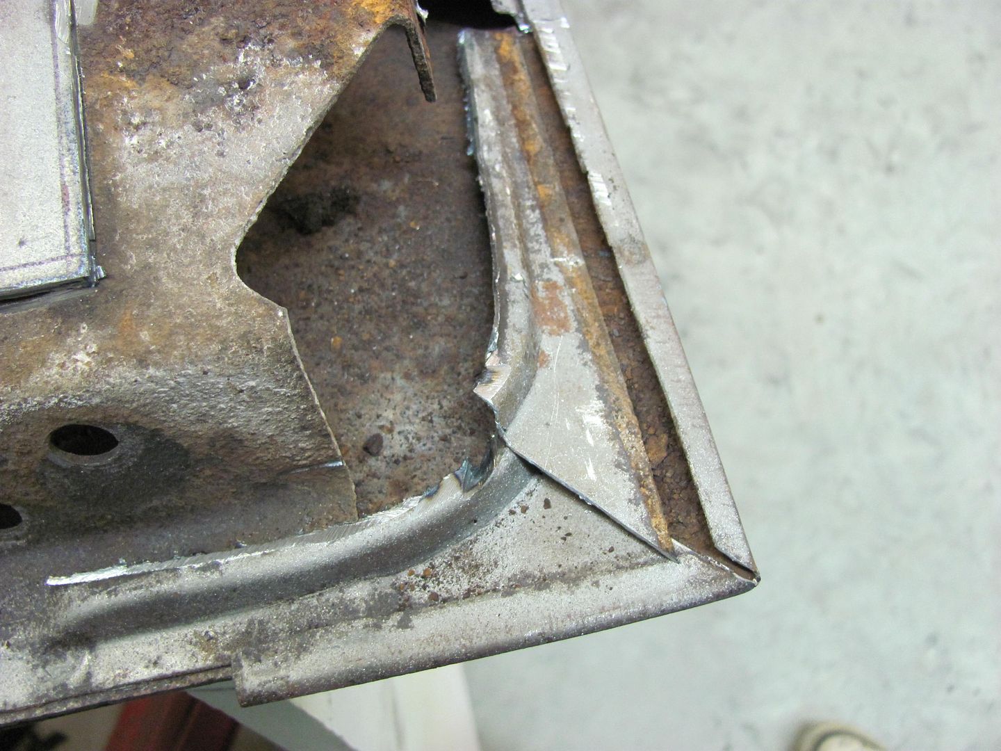
I use a O/A torch to heat the tucks prior to hammering them flat. Others prefer to not use heat, and can capture the tuck and flatten it very effectively without it. I am still working on this proficiency, so in the meantime, I use heat. We're looking for something like this, prior to hammering.

Picture021-1.jpg


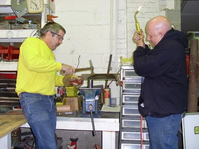
Here OJ assists with torch duties...

SL371372.jpg


Another point to mention is that the hammering action tends to also spread the tuck back apart if not captured effectively. Where the picture above doesn't show it well, a good means of overcoming this would be to clamp a strap of metal across the ends of the newly formed radius prior to hammering, similar to this:

Tucks-1.png


Then the hammering force will be more effective in flattening the tuck back into itself.

SL371373.jpg


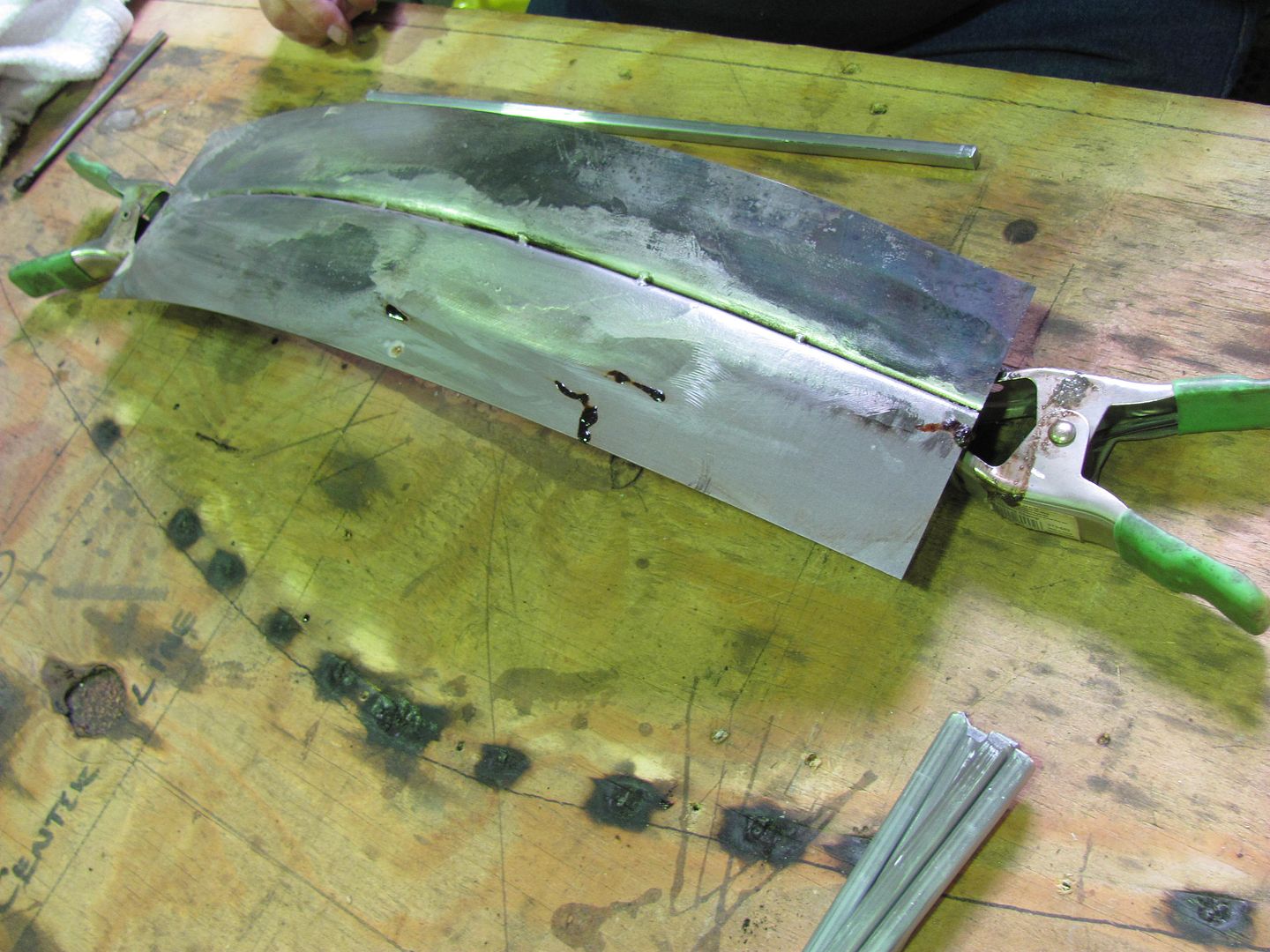
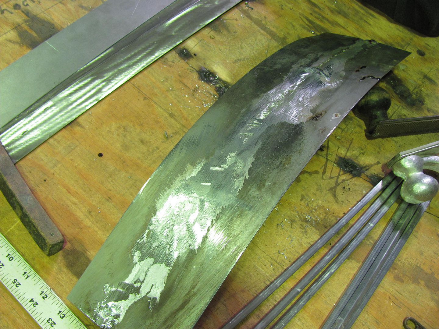
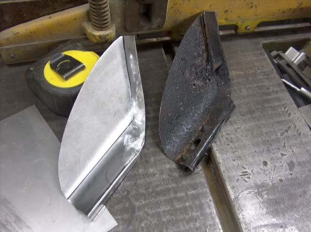
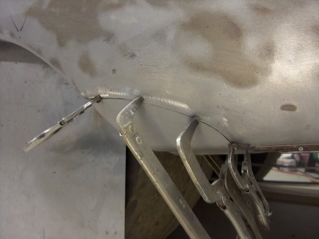
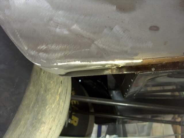
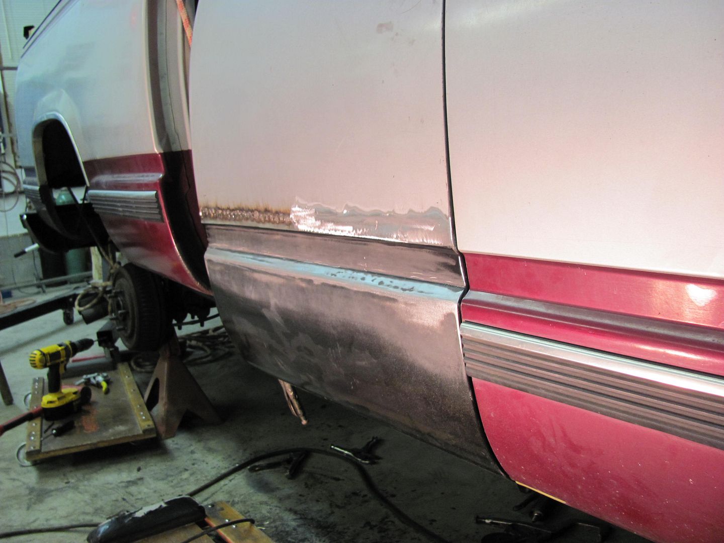
Once each piece was completed separately, the flanges were aligned back to back and the two pieces tacked together. Each had an identical radius, for a good fit. Consistency pays off!

SL371374.jpg
 
Last edited:
To avoid these ads, REGISTER NOW!

FJ45Cruiser

Well-known member
Joined
Nov 13, 2008
Messages
72
Location
Whitinsville, MA
I've found reading through this thread very helpful and am ready to start my welding. For some reason this flanged cap was rivited into the top of my 77 FJ45 Land Cruiser top.
attachment.php


I drilled out the rivits and cut the area out with a Harbor Freight body saw. I don't think it really liked cutting through 16ga. sheet.

attachment.php


I took some duct tape and put it over the hole and was able to see a pattern and cut out a piece of metal from an old hood I had. I cut it a little larger and then used a scribe to mark what I needed to clean up further. Here is how it turned out.

attachment.php


Does it looks like it fits to tight?
 

MonkeyNutZ

New member
Joined
Nov 27, 2010
Messages
2
I've got a lot of bodywork and and about a dozen patches to make and weld in for my 1973 Opel GT restoration. I think I've read over this thread pretty thoroughly but I don't see an answer to my question: What can I do to avoid warpage and shrinking in places I can't planish the welds (for lack of access) in addition to spacing out the distance and time between tacks?
 

MP&C

Well-known member
Joined
Oct 21, 2009
Messages
4,396
Location
Leonardtown, MD
Any thoughts on the use of heat sponge to minimize the distortion when **** welding patch panels?
(link removed)


I've never tried one, but think you'll find the area in the immediate vicinity of the weld is going to shrink, regardless of what you do around it. Throw some water or blow air across it to cool it more quickly, and it serves no other purpose than to make the weld more brittle. IMO, unless you're trying to keep heat away from something that would burn, i.e.: rubber weatherstripping, paint, vinyl top, etc, then weld what you're going to weld, let it cool naturally, and deal with the distortion from shrinking after the fact.


I've found reading through this thread very helpful and am ready to start my welding. For some reason this flanged cap was rivited into the top of my 77 FJ45 Land Cruiser top.
attachment.php


I drilled out the rivits and cut the area out with a Harbor Freight body saw. I don't think it really liked cutting through 16ga. sheet.

attachment.php


I took some duct tape and put it over the hole and was able to see a pattern and cut out a piece of metal from an old hood I had. I cut it a little larger and then used a scribe to mark what I needed to clean up further. Here is how it turned out.

attachment.php


Does it looks like it fits to tight?


I think you did a nice job cutting it out; you want it to fit tightly. I would suggest trying to find another piece of 16 ga to match the surrounding metal, as varying thicknesses may react (shrink) at different rates, and besides, any attempt to hammer and dolly any distortion from shrinking will tend to bump the panels around if they are not the same thickness, possibly causing a bit more distortion during the hammering process.


I've got a lot of bodywork and and about a dozen patches to make and weld in for my 1973 Opel GT restoration. I think I've read over this thread pretty thoroughly but I don't see an answer to my question: What can I do to avoid warpage and shrinking in places I can't planish the welds (for lack of access) in addition to spacing out the distance and time between tacks?


This answer will depend on each of different conditions that exist in different areas on the car. No access to the back for hammer and dolly work, can you make a home-made dolly with a long arm/rod to be able to hold in a remote location? Can you cut an access hole in an inside panel to provide room for a dolly in order to straighten the outside panel, and then weld the access hole closed again?

Any welding operation is going to cause a certain amount of shrinking. Welding in a square-ish repair panel (for example) toward the bottom of a fender will induce a certain amount of shrinking and distortion, in four directions. By extending your patch to the wheel opening, and all the way to the bottom of the fender, you eliminate two weld seams, and half as much shrinking. If you can replace the complete lower fender from wheel opening to door opening, to the bottom, now you are down to one weld seam, and all the forces are pulling in a similar direction (as opposed to what you see with two intersecting welds) and the distortion should be less.

If you can trim your joints to zero gaps such that a no-filler weld can be performed (TIG or O/A), then you should have about as small a HAZ as possible, and as consistent in width as possible, for less distortion. To explain this further, various starting and stopping in your weld will cause inconsistent width of the HAZ, along with the shrinking effects that come with it. This may lead to a "wavy" distortion. Consistent heat, consistent speed, without stopping, in performing this weld will help to keep the HAZ, and all the other conditional reactions consistent, for less distortion. Having said all that, this example was for use with a TIG or O/A. Most enthusiasts will be using a MIG welder (as that's what they have) which is not very compatible with a full pass weld when dealing with sheetmetal. But you can still apply the same principles of consistency in using a MIG and "dot" welding. Single dots, skip around, use same overlap, same size dots (elapsed time of trigger pull) etc. This won't make the weld as nice as the fusion weld above, but it will help with consistency. And the biggest thing is to practice on some scrap pieces the same guage as you'll be working with to insure your welder is set up correctly for a full penetration weld. It's hard to be consistent if you're putting in the patches and still fiddling with welder settings, (practicing on the good stuff).
 

metalbasher

Member
Joined
Mar 6, 2011
Messages
14
Location
Alabama
146d4d8e.jpg


I use about a 120 or so grit 3" sanding disc to completely flatten the end of the drill bit (I use a letter A for all my plug welds, works good with the heat setting I am at), You end up with what looks somewhat like a figure 8. With all that flat surface, it would be more difficult to remove paint, so on the back side of the leading edge of the cut, using the sanding disc again, and angled "relief" is formed in each side. This now leaves about a 1/16" wide flat straight across, as you can see above, which works much better to remove the paint. The EP I'm using is KP-2CF from House of Kolor.

I tried this out this past weekend on my QT panel replacement. It worked like a champ. You have great metal workng skills. Keep the good stuff coming.
 

Attachments

  • fastbackleftside 029.jpg
    fastbackleftside 029.jpg
    115.9 KB · Views: 227
  • fastbackleftside 044.jpg
    fastbackleftside 044.jpg
    121.3 KB · Views: 235

Llano88

New member
Joined
Jun 22, 2011
Messages
3
Location
Annapolis, MD
Robert, Can you go through the process of planishing the welds for me? I apologize if you've already been through explaining this. If so, just point me where I can read about it. Amazing work here. I'm about to put some patching into my Mustang and I think any knowledge I could glean from you would be immensely helpful.

PS I see you're in Leonardtown. That's only about 70 miles south of me.
 

Llano88

New member
Joined
Jun 22, 2011
Messages
3
Location
Annapolis, MD
Well, I have some firewall patches to do, cowl panel, toe boards, fenders will need patches, wheel wells. The normal rust spots on a car from the 60s.
 

MP&C

Well-known member
Joined
Oct 21, 2009
Messages
4,396
Location
Leonardtown, MD
If you haven't read this entire thread yet, try starting with post 155 and 156. Should help to explain some of the planishing. For much of the "hidden" patches, you can many times get by with leaving them as is because no one will normally see them, but I like to use these as "practice samples" for when it does count. You can watch the metal, see how it reacts to heat from welding, see how the planishing efforts will correct the distortion. Then you will be better prepared for the patches you can see, like the bottoms of the fender. See post 3 on page one, it will show a bit of planishing the weld "dots". As explained in the post above (response to Monkeynutz re: Opel GT), if you can find/fabricate a patch that goes straight across the entire bottom of the fender and not just a corner, you will have the shrinking forces only pulling toward the one weld, for what may prove to be an easier job of planishing out the distortion. A corner patch will have two perpendicular welds, where the shrinking forces on the inside corner tends to add together and will make planishing that area more of a chore. That's why if you are forced to use inside corners on your patches, most people will put a wide sweeping radius instead of a sharp 90, to minimize those "doubling" effects. This is shown on post 93, on the Biscayne fender patch. I'd say if I had to do that one over again, it would have been a better job if we had just gone straight across the entire bottom with the patch we made.
 
Last edited:

Llano88

New member
Joined
Jun 22, 2011
Messages
3
Location
Annapolis, MD
I'm working my way through it as there is a TON of useful stuff in here. I'm on post 73 right now. Good point about practicing on stuff no one will see. I'll be sure to do that.
 

gelierb

Well-known member
Joined
Nov 16, 2010
Messages
52
Location
Redwood City, CA
That's why if you are forced to use inside corners on your patches, most people will put a wide sweeping radius instead of a sharp 90, to minimize those "doubling" effects.

Robert,

Should I be worried about putting a larger radius instead of the 90 degree corners on a simple patch like this?

Thanks,
Gus

seat_support_patch1.jpg


seat_support_patch3.jpg
 
Last edited:

MP&C

Well-known member
Joined
Oct 21, 2009
Messages
4,396
Location
Leonardtown, MD
I'd be more worried about it on outer panels to minimize any distortion. With the creases in your floor patch they should help to keep things in check.
 

edboyles

Well-known member
Joined
Jul 30, 2005
Messages
176
Location
DFW, TX
(continued)

Here we have typical rust damage due to dirt and water collection in the nooks and crannies.


Picture227.jpg


Here I have forced the issue. We need to make a repair panel..


Picture228.jpg


Rough layout and forming the repair


Picture229.jpg


Picture231.jpg


Slight bends, shrink the corner, repeat


Picture234.jpg


Picture236.jpg


Picture237.jpg


Picture238.jpg


Fitment and tack welding


Picture240.jpg


Picture242.jpg


Here I would stop and planish the weld dots with a hammer and dolly, just like the post I did on page one, lower fender. This helps to negate the effects of shrinking from the welding process. Then grind down these dots to just above panel surface, so they will be out of the way for planishing the next set of dots. (use 1/16 wide cut off wheel to grind as described in previous post about grinding welds) Now weld the next dots, overlapping the originals by about 1/3 to 1/2 diameter of the dots. Continue the dot welding, planishing, and grinding, and repeat until finished. Then clean up the remainder with about a 60 or 80 grit sanding disc in your 3" sander.


Picture243.jpg


Picture246.jpg


I hope this helps, good luck on the Miata!

Outstanding! Damn.......... you are good!
 

MP&C

Well-known member
Joined
Oct 21, 2009
Messages
4,396
Location
Leonardtown, MD
Just to add to this thread, where it may not apply to welding it may help out in dent repairs....


One of the guys over on the metal shaping web sites has a neat tool he sells called a donut dolly. It works more proficiently in off-dolly shrinking a crowned panel because it supports the bottom side in more than one spot (around the perimeter) as the panel is bumped from the top in the center of the donut dolly. This would seem to be useful in body repair, especially to address high spots found after blocking primer where heat would not be as feasible.

A few days ago, someone on another forum asked for advice in removing an outward roof dent. I suggested a low-buck alternative to the donut dolly, simply using a PVC pipe fitting. Where it may not work as aggressively as the donut dolly which has more mass, sometimes slower is better, especially when trying something new. I just today got around to trying this process in the shop, and rather than use the roof of something sitting here, we will use a piece of 18 ga CRS to simulate a roof.

Grid layout for the Wheeling Machine, and completed "sample" roof...


Picture112.jpg


Picture113.jpg


The first order of business should be to make some profile templates. In the case of an actual dented roof, use the opposite, undamaged side. This will allow you to check your progress as you go, and easily find the remaining high spots.


Picture114.jpg


Picture115.jpg


Using a crowned body hammer, a "dent" will be added from the back side, crossing both of our template areas.


Picture118.jpg


With the dent added:


Picture119.jpg


Picture120.jpg


Picture121.jpg


I chose to use a PVC elbow, it had two different sized ends for two tools in one. As with any body tool, they should be free of any burrs that may mar the metal surface. I also added a slight radius to the edges...


Picture123.jpg


Picture124-1.jpg


Holding the dolly against the bottom of the panel, you can see that due to the dents it only touches the panel at the red arrows. Based on off-dolly principle, the shrink would occur more prominently in the direction of the red arrows. If we needed to shrink in the direction of the green arrows, we would need to relieve two sides of the dolly to allow a contact pattern in the direction of the green arrows. This makes it especially important to check your progress with the templates, not only to find the high spots but more importantly to see which direction requires shrinking to insure the contact pattern will provide the neccessary shrink.


Picture142-1.jpg


Here are the tools we will use today:


Picture140-1.jpg


After some off-dolly bumping:


Picture133-1.jpg


Check with the templates


Picture130-1.jpg


Picture131-1.jpg


Progress....these are light taps only with the hammer. We just want to bring down the high spots, not create craters.


Picture136-1.jpg


Picture137-1.jpg


Here's where I finished up...


Picture134-1.jpg


Picture135-1.jpg


I have a little over an hour in making the panel, denting, and removing the dent. Where I still could have gone a bit more, it was about to a point where high build primer should have masked any remaining imperfections. This dent removal could also have been accomplished with heat shrinking using an O/A torch, etc, but for those times where you may not wish to use heat and want another option, this seems to work well. I think with using the donut dolly and it's heftier mass, one could shave some additional time off the repair.
 

afazz

Well-known member
Joined
Nov 25, 2007
Messages
860
Location
Pittsburgh, PA
Yes thank you, very nice work! What is the face radius on those hammers? I can see at least one isn't stock anymore.
 

MP&C

Well-known member
Joined
Oct 21, 2009
Messages
4,396
Location
Leonardtown, MD
Both are snap-on body hammers, one is a low crown (almost flat....the top one) the other has a crown to it. They both are as they came on the truck other than me polishing the surface a bit.
 

afazz

Well-known member
Joined
Nov 25, 2007
Messages
860
Location
Pittsburgh, PA
Interesting, I have two versions of that pick hammer (BF603 sharp and BF630 blunt) and both have a low crown face. They must have changed through the years as both of mine are rather new. Thanks for the info!
 
To avoid these ads, REGISTER NOW!
Top Bottom