To avoid these ads, REGISTER NOW!

Welding in patch panels

MP&C

Well-known member
Joined
Oct 21, 2009
Messages
4,396
Location
Leonardtown, MD
I had some questions on another forum I had this posted on, and felt the discussion would add clarification.


72novaproject said:
Help me understand this Robert.

Would the conventional method to remove that dent be to use something like a heel dolly and move it around the circumference of the dent while tapping the high spot in an off-dolly operation? I assume you would then need to heat shrink the remaining high crown.

Is the difference here that your method spans across two sides and still allows for an off-dolly operation? Why couldn’t you span the dent with a large low crown dolly or would that end up being an on-dolly operation?

About the time I think I understand this I get thrown a curve ball.

Steve

First off, lets clarify the on and off dolly again. On-dolly:


OnDolly.png


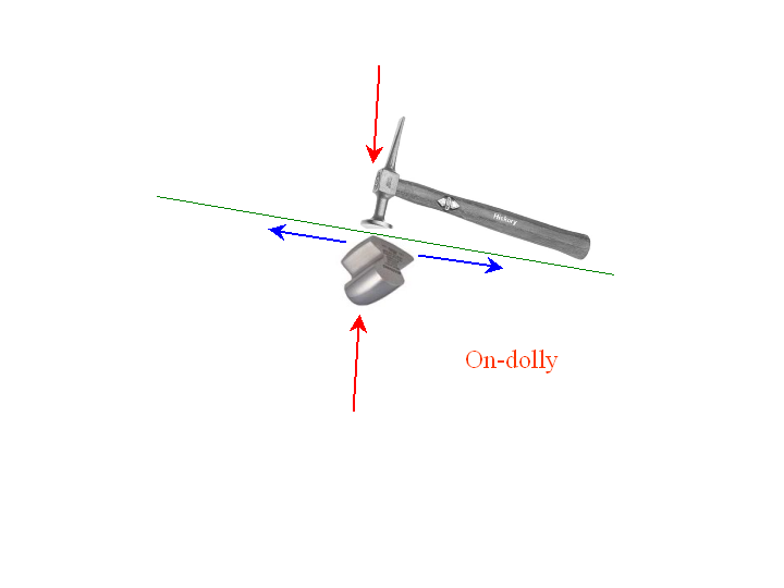
As the hammer stikes the panel with the dolly held directly beneath, the forces come together (red arrows) and the panel is compressed between the two. With nowhere else to go, the metal is forced outward (blue arrows) in the form of a stretch.


Off-Dolly:


OffDolly.png


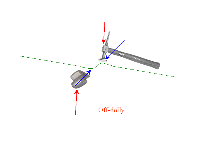
This time as the hammer strikes the apex of the dent from above, and the dolly rests against the one from below, their offsetting positions will cause the resulting forces in the direction of the blue arrows, forcing the metal back into itself, or causing a shrink.


Seldom is the case where we have a one-sided dent. Typically with an off-dolly scenario in fixing a dent, it is exactly as you describe, using off dolly and working around the perimeter of the dent to bring things back where they were.

As you surmised, spanning the two sides of the dent, we can off-dolly with more effectiveness, as the forces we are now introducing are more concentrated, or "Off-Dolly on steroids". But lets back up a second and look at the forces at work when a dent forms.


OffDolly1.png


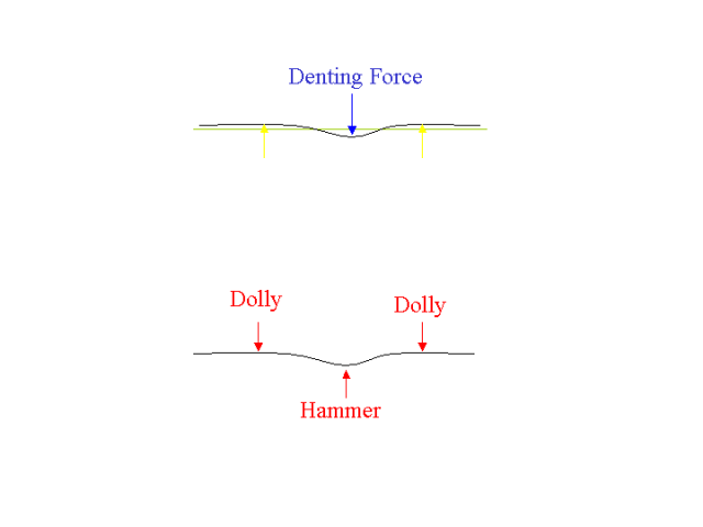
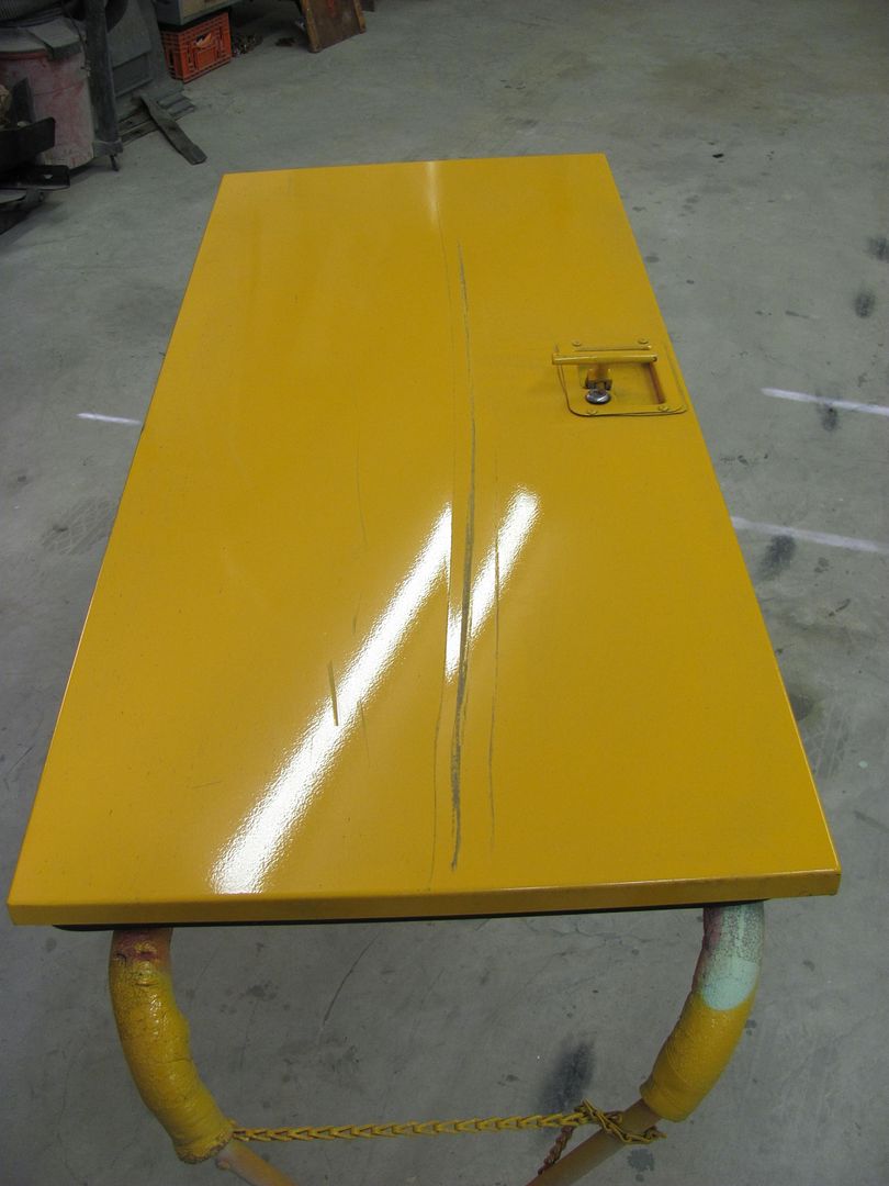
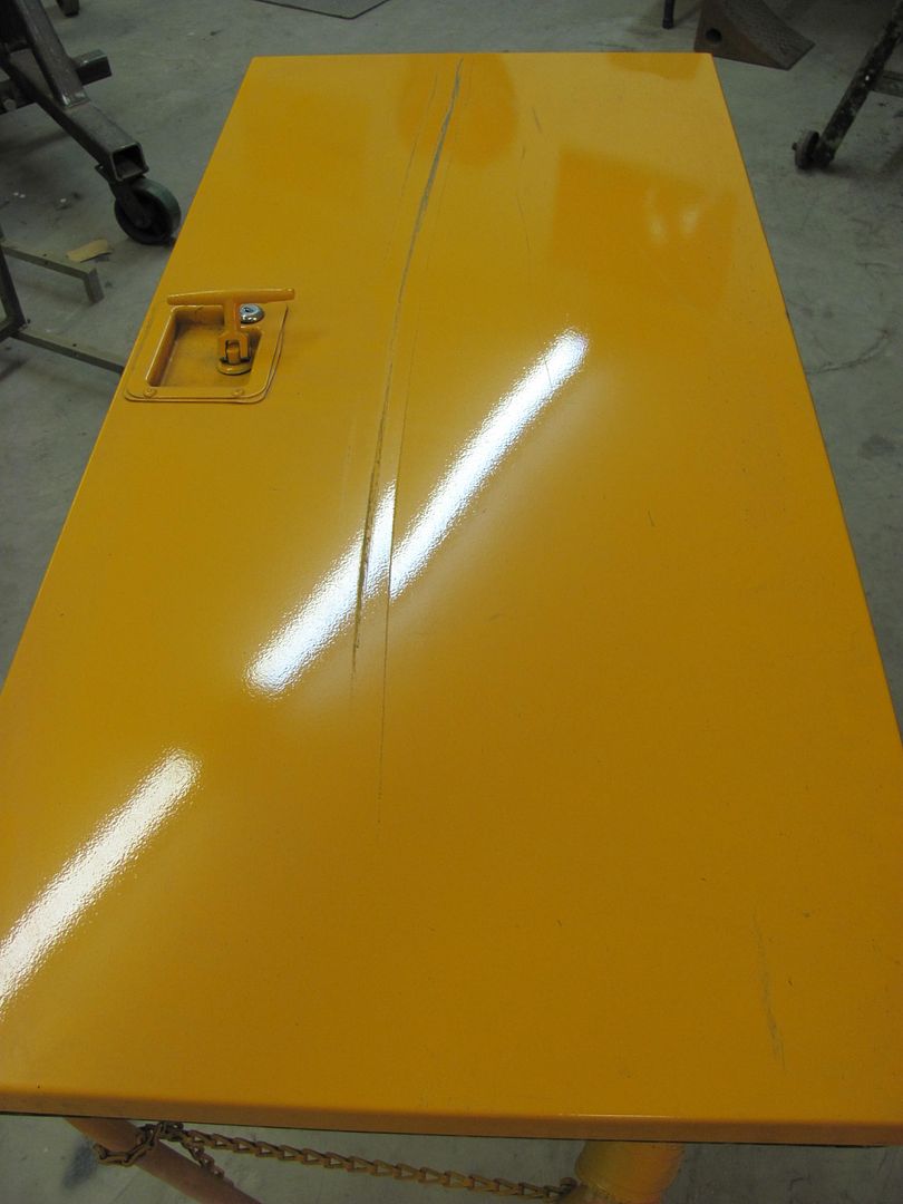
As an outside force is applied to the door of your new car (blue arrow), the direct reaction is a stretching of the metal, causing it to cave in. But we also have an indirect reaction in this stretching as the panel "springs back" slightly and you'll now notice a slight bulge or high spot around the perimeter of the dent (yellow arrows) This is why effective dent removal will include working both sides of the panel.

Moving down to the next view, we can see how an off-dolly scenario which supports both sides of the dent should prove to be more effective than the "one side at a time" method shown above in the second picture. Getting back to your suggestion of using a low crown dolly to span the dent, this would work up until the point the dolly made contact with the panel from the hammer striking the other side, as now we are stretching again. And just like the indirect forces in play when the dent was formed, there is also a small amount of springback when hammering out the dent. So to accomodate these forces, a hollow dolly would better fit the bill. Now on to the the problems associated with the hollow dolly:


OffDolly2.png


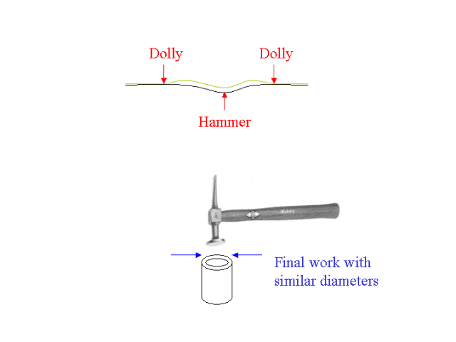
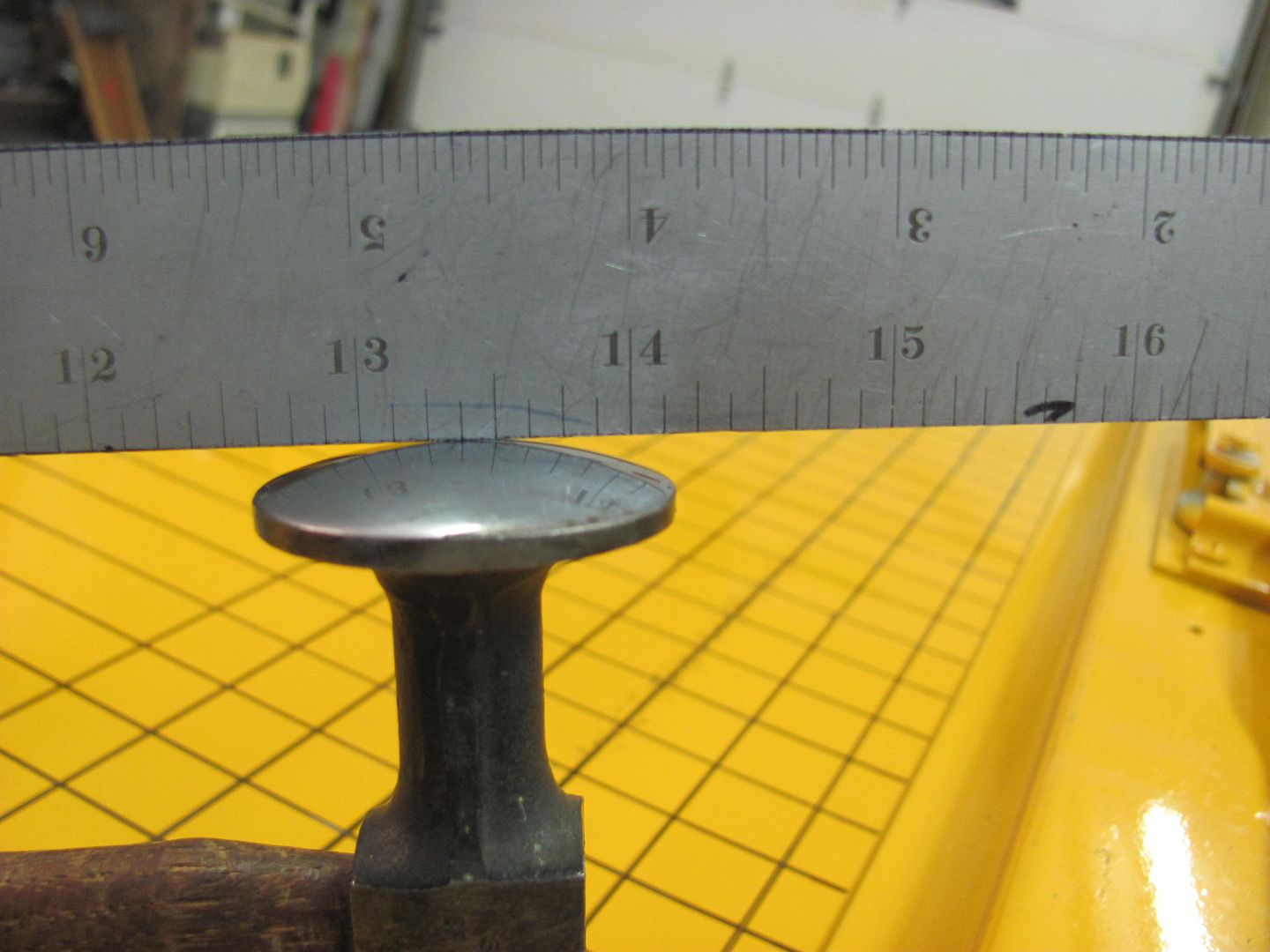
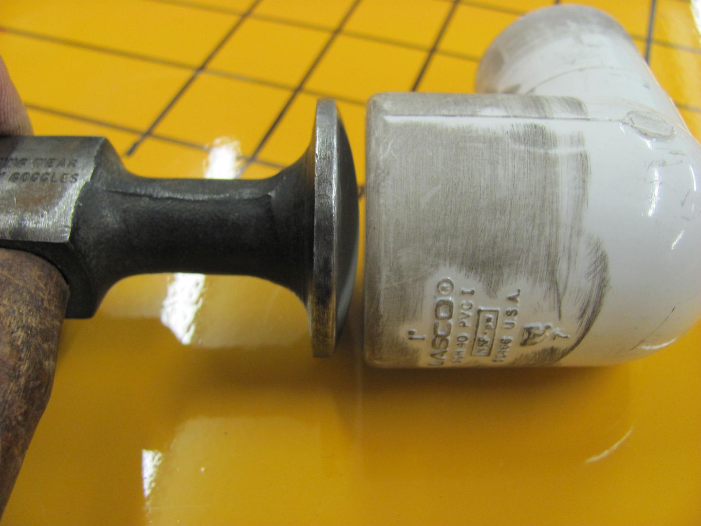
Once our process starts to move the dent, you'll get to a point the outer perimeter has reduced in size. If we don't stop here and regroup, you may end up with the scenario in the upper view, where the dent is now trying to "cave in" on our hollow dolly. This is where a variety of sizes would come in handy, to reduce dolly size as the dent removal progresses to better match the outer perimeter of the dent. When you get to the point where it is only minor movement needed, you'll want a hollow dolly sized the same diameter or only slightly larger than the head of the body hammer. Where a "flat" body hammer in most cases actually has a low crown, this works about perfect to counter the springback effect.


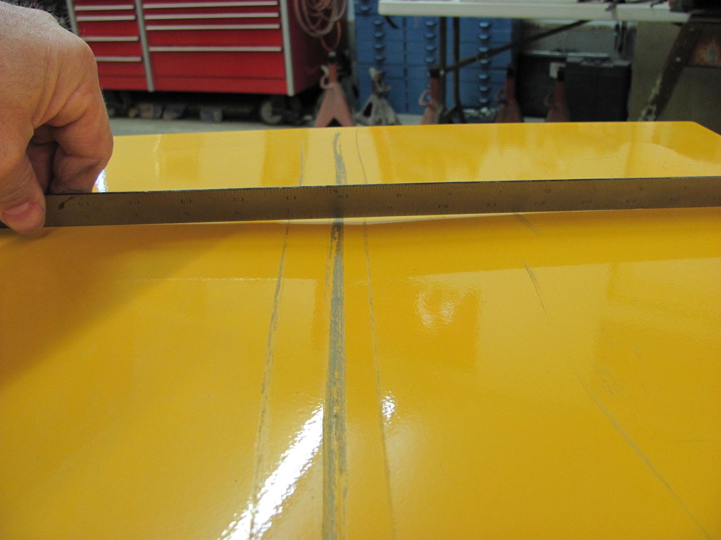
Looking at this another way, the dent has formed an arc (stretch) in an otherwise flat panel. We're trying to return the arc to a flat (flatter?) line. Having a dolly made of a non-metallic material also helps to grab or capture the surface of the panel moreso than a metal dolly would.
 
To avoid these ads, REGISTER NOW!

jarhead

Well-known member
Joined
Jul 9, 2006
Messages
704
Location
Colorado, near Morrison
What would be the best approach to shaving these? In my mind I assume I have to remove the indentation where the hand grip was somehow (a plasma cutter, or a air-saw?)

Then i have to make a radius-ed patch to replace it due to that portion of the door having somewhat of a radius. Then slowly tack that piece in as you have in other examples.

As for the holes where the screw were holding the handle in do I temporally put something behind them to keep the wire from the mig passing through as I weld, or do I build the weld around the edge of the hole and spot at a time until it is full?

Thanks, Joe
 

Attachments

  • shave.jpg
    shave.jpg
    141.8 KB · Views: 143

jarhead

Well-known member
Joined
Jul 9, 2006
Messages
704
Location
Colorado, near Morrison
Joe.
Just cut it all out in one piece and put one piece back in.
Lotta extra work doing 3 different patches.

Thanks, I must of had a complete "brain fart" as that had not occurred to me...

I am awfully close to the body line so i am going to have to be careful, this is my first attempt at something like this. Luckily I have a spare dented door I had to replace so I will do a test door first. This is a 4 door car.

Thanks again, Joe
 

gelierb

Well-known member
Joined
Nov 16, 2010
Messages
52
Location
Redwood City, CA
Got a 3M paint mask and picked up some PPG DP50LV epoxy primer and hardener that I'm going to experiment with in some hidden areas where cosmetics are not so important. Thought I would use a brush to begin with, test out some curing/welding issues and work my way toward spraying a little at some point down the road.

This stuff is "2.1" but on the material sheet I noticed they also seem to call out one part reducer (2, 1, 1 D87xx)? The paint guy didn't mention reducer? Does this mean that in all cases a reducer should be used (temperature notwithstanding)? I want to spray from a smaller gun in future so I'm sure the 2.1 would need additional thinning? I also want the brush work to "wick" into some lapped (original factory designed) seams here and there if possible, so I would think thinner would be better for that - even with the brush?

Also looked at one of those plastic tops that seal to the top of the can with a pour spout and mixer build in - will those keep the primer fresh enough over a period of time (instead of just resealing the can)?

Thanks for any feedback!
 
Last edited:

MP&C

Well-known member
Joined
Oct 21, 2009
Messages
4,396
Location
Leonardtown, MD
Well I guess it's about time for a sequel. I had a left over door from a bus repair earlier this year, and as it was damaged the least, we thought to keep it as a starting point. New ones in primer go for just under 1K, so I think we can save some money here....

The last time I used the "donut dolly" was with the low crown body hammer (the flat one) but when I tried it on this flat panel, progress seemed to be rather slow. I think the low crown hammer was better matched to a crowned panel, and with this panel being flat, I may have better luck with a crowned face body hammer. So as we're starting with bent metal anyhow, what's a little trial and error going to hurt? I'll just keep my fingers crossed that the hammering force would not be great enough to pound dents in the other direction. (we're looking for consistency and moderation ;) )


Picture095.jpg


Here's our dented sample today, an aluminum door skin with a nice crease that travels just about the full length of the door.


Picture084-1.jpg


Picture085-1.jpg


Picture088-1.jpg


Picture096.jpg


As the donut dolly is very closely matched in size to the hammer diameter, accuracy in locating the devices opposite each other is crucial. Depending on the panel you are repairing, this may be a challenge in itself. To keep the tools properly aligned and thus provide a more efficient shrink, I suggest a grid on either side, matched to identical starting points.


Picture089-1.jpg


Picture090-1.jpg


I numbered every fifth one just to keep better track of where I was. Some days you need all the help you can get. Also shown is the damage before starting, located at grid 5, 10, and 15, just for reference of our progress.


Picture091.jpg


Picture092.jpg


Picture093.jpg


As I am working with a flat panel, I am able to use a straight edge to monitor the progress and see where additional shrinking may be needed. If you are using this process on a crowned panel, I would suggest making a profile template matched to the undamaged side of the car. Also, seldom does the crown on a panel remain consistent from one end of the panel to another, so it is very possible you may need different profile templates to accurately guage different sections along the panel.

After about 30 minutes of work, here are the results, again located at grid 5, 10, and 15.


Picture098.jpg


Picture099.jpg


Picture100.jpg


And the light reflection shows considerable improvement over the first pictures....


Picture102.jpg


Picture103.jpg


This is now at a point we could strip the paint off the door, and any remaining defects would be taken care of with high build primer.
 
Last edited:

svwilbur

New member
Joined
Oct 25, 2011
Messages
1
I am going to be attempting to do some patch panels on my 57 Chevy 3100 pickup. The first two will be a small spot on the lower left door about 1 inch by 2 inches or so currently but will have to cut it back to good metal. It may get much bigger.

The second one is the lower 9 inches or so of the left front fender at drivers door area.
It will be a horizontal patch from the wheel well to the door edge.
http://www.classicparts.com/1955-57-Front-Fender-Rear-Lower-Tip-L/productinfo/44%2D815/ and this one http://www.classicparts.com/1955-59-Outside-Door-Bottom-Left/productinfo/44%2D713/

I have not ordered them yet but they look to be about what I would need.

I also need a welder. I have other things I will use it for as well so I thought I might get more than I need for this job as there will be other uses and heavier needs later like welling in a rear cross sill on the truck.

I took a welding class for a semester at a community college and did some Stick and Mig welding on a older Millermatic 180.

So I was looking at the Millermatic 211 MIG Welder Auto-Set with MVP 907422 and a deluxe cart and spoolmate 100 type of setup. It goes 115 or 230 volt. As the 115 it seems to be the same as the MILLERMATIC 140 MIG Welder Auto-Set 907335.
http://www.millerwelds.com/products/mig/product.php?model=M00245

Millermatic 211
handles 24ga to 3/8 mild steel, 18ga to 3/8 (9.5mm) aluminum
Input Power
120 V, 20 A, 60 Hz, 1-Phase
230 V, 25 A, 60 Hz, 1-Phase
Rated Output
90 Amps at 20 VDC, 20% duty cylce (120 V)
150 Amps at 23.5 VDC, 30% duty cycle (230 V)
Welding Amperage Range 30 - 210 Amps
WireDiameter Capacity
.023 - .035 in (0.6 - 0.9 mm) Solid Steel
.023 - .035 in (0.6 - 0.9 mm) Stainless
.030 - .045 in (0.8 - 1.1 mm) Flux Cored


The millermatic 140:
handles 24ga to 3/16 mild steel, 18ga to 14ga (1.9mm) aluminum
Input Power
Requires 1-Phase power 115 V, 20 Amps, 60 Hz
Rated Output
90 Amps at 18 VDC, 20% duty cycle
Welding Amperage Range 30 - 140 Amps
WireDiameter Capacity
.024 - .030 in (0.6 - 0.8 mm) Solid Steel
.024 - .030 in (0.6 - 0.8 mm) Stainless
.030 - .035 in (0.8 - 1.2 mm) Flux Cored

One with the cart and spoolmate is about 1400 and the other is 1000 (on ebay)

So on to my question. I know they are both probably overkill for welding the 18 gauge sheet metal on this truck but will they work OK if I just do the spot welds and let it cool and grind and planish like you have been talking about with maybe a bit of hammer and dolly work as needed?

Any reason to prefer one welder over the other between these two (MillerMatic autoset 140 and 211)?

These have "smooth-start technology" suppose to eliminate some of the spatter at start-up which is about all you do in the case or spot welding these panels on. Is that going to help or screw up the weld?

Anyone try using one of these in autostart mode?

Here is some pictures of the areas that need some work done on them. Well there are lots but these are the first few areas I wanted to start on.
http://home.comcast.net/~svwilbur/ChevyPU57_bodywork.html

-Stacey (yes, I got a girl's name. But I am a 56 year old male)
 

MP&C

Well-known member
Joined
Oct 21, 2009
Messages
4,396
Location
Leonardtown, MD
From post #229:

For much of the "hidden" patches, you can many times get by with leaving them as is because no one will normally see them, but I like to use these as "practice samples" for when it does count. You can watch the metal, see how it reacts to heat from welding, see how the planishing efforts will correct the distortion. Then you will be better prepared for the patches you can see, like the bottoms of the fender. See post 3 on page one, it will show a bit of planishing the weld "dots". As explained in the post above (response to Monkeynutz re: Opel GT), if you can find/fabricate a patch that goes straight across the entire bottom of the fender and not just a corner, you will have the shrinking forces only pulling toward the one weld, for what may prove to be an easier job of planishing out the distortion. A corner patch will have two perpendicular welds, where the shrinking forces on the inside corner tends to add together and will make planishing that area more of a chore. That's why if you are forced to use inside corners on your patches, most people will put a wide sweeping radius instead of a sharp 90, to minimize those "doubling" effects. This is shown on post 93, on the Biscayne fender patch. I'd say if I had to do that one over again, it would have been a better job if we had just gone straight across the entire bottom with the patch we made.

This may help to reduce some of the effects from shrinking during the weld process. In addition, looking at the lower door skin, you may want to replace the complete bottom of the skin and not just the corners. For both the reasons listed above, and also it looks like you may have other pin hole damage lurking and ready to come through....
 

MP&C

Well-known member
Joined
Oct 21, 2009
Messages
4,396
Location
Leonardtown, MD
Just an update, in answering some questions on this subject on another forum, I realized some of the pictures I showed earlier in this thread may have been a bit confusing as they only show the shrinking in one direction, when actually it will occur in multiple directions. So to clarify, here are some examples of shrinking readily found when welding in patches:

First, looking at welding a lower door skin on, you'll have shrinkage throughout the area of the weld (red line in picture) and the HAZ (heat affected zone) on either side of the weld. As the resulting shrinking occurs, the door skin will lose some of the crown and flatten out (green arrows) as well as the length shortens (blue arrows). As a result of the weld and HAZ shrinking horizontally (blue arrows), and the adjacent area above and below having a tendancy to resist this movement, the area in between will start to buckle, or cause a wave effect (yellow lines). To visualize this effect, lay a piece of paper flat on a table and using your index fingers, push two corners of the paper toward each other. This simulates the shrinking caused by the weld. You'll notice the paper creates a wave or buckle as you push the corners together. This simulates the buckles in the area surrounding the HAZ. When reading your panel, don't be fooled as these buckles may be misread as a stretch, or high, but it's actually unaffected panel being manipulated by the adjacent shrinking.

Door1.jpg


Next, if you are just welding a patch into the corner of a door skin, you'll have a compounding effect in the shrinking as the forces combine in the inside corner. The shrinking effects will normally occur in an equal amount on both sides of the weld and HAZ, but looking at the inside corner you should be able to see how these forces will "stack up". In addition, the linear shinking (blue arrows) will tend to have more of a "stacking" effect on the inner corner where you'll see a more pronounced buckle (normally outward) there as compared to the waves on outside of the corner (yellow lines)

Door2.jpg


To address these repairs, planish the weld/HAZ to stretch both in a linear fashion (removing waves/buckles) and also restoring the crown. This repair will also very likely include some metal bumping (off dolly) to raise/lower highs and lows as the metal begins to relax. Hope this helps in reading the panel and some of the secondary effects (waves/buckles) of the shrinking that you'll see. Planishing the welds as you go will help to keep these effects in check, where it will be less likely you'll see all the waves and buckling. It's when you have all these forces/reactions combined (from not planishing) that some may have a harder time reading the panel...
 

nonhog

Well-known member
Joined
Nov 6, 2007
Messages
2,449
Location
Arizona (Tucson)
Robert, ever thought about doing a video? I have David Gardiners DVD and I love it but always nice to get other approaches.
 

MP&C

Well-known member
Joined
Oct 21, 2009
Messages
4,396
Location
Leonardtown, MD
Although I haven't given it much thought, I have had similar arm twisting before.. I know I'm not up to David's level of expertise by a long shot, let me work on it some more :beer:
 
Last edited:

sic

New member
Joined
Nov 12, 2011
Messages
4
some amazing work MP&C!

didn't really read through this entire thread, as that's a lot of reading. but i'll be coming back to it later to catch up on it.

figured i'd add a little to this thread myself...here's some in progress pic of a 1984 c10 that i've yet to finish, rather than patch rust, i remove unnecessary holes :)

http://sphotos.**.fbcdn.net/hphotos-snc6/181913_1783083224302_1456126901_1892759_3934457_n.jpg

http://sphotos.**.fbcdn.net/hphotos-ash2/181737_1783083424307_1456126901_1892760_4703057_n.jpg

168330_1783083584311_1456126901_1892761_7580492_n.jpg


168324_1783083784316_1456126901_1892762_3504434_n.jpg


http://sphotos.**.fbcdn.net/hphotos-prn1/30588_1453412302735_1456126901_1153314_4925819_n.jpg
 

outtaplace

Active member
Joined
Jan 21, 2011
Messages
37
Location
Central NJ
Here are some patch panels I'm putting into my 65 Dodge. It's my first project doing body work so it's going slow, but I am making progress...

Driver-side quarter - probably the worst place it could have rusted. There are two layers here. I did it in 5 separate pieces cause I **** at bending/forming:
IMG_6931.jpg


IMG_8413.jpg


Trunk:
IMG_8553.jpg


IMG_8562.jpg


IMG_8565.jpg


IMG_9719.jpg


IMG_9726.jpg


IMG_9731.jpg


IMG_0065.jpg


IMG_0068.jpg


IMG_0072.jpg
 

liljohn320

New member
Joined
Jan 14, 2011
Messages
1
Location
langhorne pa
Hello to all.
New guy here. Just wanted to say hello and say how much I enjoyed
this thread on Patch Panels. I've learned a lot. I'm trying to get my 49 F1
back on the road after sitting for 20 years. Lots of holes so this thread is
the right stuff at the right time. Thanks again for all the valuable info.
John
 

MP&C

Well-known member
Joined
Oct 21, 2009
Messages
4,396
Location
Leonardtown, MD
Nice job on the trunk floor!

John, lets see a build thread started on that truck!


As a follow up to Post 247, I have some more Bus parts coming in for repair, so I'll use the opportunity to paint the repaired door as well. I scuffed the door and applied some Evercoat 416 glazing for the remaining minor defects. The minimal amount shown here indicates how well the aluminum skin responded to the donut dolly shrinking.


Picture177.jpg


Picture178.jpg


Picture179.jpg
 
Last edited:

sr_stetler

New member
Joined
Apr 24, 2012
Messages
1
photo.php
[/IMG]
mp&c great work....i was wondering if you can give me any pointers to make my repairs alot more like yours
 

54FordPanel

Well-known member
Joined
Aug 7, 2009
Messages
5,711
Location
Fort 54, Littleton, Co
Robert, (and anybody else) I have a couple of questions:

I am welding in patch panels on my '82 Jeep Cherokee. I am drilling out the spot welds on some sections, and will be doing lap joints with rosette welds to on some sections to join them back together again like the factory.

On some of the lap joints that I am taking apart, it seems like there is seam sealer in between the lap joints. I don't think I can do that, because it would goof up the welds, right? Do I just put seam sealer on the outside after the rosette welds are completed?

Is there a way to put seam sealer in between the lap joints, without it melting all over and messing up the welds? Or does the seam sealer just go on the outside and that's it?

IMG_2974.jpg

IMG_2976.jpg


Also, I am trying to save this fender flare I cut out of a parted out Jeep to replace my rusty one. As you can see, it was really folded over.....Is this too far gone to save? I've got it pretty straightened out, but the part that was folded over is now a sharp point, without a nice rounded edge. Would I be better off cutting out that sharp edge crease and welding in a new rounded section?

IMG_2940.jpg

IMG_2946.jpg

IMG_2949.jpg
 

MP&C

Well-known member
Joined
Oct 21, 2009
Messages
4,396
Location
Leonardtown, MD
Seam sealer will contaminate welding. To protect the metal in between I would suggest epoxy primer on the separate surfaces, and clean out the paint in the plug weld hole with the modified drill bit shown earlier in this thread, or use some weld through primer. Then once you have primed after the panels are welded together, use the seam sealer over the joint.

On the flare, maybe I'm missing something, but the last picture looks pretty good. With a dent like you showed, there is some stretching that occured, so you may need to shrink those areas to get it perfect.
 
Last edited:
To avoid these ads, REGISTER NOW!

-->

Well-known member
Joined
Dec 19, 2010
Messages
1,501
Location
NY outer borrough.
years ago is was considered not a good idea because then body fillers didn't stick well to the braze, and over time would bubble.

Not sure now though, fillers are a lot better now than then.

My father did this years ago using old coat hangers and an acetylene torch. Came out great and is still holding up in the areas repaired. He was a pro welder though and knew what he was doing.
 

kent_323is

Well-known member
Joined
Nov 13, 2009
Messages
274
Location
South Dakota
Robert,
I've enjoyed reading through this entire thread, and wanted to express my appreciation for the time and effort you've taken to relay this information. You've done a great job with pictures, diagrams and explanations, and I've certainly learned a lot. I look forward to seeing more posts from you on this subject.
Thanks again,
Kent
 

b-body-bob

Well-known member
Joined
Oct 10, 2011
Messages
1,621
Location
Almost Heaven
Agreed, this is a great thread and thanks to all who have participated. My patch panel nightmare, I mean project, is about to get started now that I cut the old patch off. I've got a new quarter skin on the way, the plan is to replace from just above the body line below the side marker, front to back. Threads like this one here and at the HAMB are what have given me the cojones to even attempt this ...
 

Attachments

  • DSCN0817.jpg
    DSCN0817.jpg
    49 KB · Views: 237
  • DSCN0834.jpg
    DSCN0834.jpg
    48.3 KB · Views: 222

41ratrod

Well-known member
Joined
Aug 3, 2010
Messages
496
Location
Springfield Mo.
Thanks guys for posting all the info. I wish I'd had this read this in '06 when I shopped the top on a Chevy Astro panel van . I knew to tack weld it and not to make any welds more the 2" long. Great thread.
 

MP&C

Well-known member
Joined
Oct 21, 2009
Messages
4,396
Location
Leonardtown, MD
Robert,
I've enjoyed reading through this entire thread, and wanted to express my appreciation for the time and effort you've taken to relay this information. You've done a great job with pictures, diagrams and explanations, and I've certainly learned a lot. I look forward to seeing more posts from you on this subject.
Thanks again,
Kent


Kent, glad to help out. In Feb of 2011, I did a metalshaping demo at OJ Higgin's speed shop (post 215 and 220), which brought guys in from MD, VA, PA etc. During the demo, one of the guys had an epiphany moment as some of the responses I was giving to questions from the audience were verbatim to what he had read here in this thread. He was a member of another forum, but someone had linked this thread on that forum for a how-to on rust repairs/welding in patch panels. He figured out after about an hour into the demo that the guy doing the demo (me) was the same one that had written quite a bit of what he had read online. This thread has morphed into a good reference, and it was nice to find that other forums were using the info in this thread to their benefit as well.


B-body-Bob, I have heard that some of the replacement panels for some of the mopars were not all that accurate around that rear side marker light, so your plans for the cut line should eliminate that trouble spot..
 
Last edited:

b-body-bob

Well-known member
Joined
Oct 10, 2011
Messages
1,621
Location
Almost Heaven
B-body-Bob, I have heard that some of the replacement panels for some of the mopars were not all that accurate around that rear side marker light, so your plans for the cut line should eliminate that trouble spot..

Yes, that's a fact. This link shows new laying over original.
http://www.moparmusclemagazine.com/techarticles/body/mopp_0507_panel_rust_removal_2/photo_09.html
I don't know how you'd even mount the marker with the hole cut like that. The article from that link is how I'm going to do the fitting, and welding.

A smart man would just replace the whole quarter but I'm not one of those.
 

lilredex

Well-known member
Joined
Apr 29, 2006
Messages
5,945
Location
Toronto
This marker hole was repaired in 1986 when my choices were O/A or a Lincoln buzzbox. I cheated a bit and put very small offsets on those patches. Hardly noticeable from the rear side of that quarter.


35nahib.jpg


jkacys.jpg


2dwhnqg.jpg


2lntst5.jpg
 

PCO6

Well-known member
Joined
Dec 25, 2008
Messages
4,573
Location
Newmarket, Ontario
This marker hole was repaired in 1986 when my choices were O/A or a Lincoln buzzbox. I cheated a bit and put very small offsets on those patches. Hardly noticeable from the rear side of that quarter.
lilredex - That looks like a typical Toronto car. If you repaired it in 1986 it must have been what ... 3 years old at the time? :lol: Good job btw.
 

lilredex

Well-known member
Joined
Apr 29, 2006
Messages
5,945
Location
Toronto
Thanks, it was actually a 1977. We bought it in 1980. Like a lot of Volares, it did go downhill quickly.
 
Last edited:

outtaplace

Active member
Joined
Jan 21, 2011
Messages
37
Location
Central NJ
Some more progress from post #254. Driver side lower quarter....

IMG_0949.jpg


I had previously added the strip along the left side of the wheel well and the straight piece that goes long the lower part of the trunk floor with the flat bottom on the body plug circle cutout:
IMG_0951.jpg


Here I did my best at pretending to be MP&C while fabbing the patch panel :D...I don't have a bean bag or anything fancy so I just used some old bathroom towels that got demoted to shop rags. They worked pretty well as a soft back for hammering the curve into the panel:
IMG_0954.jpg


IMG_0953.jpg


The rough fitting and first strip of welds:
IMG_0955.jpg


Some more welds:
IMG_0956.jpg


Nearly finished - just a few pin holes to fill:
IMG_0959.jpg


The contour isn't perfect so I may try some shrinking or I may just leave it. It looks decent from every angle except if you're laying on the floor:
IMG_0965.jpg


IMG_0964.jpg
 

92GreenYJ

Well-known member
Joined
Jun 9, 2012
Messages
488
Location
San Diego, CA
Sheet is a pain to weld. But with low heat and high line speed it's doable. I couldn't find those fancy clamps when I went to HF for my YJ rocker panel repair. So I wound up using a bunch of c clamps to hold it in place. Tacked several inches apart and slowly went back and filled in the gaps skipping around to prevent war page and occasionally massaging the panel where it needed to be with a hammer and dolly. Not too bad for my first real sheet metal surgery job in my opinion.

DSCN0343.jpg


DSCN0345.jpg


DSCN0346.jpg


DSCN0349.jpg
 

robmack

Well-known member
Joined
Jul 16, 2010
Messages
46
Location
Toronto, CANADA
Thanks for the useful instructions and insight in this thread around patching sheet metal panels.

I have a unique challenge and thought some of the experts here might advise. I've purchased a pair of BMW Slash 5 headlight mounting ears for a motorcycle customization project. This is a picture of how they look installed on a '71 BMW R90S (p.s. not my bike):
Untitled.jpg

Notice they taper from top to bottom, being 2-1/4" diameter at the bottom. Normally these ears sit between the triple trees with rubber bushings to dampen vibrations that prevent damage and maintain spacing from the fork stanchion.

Since I am fitting these ears to a non-standard fork, I need to extend the length of the tubes by 22mm (~3/4"). I am thinking that fabricating a sheet metal tube and welding it to the bottom of the ear will accomplish my goal.

So, my question is will the techniques for tack welding with a MIG welder work with small metal parts such as this? Also, will I encounter any unforseen problems since the metal extension will be tubular and not flat as in a body panel patch?
 

bgarrett

Well-known member
Joined
Feb 11, 2006
Messages
4,393

Its not necessary to buy these clamps when it is so easy and satisfying to make your own. You can make 20 of these in about 30 minutes. I use 3/4 EMT and a 5/16 bolt. First cut off the head of the bolt, hacksaw a slot in the bolt to braze a piece of banding material, add a washer and a nut. You can use a wingnut. I always finger tighten. The banding material leaves just the right gap to weld. Put a hole in the banding and use a headless nail. Banding material is easy to find and is always free. I recently got some from the lumber yard. They were using it around treated poles and railroad ties.
The pictures show one disassembled, one assembled, then in use front and back sides
 

Attachments

  • shmtl clamps 002.jpg
    shmtl clamps 002.jpg
    17.6 KB · Views: 329
  • shmtl clamps 004back.jpg
    shmtl clamps 004back.jpg
    33.9 KB · Views: 285
  • -shmtl clamps 003inplace.jpg
    -shmtl clamps 003inplace.jpg
    25.7 KB · Views: 275

MP&C

Well-known member
Joined
Oct 21, 2009
Messages
4,396
Location
Leonardtown, MD
.....Since I am fitting these ears to a non-standard fork, I need to extend the length of the tubes by 22mm (~3/4"). I am thinking that fabricating a sheet metal tube and welding it to the bottom of the ear will accomplish my goal.


If you need longer tubes, IMO cut off the headlight brackets and weld them onto new tubes cut to the correct length. It will be easier in the long run, and will give a cleaner look.
 

Racecarl

Well-known member
Joined
Oct 25, 2008
Messages
474
Location
McCook, NE
This thread is exactly what I have been needing. I read the whole thing three times now and went out to the shop tonight and tried my new-found knowledge. The results were a radical improvement over what I had been doing and I was able to get a small area fixed that I have been fighting for a while.
 

gelierb

Well-known member
Joined
Nov 16, 2010
Messages
52
Location
Redwood City, CA
I started using House of Kolor epoxy primer about 15 years ago, painting some Harley tanks. Got them primed and guide coated, and forgot the owner wanted the tanks sealed (creamed). First part of the sealing process is the cleaning process, where you place a section of sash chain inside the tank, along with their cleaning solution, MEK. The chain is to knock any loose material (weld slag, etc) off, and works via agitation. (yes, shake it up) Yours truly thought I could do this without a cap in place, and soon I had MEK running down the side of the tank, guide coat running off with it. Stopped what I was doing, wiped down the tank, and the only thing the MEK touched was the guide coat. EP never budged, didn't wipe off, nothing on the rag.

All that said, it is not without it's issues. I've been using it ever since on restorations and motorcycle work, and the only problem I've ever encountered with the H/K EP was after spraying over an owner's application of Ospho on his Model A street rod. And just like most compatibility issues, the problem doesn't show up until a few months later after it's been sitting in the sun. A call to H/K tech line confirmed, their EP did not play well with rust conversion type products. I was told to abrade the metal to get rid of any rust, fix anything that wouldn't turn shiny (replace rust with new metal), and paint directly over the bare metal. I haven't had any issue since with the H/K EP. I don't really use the rust conversion products; I don't care for POR products except in some inaccessibility circumstances; but I am a firm believer in replacing what looks like crappy rusty metal with new shiny stuff. That new shiny stuff tends to hold paint for a good while longer than something with "converted" rust ....any day of the week.

Now I'm not telling you to rush out and buy H/K, this wasn't to plug their product. But it should show that you need to look at your complete paint job and insure compatibility throughout to eliminate problems like the one I described above. Some brands of EP will have reaction issues when sprayed over etch primer, in much the same way as my issue with Ospho, so some reasearch is in order before rushing out to buy a rust conversion product or getting some etch primer because that's what your neighbor from the body shop uses. Another consideration would be close proximity of a paint jobber to your area. If it's easier to drive somewhere and pick up another quart if you think you'll run low, it may make one brand more appealing if that's what they carry. I think all are comparable, and all likely have their little quirps. I would be curious to ask why you say PPG DP is no good. Not that I'm using it or defending it, but trying to learn something. I've heard some people say they can wipe it with laquer thinner and the paint comes off on the rag, and yet others say that once fully cured, nothing touches it. ????

Which kinda brings this to another point, why was someone using laquer thinner on the epoxy? If it was to test the paint, that's one thing. If it was to use as a preclean, that would be another issue:

A wax and grease remover is typically a slow evaporating solvent, which allows it to "float" the impurities to the surface where a final wipe will remove them. If you've ever used W&G remover, you'd have seen how it leaves a film upon first application. Most manuf. recommend using one cloth to apply, and a second to wipe. Some people choose to use Laquer thinner without fully understanding this principle. Lacquer thinner dries too fast to perform as effectively as W&G remover. Once you have wasted time, money, and material from having fisheye show up in your paint, any extra expense for purchasing the right product for the job will be well worth it.

On the primers, my personal thoughts are the Epoxy will give you a better, more stable base. For the enthusiast or restoration shop, it may make more sense than it would to a production shop, who expects to have your car out the door in three days. In that time frame most EP's would not fully cure. But for the quick turnaround the production shops are looking for, perhaps the etch primer gives a better bite where something didn't get prepped as meticulously as it could have, and the 2K gets things done more quickly than the EP. Safe to say these are products that are really designed for the collision industry, and not restorations. So use caution if you look to your local paint supplier for their recommendation, they will likely steer you toward buying what they sell the most of, and their largest customer base is the collision industry.

Other brands that have epoxies include Dupont, PPG, SPI, Sherman Williams, and many others. (Yes, Sherman Williams does make industrial coatings) Most of these will also have a value line product, (i.e: H/K is Valspar, Dupont is Nason, etc.) Like I said earlier, most are comparable products, slight differences here or there. Some are direct to metal primers, some need an etch first, others may not be compatible with etch primers. So there, I've probably given you more questions than answers, but it should help you a bit more in what to look for in your research.
Funny but I still find myself returning to this thread like some kind of reference manual. Thanks again Robert.
 
To avoid these ads, REGISTER NOW!
Top Bottom