To avoid these ads, REGISTER NOW!

Welding in patch panels

MP&C

Well-known member
Joined
Oct 21, 2009
Messages
4,396
Location
Leonardtown, MD
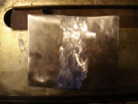
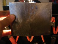
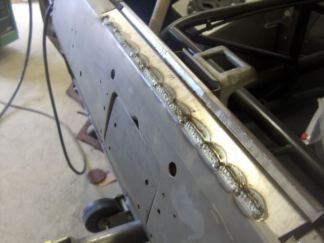
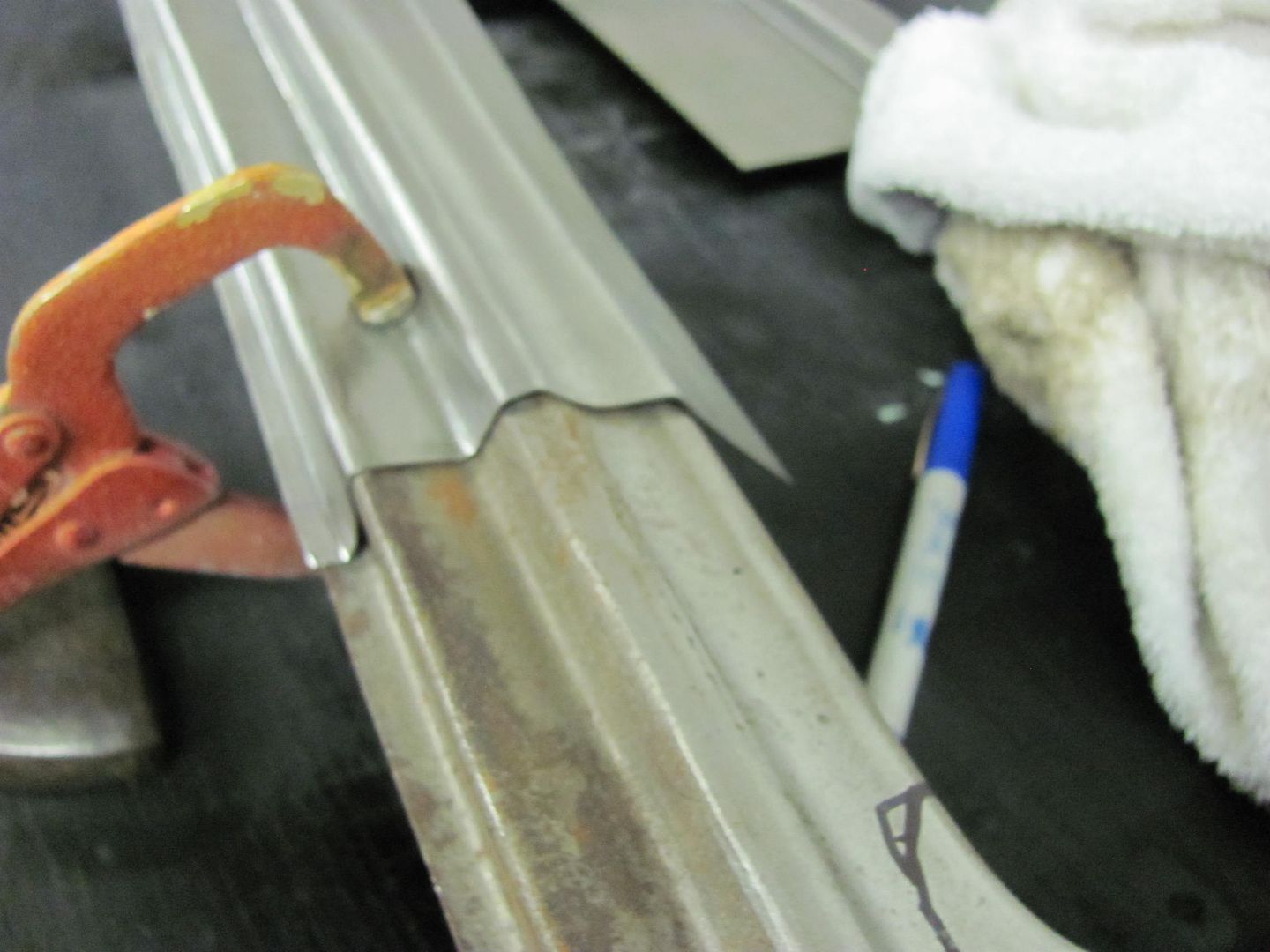
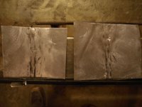
I'm going to use this picture as our starting point. The weld penetration is insuficient, by the time you grind down the weld on the opposite side, you lose the majority of the structural integrity of the joint. Whatever setting this used, I would go to the next higher heat, and the recommended wire feed for that heat. If it blows holes, turn the wire feed up just a bit.


attachment.php


I personally don't bevel the panel edge, but Randy Ferguson (Ferguson Coachbuilding) recommends it. See here:

http://fergusoncoachbuilding.blogspot.com/

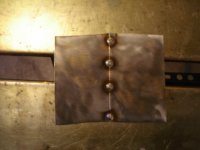
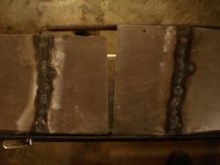
It will remove some of the mass where you shouldn't need as much heat to perform the weld. I would still **** the panels tight together, any gap is going to increase your chances of blowing holes. Be sure to have the surfaces flush across also, the bevel may make this more challenging. Something else I'll recommend, as I've changed some of my methods as well, once your weld dots are about an inch apart, stop placing the next welds in the center of the unwelded panel (between two dots). At this point, revert to overlapping the last sets, planish, grind, repeat. But changing to an overlap instead of finding the next center of the unwelded, you will eliminate the pin holes and missed welds, where you won't need to mark the panel.
 
Last edited:
To avoid these ads, REGISTER NOW!

Doug_B_928

Member
Joined
Nov 6, 2012
Messages
12
Location
Winnipeg, Canada
Thanks for the feedback and advice, Robert. I will do exactly as you've suggested and report back. One question in the meantime: When you "planish," what determines how hard you hit the tack? Are you trying to flatten it a bit?
 

MP&C

Well-known member
Joined
Oct 21, 2009
Messages
4,396
Location
Leonardtown, MD
You are just looking to overcome the slight bit of shrink, so if the panel matches the contour of the adjacent metal, then you should be good. For a panel with a bit of crown, the shrinking effect will tend to form a slight depression; as the "arc" of the crown shrinks it tends to form a straight line, hence the depression or "valley" that you may see forming. Your planishing efforts should restore the original shape.
 

buening

Well-known member
Joined
Dec 17, 2007
Messages
1,338
Location
Decatur, IL
Excellent thread and thanks for all the info Robert!

So do you have a monkey in the trunk holding the dolly when planishing welds on a quarter panel replacement? :lol: 
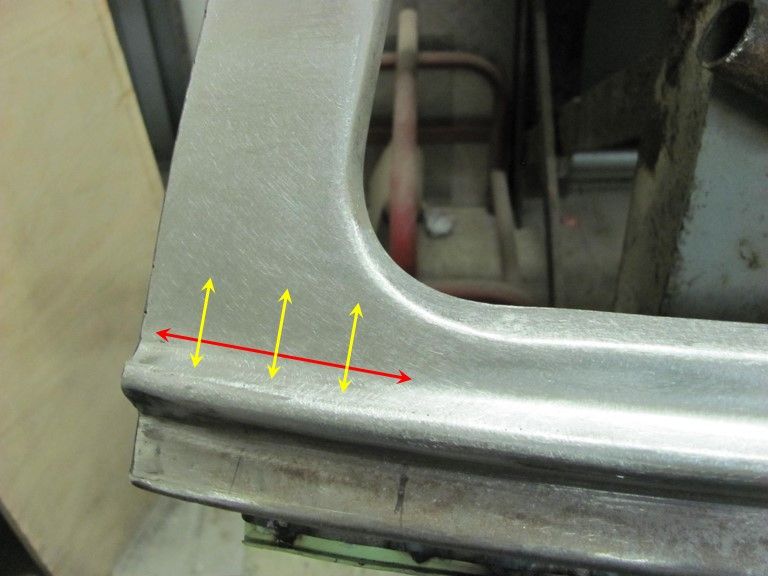
Any tricks on planishing large panels where reach is a problem?

The previous owner of my Mach did a flanged quarter replacement, and yep you guessed it a ghost line is present at the flange. As soon as my welding skills get up to par, I'll be tackling that mess. No matter how good the finishing skills are on the outside with a flange repair, its always visible from the inside (in my case with the trunk open).
 

MP&C

Well-known member
Joined
Oct 21, 2009
Messages
4,396
Location
Leonardtown, MD
When we did this seam, I had my nephew inside with the dolly and me outside on the hammer..


Picture050-1.jpg


If you have welded your tacks in sporadically (spaced), you can pick out pretty well the location on either side, or use a numbering system, whatever works. If you've ever hear the ping noise from an on-dolly planish, then you can use that as well. If someone inside is holding the dolly against the weld seam, some very light taps on the outside will find the dolly via the ping noise, and then you can give it a good rap with the hammer. Basically, whatever works for you.

And the next time you get a chance, could I get you to take a pic of that ghost line as well as the flanged repair inside? I know I've told many people of that side effect, but it would be nice to have pictures to show. Thanks...
 

IONH

Well-known member
Joined
Feb 12, 2010
Messages
2,043
Location
Central Massachusetts
The previous owner of my Mach did a flanged quarter replacement, and yep you guessed it a ghost line is present at the flange. As soon as my welding skills get up to par, I'll be tackling that mess. No matter how good the finishing skills are on the outside with a flange repair, its always visible from the inside (in my case with the trunk open).

Can you post a couple pictures of the inside and outside so we can see the work?
 

MP&C

Well-known member
Joined
Oct 21, 2009
Messages
4,396
Location
Leonardtown, MD
Doug, took some closeups for you tonight.

All clamped up....tightly


Picture150-1.jpg


First set of tacks...


Picture151-1.jpg


Picture152-1.jpg


Weld penetration, the back side....


Picture153-1.jpg


Picture154-1.jpg


Here's an example of the weld, planish, grind, overlap, repeat...


Picture156-1.jpg


Picture160-1.jpg


Planishing as you go helps to keep the panel's shape in check...


Picture162-1.jpg


Still needs a bit of bumping but not too bad overall..


Picture163-1.jpg


Picture164-1.jpg
 
Last edited:

Doug_B_928

Member
Joined
Nov 6, 2012
Messages
12
Location
Winnipeg, Canada
Wow, thanks for the additional pics Robert! Below are pics of today's attempt. I tried very hard to get the kind of penetration you do, but, as you will see, it was difficult for me. What I'd notice is I'd get a good orange puddle of a tack, then when I'd stop the puddle would "**** down" and sometimes burn through and other times just be not quite deep enough. So, I'd increase the wire speed to get more material but couldn't get it the way you have yours. I did, however, get better penetration than before. The settings on my welder for 20 gauge are something like 2.5 wire speed and E.5 voltage. The pic below shows where I ended up. The tacks would penetrate on this setting, usually, but the top side of the tack tended to look porous; like lava. You can see in the pics I had a number of holes from burn through and/or the tack being too shallow from "sucking in." In the finished result, I always seem to have valleys on either side of the weld. I was very careful with my grinding and sanding, so I don't think that is the cause. It's almost as though the heat of the welding is making a little depression in those areas. Here are the pics, quite the contrast from yours:
 

Attachments

  • Welding attempt February 19 029.JPG
    Welding attempt February 19 029.JPG
    140 KB · Views: 183
  • Welding attempt February 19 033.JPG
    Welding attempt February 19 033.JPG
    141.1 KB · Views: 178
  • Welding attempt February 19 024.JPG
    Welding attempt February 19 024.JPG
    140.3 KB · Views: 205
  • Welding attempt February 19 014.JPG
    Welding attempt February 19 014.JPG
    135.7 KB · Views: 191
  • Welding attempt February 19 004.JPG
    Welding attempt February 19 004.JPG
    124.4 KB · Views: 194
  • Welding attempt February 19 001.jpg
    Welding attempt February 19 001.jpg
    25 KB · Views: 208
  • Welding attempt February 19 039.JPG
    Welding attempt February 19 039.JPG
    114.7 KB · Views: 177

Bad dad

Member
Joined
Oct 25, 2010
Messages
13
Location
London, England
Robert,

Well done as ever, that one series of photos is an clear instructional session on it's own. I still haven't had time to do anything on my old Jeep except get it sand blasted. But when I finally do I'll be going back through this thread from the beginning and practicing on some scrap. Thanks again for your time and info.

Douglas.
 

buening

Well-known member
Joined
Dec 17, 2007
Messages
1,338
Location
Decatur, IL
Doug B, what wire stickout length are you trying to keep when doing these tacks? More stickout will be a colder tack, whereas smaller stickout will be hotter. I'm not sure if Robert has addressed this in his recommendations. If you are getting porous welds, its likely your sheilding gas isn't getting to your weld....either through way too much wire sticking out or not enough shielding gas volume.
 

Doug_B_928

Member
Joined
Nov 6, 2012
Messages
12
Location
Winnipeg, Canada
Buening, you were absolutely correct about not getting enough gas to the weld. I tried to increase the amount, but there was no improvement. However, it turns out that the guy who set up the welder (me :( 
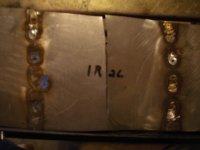
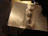
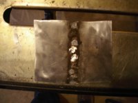
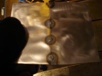
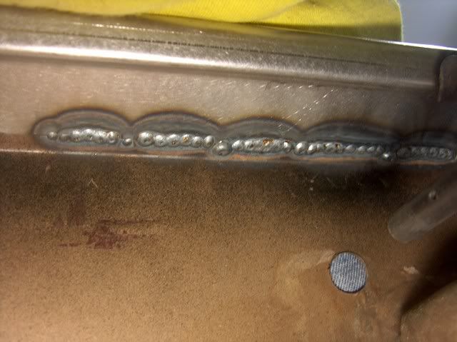
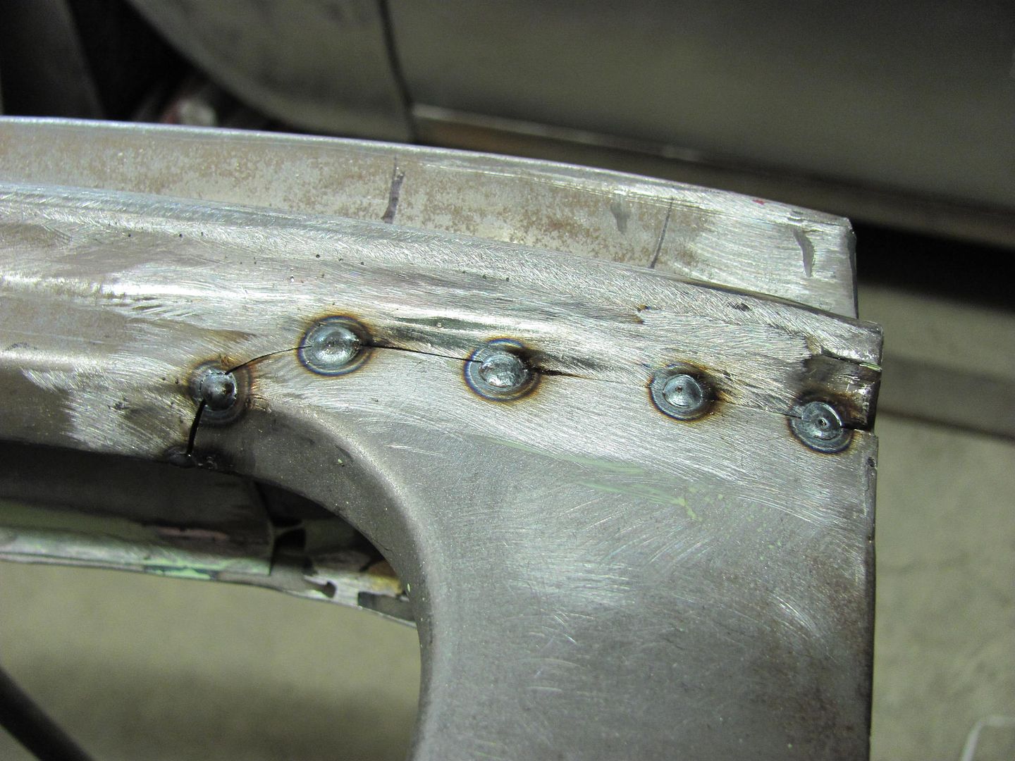
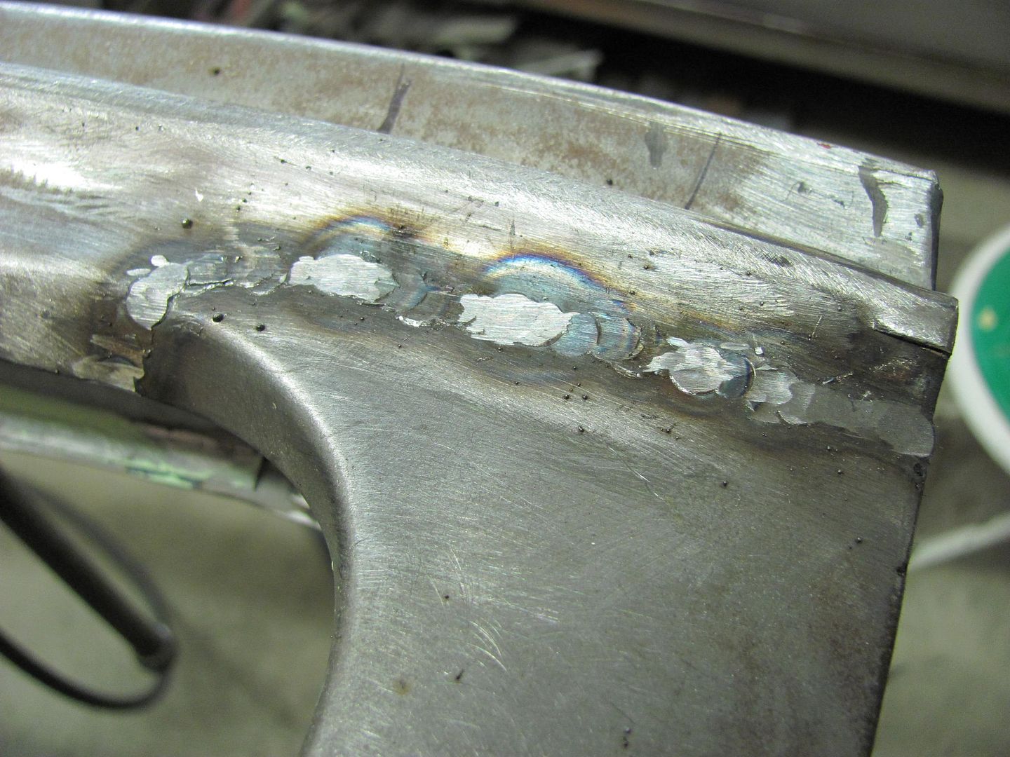
) didn't get the gun line seated properly in the welder. So, the gas was escaping at the front of the welder rather than from the gun tip. Once it was connected properly my tacks suddenly looked like Roberts!!!!!! Below is the result with proper gas flow. I got a little carried away with the grinding, which is why it's not perfectly smooth in appearance.

Thanks, guys, for all of your help!
 

Attachments

  • Welding attempt February 21 009.JPG
    Welding attempt February 21 009.JPG
    136.5 KB · Views: 197
  • Welding attempt February 21 002.JPG
    Welding attempt February 21 002.JPG
    137.2 KB · Views: 224
  • Welding attempt February 21 008.JPG
    Welding attempt February 21 008.JPG
    142.1 KB · Views: 199
  • Welding attempt February 21 014.JPG
    Welding attempt February 21 014.JPG
    131.2 KB · Views: 176
  • Welding attempt February 21 012.JPG
    Welding attempt February 21 012.JPG
    142.9 KB · Views: 192
  • Welding attempt February 21 003.JPG
    Welding attempt February 21 003.JPG
    116 KB · Views: 211
  • Welding attempt February 21 011.JPG
    Welding attempt February 21 011.JPG
    137.9 KB · Views: 200

Doug_B_928

Member
Joined
Nov 6, 2012
Messages
12
Location
Winnipeg, Canada
Robert, are you grinding the backside of the tacks at the same time as you grind the top side? Despite planishing, I'm getting little valleys on either side of the weld bead. I'm thinking that maybe if I grind the back side of the weld too I'll be able to get those valleys out as I go.
 

Doug_B_928

Member
Joined
Nov 6, 2012
Messages
12
Location
Winnipeg, Canada
So, there is one niggling problem with my practice welds. In my earlier attempts I thought I had messed up the grinding, and I did, but the reason was that I was trying to get out these small depressions just to the side of some of the tacks. They are the dark spots shown in the pics of different attempts below. I'm assuming that these would be no problem with filler, but am wondering if anyone can tell me why this is happening and how to prevent it. I'd like my finished product to look more like Roberts, but realize that this might take years of practice. As instructed, I carefully grind and planish both sides but these depressions still appear. Also, on a few of the pieces I tried different heat settings. I can imagine that these depressions are shrinkage from the heat of the tack, but they will not planish out (and they really aren't visible until all of the grinding and sanding is done. However, these depressions appeared even on the recommended settings for this gauge (20) of steel....
 

Attachments

  • Welding practice 010.JPG
    Welding practice 010.JPG
    129 KB · Views: 137
  • Welding practice 014.JPG
    Welding practice 014.JPG
    127.5 KB · Views: 129
  • Welding practice 005.jpg
    Welding practice 005.jpg
    30.8 KB · Views: 144

motorheadsdiygarage

Well-known member
Joined
May 4, 2011
Messages
109
Location
Near Montreal
Avoiding undercut will be a balance between reducing power, increasing wire speed, or reducing the speed of travel. Basically speaking there is insufficient filler being melted into the weld for the heat being introduced.
 

Doug_B_928

Member
Joined
Nov 6, 2012
Messages
12
Location
Winnipeg, Canada
Great reply, thanks! So, since these are a series of tacks, based on your explanation of "undercut" (great to know that this has a name) my next move should be to increase the wire speed to introduce more material, correct?
 

motorheadsdiygarage

Well-known member
Joined
May 4, 2011
Messages
109
Location
Near Montreal
It's an experiment in process. Play with the variables until you're happy with the result. Run the search "welding undercut" through Google and you can see the images.
 

Gasser Built

Well-known member
Joined
Jan 17, 2011
Messages
58
Location
Orange County, calif.

I haven't read all the post on this thread, so I'm not sure if this has been pointed out.
I suggest that you always add round corners, sharp corners like that will always try to sink down or/and warp and it would take a little bit longer hammering it out.

Also before I lay my panels, I like to spray dykem on the old panel, that way I can put the panel on top of the rusted area, scribe around it so you can get a perfect trace so when you go an cut out the rusted/damage area you would get a tight fit of your replacement panel.It's more accurate than a sharpie/pencil line and it also doesn't contaminate your weld.

Like this.

5037cfe0339211e2a55d220.jpg


6a0476ee344611e282a7220.jpg
 

popskull

Well-known member
Joined
Feb 17, 2013
Messages
45
FANTASTIC POST! This has been so helpful as I contemplate shaving the fuel door on my Mustang.

I see you did a short blurb on TIG welding in patch panels. I happen to have access to a TIG welder, do you have any more hints or pointers?

Should you do one spot at a time, then let the post flow cool it?
Would the post flow be enough to be able to just go on down the line, or should I skip around like with the MIG?
How long of a fusion weld can I do before warping the panel (1" or 1/4", etc)?
 
To avoid these ads, REGISTER NOW!
Joined
May 31, 2013
Messages
18
Location
Gresham Oregon
I am a new member and just spent the last hour reading this whole thing. Wow what a lot of information. I was planningon putting up some questions here regarding a partial quarter panel replacement but I think I will start a new thread more specific to my questions that mess up this very informative thread on technique.

MR&C, thank you for your time and detailed answers.

Jon
 

MP&C

Well-known member
Joined
Oct 21, 2009
Messages
4,396
Location
Leonardtown, MD
FANTASTIC POST! This has been so helpful as I contemplate shaving the fuel door on my Mustang.

I see you did a short blurb on TIG welding in patch panels. I happen to have access to a TIG welder, do you have any more hints or pointers?

Should you do one spot at a time, then let the post flow cool it?
Would the post flow be enough to be able to just go on down the line, or should I skip around like with the MIG?
How long of a fusion weld can I do before warping the panel (1" or 1/4", etc)?


If you are doing fusion welding with your Tig, to start you would want absolute tight fitment on the **** weld joints. Given that, you should be able to perform the fusion weld non-stop from one end to the other, for about the least weld distortion there is. Think of it this way, a single dot weld is shrinking as it cools and draws in the surrounding metal from all sides. By fusion welding from one end to the other, the cooling and thus shrinking effect tends to draw from the sides and less from end to end, so you'll get less distortion in the long run.


I am a new member and just spent the last hour reading this whole thing. Wow what a lot of information. I was planningon putting up some questions here regarding a partial quarter panel replacement but I think I will start a new thread more specific to my questions that mess up this very informative thread on technique.

MP&C, thank you for your time and detailed answers.

Jon


Jon, responded to your other post..
 

vintage_Car

Well-known member
Joined
Aug 8, 2010
Messages
46
Location
greater Nashville, TN area
I have purchased some quarter panels for a project and they are stamped with a recess at the top of the panel. Can I use clecos to pull the new panel to the old metal that I have cut and weld a seam from the front? Do I need to cut that recess off the patch panel?
 

MP&C

Well-known member
Joined
Oct 21, 2009
Messages
4,396
Location
Leonardtown, MD
Normally you are better served to have the seam as close up at the top as possible. If you can flatten out the flange, it gives you that much more in height to help get you out of the low crown in the center of the panel. If the extra height is not needed, cut it off. In either case, I would **** weld the seam, unflanged. Keeping the flange on the panel risks a ghost line in the finished product, regardless of whether you have welded or used bonding adhesive..
 
Last edited:

vintage_Car

Well-known member
Joined
Aug 8, 2010
Messages
46
Location
greater Nashville, TN area
MP&C- here is a pic of the panel I was discussing. So you are suggesting cutting that recessed overlap off? you can see the recess where the taillight still has to be cut out.
 

Attachments

  • mustang7025.jpg
    mustang7025.jpg
    74.6 KB · Views: 366

MP&C

Well-known member
Joined
Oct 21, 2009
Messages
4,396
Location
Leonardtown, MD
Is that a hole for the marker light? If not, it looks like you'll need the extra material to cover that hole. I would flatten out the flange, match to the quarter, trim to fit (tightly) and **** weld. If that is a marker light hole and the extra height is not needed, then cut off the flange if that makes it easier. But likely now that you have trimmed to fit to the flange, you won't have enough material to provide a tight **** joint. So you'll likely need to flatten out the flange no matter where you cut the seam.

The inside of the quarter should give you plenty of room to planish the weld as you go..
 
Last edited:

vintage_Car

Well-known member
Joined
Aug 8, 2010
Messages
46
Location
greater Nashville, TN area
Yes it is a hole for the marker light. I have not cut it yet.

I'm still trying to read up on planishing...never done that before. I'll take your advice on cutting the flange and **** weld.
 
Last edited:

ejm1961Tbird

Well-known member
Joined
Oct 1, 2010
Messages
356
Location
Knoxville, TN
Robert, I learned more from your posts in this thread than I have from a lot of books and videos! Thanks for sharing your awesome skills.
 

MP&C

Well-known member
Joined
Oct 21, 2009
Messages
4,396
Location
Leonardtown, MD
For MIG welding.... (TIG or O/A will be a different look)

Here's the front (outside)

Picture174.jpg


Back side


Picture178.jpg


Note the full penetration welds will allow for planishing (to correct the shrinking at the weld and HAZ) and grinding the welds flush. Once complete, it will be just like the original panel. If your weld is not a fully penetrating, then you will have a cold joint that is susceptible to fatigue and failure down the road.
 

MP&C

Well-known member
Joined
Oct 21, 2009
Messages
4,396
Location
Leonardtown, MD
Add a strip of metal to the "too short" side of the patch, planish and dress the weld, then refit and trim the panel again.


Using excessive amount of weld, such as trying to fill in a gap... will create excessive heat and thus more shrinking and deformation.
 
Last edited:

vintage_Car

Well-known member
Joined
Aug 8, 2010
Messages
46
Location
greater Nashville, TN area
ok...gotta ask, because I havent found a good video or pics of how to planish a weld with hammer and dolly. Do you basically weld, and then directly after welding, hit the weld with dolly behind it?
 

aggierailroad

Well-known member
Joined
Jan 8, 2012
Messages
581
Location
Houston, TX
Robert would you mind recommending a hammer "style" to use for planishing?

To be more specific, I'm just planishing some flat 18ga panels. I see a lot of auto body hammers described as finishing, low/high crown, etc. I'd like to just get one high quality hammer and one dolly now versus a full set. The number of brands and choices is a bit overwhelming!

Thanks for your help and the great instructions you (and everyone) have pro died in this thread.
 

MP&C

Well-known member
Joined
Oct 21, 2009
Messages
4,396
Location
Leonardtown, MD
ok...gotta ask, because I havent found a good video or pics of how to planish a weld with hammer and dolly. Do you basically weld, and then directly after welding, hit the weld with dolly behind it?


In a nutshell, yes. Hammer on one side, dolly on the other. The dolly should closely match the contour of the panel without the edges touching, to minimize any dings from the dolly. If you are planishing one dot at a time, I would planish each weld while still warm to help negate the shrinking effects. If you plan on welding a series of dots and planishing afterward, it will help to first grind down the welds to just above the panel surface and fairly flat, then planish away.


Robert would you mind recommending a hammer "style" to use for planishing?

To be more specific, I'm just planishing some flat 18ga panels. I see a lot of auto body hammers described as finishing, low/high crown, etc. I'd like to just get one high quality hammer and one dolly now versus a full set. The number of brands and choices is a bit overwhelming!

Thanks for your help and the great instructions you (and everyone) have provided in this thread.


I have quite a few different hammers, from Snap-on, Fairmount, Plumb, and Martin. I think you'll find that the quality hammers will have better balance, for less fatigue when using them for extended periods.. The "flat" body hammers are actually not flat but will have a slight crown. Just as in the dolly matching to the panel above, the slight crown will help to prevent marking the panel with little half circles from striking the edge. Here is a look at a crowned hammer and a low crown (flat) hammer...


_MG_9923.jpg


_MG_9924.jpg


For the most part you would use the flat hammer, but given a weld going through a concave area, the crowned hammer would be needed to keep from striking the panel with the edge of the hammer... Just like the dolly, you would be matching the hammer to the panel, as closely as possible.

I normally suggest people looking for body tools to watch ebay or CL for used quality brand stuff, and if you're patient you can get some good deals. If you want it tomorrow, likely not. If you're going to buy a cheap HF set, they sell used for about $5. If you can get a used quality hammer and buy it right, you should never lose money on it.
 
Last edited:

MP&C

Well-known member
Joined
Oct 21, 2009
Messages
4,396
Location
Leonardtown, MD
I've got a lot of bodywork and and about a dozen patches to make and weld in for my 1973 Opel GT restoration. I think I've read over this thread pretty thoroughly but I don't see an answer to my question: What can I do to avoid warpage and shrinking in places I can't planish the welds (for lack of access) in addition to spacing out the distance and time between tacks?


I know I responded to this before, but I just had a repair in the shop that shows how some strategic weld placement can help to minimize shrinking effects and thus the need for planishing...

Here is the start of a fabrication I did to repair a liftgate with pin hole issues.


Picture134-2.jpg


Picture135-2.jpg


As far as panel fitment when it went together, the joints also were about as tight as you can get. This is important as it minimizes any panel movement, another thing that will help is consistency in your welds and spacing, as it is INCONSISTENCY that causes much of the panel deformation.


Picture698.jpg


As this was the last panel installed on this repair, I couldn't get to the back side for planishing in this panel. Here weld location helps to minimize the effects of shrinking.


More welds in process....


Picture706.jpg


After welds were dressed.....


Picture707crown.jpg


Looking at the weld area, one would expect shrinking issues along the horizontal crown where the length of the weld (red arrow) would pull down into a valley, or toward the inside of the lift gate. Now looking at the reverse crown (vertical) as indicated by the yellow arrows, shrinking issues there will have a tendency to pull the weld outward. So in essence, the weld placement has been located such that these shrinking effects will help to counteract each other. The results would have been totally different if the panel's crowns both had been going the same direction.

So if you have a choice in location for the weld, picking an area that has horizontal crown and vertical crown going in opposite directions may help to minimize the adverse effects on the panel from the shrinking issues.
 
Last edited:
Joined
May 16, 2014
Messages
7
I use about a 120 or so grit 3" sanding disc to completely flatten the end of the drill bit (I use a letter A for all my plug welds, works good with the heat setting I am at), You end up with what looks somewhat like a figure 8. With all that flat surface, it would be more difficult to remove paint, so on the back side of the leading edge of the cut, using the sanding disc again, and angled "relief" is formed in each side. This now leaves about a 1/16" wide flat straight across, as you can see above, which works much better to remove the paint. The EP I'm using is KP-2CF from House of Kolor.

Thanks Robert and everyone for all your great info here. I found the link to this thread on one of the mustang sites.

I am doing the prep work to MIG weld 14 gauge parking brake brackets to the underside of my mustang. In post 39 you said "use a letter A for all my plug welds". Are you referring to your voltage here? Is that what you use regardless of the metal thickness for plug welds. If so how do you choose your wire speed?

I was planning testing the settings for 14 gauge, starting on the thicker metal and then flicking down to the thinner metal and quickly returning to the thicker metal.

Thank you
Ivan
 
Last edited:
To avoid these ads, REGISTER NOW!
Top Bottom