
You are using an out of date browser. It may not display this or other websites correctly.
You should upgrade or use an alternative browser.
You should upgrade or use an alternative browser.
Welding in patch panels
- Thread starter jteck75
- Start date
MP&C
Well-known member
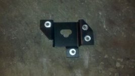
I am doing the prep work to MIG weld 14 gauge parking brake brackets to the underside of my mustang. In post 39 you said "use a letter A for all my plug welds". Are you referring to your voltage here? Is that what you use regardless of the metal thickness for plug welds. If so how do you choose your wire speed?
I was planning testing the settings for 14 gauge, starting on the thicker metal and then flicking down to the thinner metal and quickly returning to the thicker metal.
Thank you
Ivan
Ivan, your floor pans are likely a 19 or 18 gauge, so I would recommend putting the holes in the floor pan and weld through to the undrilled 14 ga brackets. You need sufficient heat to penetrate the thicker metal, and welding the other direction may have a tendency to burn through the thinner floor pan. This helps out also that you won't need to weld upside down from underneath with weld splatter falling on you. But you'll either need to clamp them in place or perhaps hold them up with a bottle jack or ???
The letter "A" is referring to the drill bit size, which is .234 diameter. I've heard of guys using as large as 5/16 or so in size for plug welds, but IMO that's a bit too large. I prefer to use smaller holes and more heat. With the smaller hole and adequate heat you should be able to just point and shoot at the center of the hole and let the wire feed fill it in. If your welder has a "suggested settings" chart, for welding to the 14 ga I would try the setting for about 1/8 thick, then bump up the wire speed SLIGHTLY from the recommended setting for 1/8". As with most welding operations, try some scraps of 14 and 18/19 firstto practice your welder settings and then do some el-destructo testing of pulling the pieces apart to see if the welds hold. Once you're happy with the results, move on to the good stuff on the car..
And if you haven't read this thread front to back, it's got some good info in it that may give you some other pointers to help out.
MP&C
Well-known member
The video below shows how I grind the welds. Where this shows dressing a plug weld, on a MIG welded **** weld seam it would be done similar in that each weld dot is planished, ground down to just above panel surface, and the final sanding will be done after the entire weld is complete to this stage. This helps to minimize the chance of thinning the panel from inadvertently hitting the parent metal on each side of the weld while sanding. If you sanded to flush after each weld dot, then you have a greater risk of removing parent metal and thinning the panel.
On the initial grinding, I use a cutoff wheel over something like a flap disc as the cutoff wheel has about the smallest contact patch you can get, for minimal heat buildup for less distortion introduced. It offers the best visibility to see where you are grinding to insure it happens on weld only and not to the sides on parent metal. Larger discs will obscure this view and you will be more likely to thin the panel from inadvertently sanding/grinding more than just the weld. Then once the weld is down to just above panel surface, I switch to a 3" sanding disc, about 80 grit, to final dress the area.
As with anything, there is more than one way to "skin the cat". No matter what the process in working sheetmetal, I try to use a method that limits any additional damage to the panel. No sense in adding more work than needed or adding damage to a panel that will dictate additional filler work. So if this process doesn't work for you to your satisfaction, experiment with others and choose the method that works best..
Last edited:
Racquetballguy
Member
- Joined
- May 16, 2014
- Messages
- 7
Robert - thanks for your reply. I am so used to referring to drill sizes as 3/8 or 1/2 I had forgotten there are other nomenclature systems. So let me apologize for wasting your time.
One of the parking brake brackets already has 1/4 inch plug holes in it so I will weld it upside down. I think setting and testing for 14 gauge and going fast over the 18/19 gauge will be better than setting for 18/19 gauge and hoping I anger enough penetration on the 14 gauge. Afraid to do circles on the 18/19 with the settings for 14 gauge so was thinking of starting on the 14 gauge and doing a kind of cross stitch pattern between the two, but fast on the 18/19.
Though I guess I could fill the holes and then weld from the top. Though it might be interesting to try thick to thin as it is something I have never done.
Great thread. Nice video.
Ivan
MP&C
Well-known member
Responses in blue
Be sure to post up some pics of your efforts when you get it done!
Robert - thanks for your reply. I am so used to referring to drill sizes as 3/8 or 1/2 I had forgotten there are other nomenclature systems. So let me apologize for wasting your time.
No apology needed. Any question is likely to answer the same one someone else had but is too much of a lurker to ask themselves.
One of the parking brake brackets already has 1/4 inch plug holes in it so I will weld it upside down. I think setting and testing for 14 gauge and going fast over the 18/19 gauge will be better than setting for 18/19 gauge and hoping I anger enough penetration on the 14 gauge.
Unfortunately, given the bracket's end use, you need a good penetration weld in both thicknesses of metal to get structural integrity. If you weld from the bottom and set the welder heat such that it doesn't blow through the floor pan, then more likely than not your weld to the 14 gauge is going to be a cold joint and is subject to failure. If it is hot enough for a good weld to the 14, it likely is going to blow a hole into the floor pan. I tend to worry more about the structural integrity of a good weld, especially a bracket used for a braking system, than anything else. IMO that is the priority here.
Afraid to do circles on the 18/19 with the settings for 14 gauge so was thinking of starting on the 14 gauge and doing a kind of cross stitch pattern between the two, but fast on the 18/19.
Though I guess I could fill the holes and then weld from the top. Though it might be interesting to try thick to thin as it is something I have never done.
Given the holes are already drilled, this would be my preference. Fill the holes in and dress them flat, then regroup with holes in the floor pan. Another analogy is when you perform a fillet weld between two unequal sized plates (sheet?) the MIG torch will be focused more on the thicker, with heat set for the thicker, that you will have good penetration on both. So to explain this further in what I had proposed earlier, the plug weld as applied from the top side of the floor pan would actually not touch the floor pan until the hole filled in. Aim the wire directly in the middle of the hole to establish the good weld penetration into the 14 ga first, and then as the hole fills in it will include the floor pan sheet metal into the weld, if that makes any sense. This way you get the heat on the thicker metal for good weld penetration, and the heat to the thinner metal is limited to the very end of the weld process. With a larger plug weld hole you would likely have to work your way around the hole perimeter in a circular motion, as you described. With a smaller hole like I use, the hole will have a tendency to fill in and meet the outer perimeter of the hole on its own. Again, practice this on some scraps before making a guinea pig of your good stuff. I don't like to commit to any process on good panels unless you've proven the method prior.
Great thread. Nice video.
Ivan
Be sure to post up some pics of your efforts when you get it done!
Racquetballguy
Member
- Joined
- May 16, 2014
- Messages
- 7
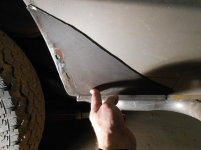
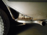
I am pleased with the way way the parking brake brackets turned out. Plug welding a 1/4 inch hole definitely required welding in a circular motion. I can see that a drill size "A" would have been perfect so that you can weld in the middle and let it fill in.
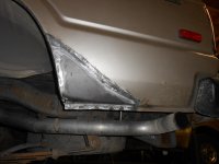
Maybe slight underpenetration in one of the welds, but not by much. The pictures show the beginning bracket and the back side of the welded on bracket. Pictures of the top of the weld didn't come out well.
Robert - Thanks for your help and all the great tutorials on this thread. Hope to see more.
Ivan
Attachments

alpinewhite
Well-known member
Robert, would this work for both .030" and .024" wire?I can see that a drill size "A" would have been perfect so that you can weld in the middle and let it fill in.
MP&C
Well-known member
I am pleased with the way way the parking brake brackets turned out. Plug welding a 1/4 inch hole definitely required welding in a circular motion. I can see that a drill size "A" would have been perfect so that you can weld in the middle and let it fill in.
Maybe slight underpenetration in one of the welds, but not by much. The pictures show the beginning bracket and the back side of the welded on bracket. Pictures of the top of the weld didn't come out well.
Robert - Thanks for your help and all the great tutorials on this thread. Hope to see more.
Ivan
Ivan, looks like that worked well for you. Looks good! Glad I could help.
Robert, would this work for both .030" and .024" wire?
I think it all boils down to having the wire feed speed set to fill the plug weld hole expeditiously, and enough heat to make that happen, just shy of wanting to blow a hole through. I use .035 ER70S-7 in mine, but then my machine does not like smaller wire. But if your machine does well with those wire sizes in the normal operations, I don't see any reason it shouldn't work with the smaller plug weld hole, just make sure you have plenty of heat. I always have tended to run my machine settings a little on the hot side, to insure good weld penetration, and this seems to help out in using the smaller hole. This is another of those instances to find some scraps and try it out. ......and then post up some pics to show the results that others may try it as well..

Thank you very much for the video. Your method looks great. Very Nice results. You are right about guessing with the flappy grinder. Its very hard to see what Your doing. I must invest in some air tools like Your using since i have a whole car to restore. Thx !
SteveH-CO
Well-known member
FJ62 rehab - rear quarter
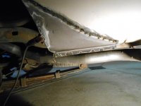
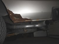
Reviving this thread. A few years back, I repaired probably 25 holes (1"-4" in diameter) in a 1980 FJ40 Land Cruiser, but I stumbled across this thread before I dove into repairing a 1989 FJ62 Land Cruiser.
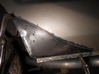
This thread reinforced some of what I knew, but gave me the confidence to replace bigger rusty sections, and introduced me to planishing the welds and more careful grinding, to minimize filler use. See photos. I used an almost rust-free patch panel from an Oregon truck and was very happy with the results. I liberally greased the back side and believe that it will survive the relatively mild Colorado climate, this time around.
The entire resto story is here:
http://www.tlca.org/trails/2014/0708/budget.shtml
Thanks to all you who have posted such detailed and quality photos on this site.
Steve
Reviving this thread. A few years back, I repaired probably 25 holes (1"-4" in diameter) in a 1980 FJ40 Land Cruiser, but I stumbled across this thread before I dove into repairing a 1989 FJ62 Land Cruiser.
This thread reinforced some of what I knew, but gave me the confidence to replace bigger rusty sections, and introduced me to planishing the welds and more careful grinding, to minimize filler use. See photos. I used an almost rust-free patch panel from an Oregon truck and was very happy with the results. I liberally greased the back side and believe that it will survive the relatively mild Colorado climate, this time around.
The entire resto story is here:
http://www.tlca.org/trails/2014/0708/budget.shtml
Thanks to all you who have posted such detailed and quality photos on this site.
Steve
Attachments

MP&C
Well-known member
Steve, nice results, thanks for sharing your work!
SteveH-CO
Well-known member
Thank you for the compliment.
Question for you, Robert: I have never had any warping problems with this kind of welding. From what you read here and elsewhere, you need to make a weld, and immediately slap a wet cloth on the area and keep things very cool. I simply make a few small tack welds, and by the time I have evaluated the high/low situation and fiddled around, everything is cool enough to make welds in between the first batch of welds. I continue along until it's all welded - not in a super hurry, but not consciously waiting for everything to cool, nor using a wet cloth. I'm I blessed/lucky/stupid?
On these Land Cruisers, the factory metal is usually 20 gauge, so it's not the beer-can thin metal on some newer vehicles - still, I would expect to see some warping, yet I haven't. I have used 18 ga. as my replacement metal, because it's what I had on hand.
48RON54
Well-known member
This is a great thread! I have been contemplating trying my hand at some metal/body work and this thread has really given me some motivation. My wife wiped out the entire side of my truck and it is nearing the end of its lifespan, so it is a perfect canvas for me to practice on IMO. I look forward to trying some of these tips out and will likely be asking lots of questions in the near future!
thanks again guys! this thread is great!
thanks again guys! this thread is great!
MP&C
Well-known member
Steve, how was your weld penetration on the back side, did you grind the welds on both sides?
sberry
Banned
I also do them different for repair. Some of these are rebuilding but I like to pull the patch in from behind about 3/32 or so, just a pinch so the weld absorbs it like a fused back up strip.
The light is poor here and the job isn't the greatest, my helper may have done some of this etc.
We grind the weld flush with the surface and scrape in a little bondo to level it. No holes come thru it.
The light is poor here and the job isn't the greatest, my helper may have done some of this etc.
We grind the weld flush with the surface and scrape in a little bondo to level it. No holes come thru it.
Attachments


Last edited:
SteveH-CO
Well-known member
Robert - to answer your question, I could not gain access to grind the welds on the backside (inside the quarter panel), and cosmetics don't matter there. My welds don't look as good from the back side as yours do, but seemed to show good penetration. I have learned (from this thread) to turn up the amps a bit and not be so afraid of blowing holes in the metal.
I presume that warping of the original panel is caused (only?) by excess heat? Can just the welding process apply stress (and warp) the body panel? If so, does planishing the welds help relieve that stress? I'd like to better understand the actual mechanics of why the panels warp, so I can stay ahead of this problem.
Thanks - Steve
jarhead
Well-known member
Robert - to answer your question, I could not gain access to grind the welds on the backside (inside the quarter panel), and cosmetics don't matter there. My welds don't look as good from the back side as yours do, but seemed to show good penetration. I have learned (from this thread) to turn up the amps a bit and not be so afraid of blowing holes in the metal.
I presume that warping of the original panel is caused (only?) by excess heat? Can just the welding process apply stress (and warp) the body panel? If so, does planishing the welds help relieve that stress? I'd like to better understand the actual mechanics of why the panels warp, so I can stay ahead of this problem.
Thanks - Steve
Yes, what he said...?
K13
Well-known member
Warping of the patch panel is a result of the weld shrinking as it cools. The weld then needs to be planished in order to stretch it back to its original configuration. This needs to be done gradually because you can over stretch and end up with the panel still being warped and then needing to be shrunk to return it to the proper configuration.
MP&C
Well-known member
Responses in blue
Adding a wet cloth to a newly applied weld does more harm than good. When someone tempers a piece of hot metal by dunking it in a pail of water, how exactly does this cooling effect help in a welding process? It doesn't. It makes the weld harder than it would be already, and shrinks just the same, regardless of the water applied. You did right by letting it cool on it's own.
It is not just the heat, but other factors as well. Inconsistencies in the processes will add to warping issues. Inconsistent starts and stops will show shrinking effects that parallel those actions. Using a tig, you'll see a slightly different "pull" on the panel in the center of a weld bead than you will at the ends. Similar effects as well with Mig, if you don't burn through in doing a weld pass. Varying, inconsistent gaps will require different amounts of filler and result in different amounts of heat introduced for a varying width HAZ, and deformity to match.
Comparatively, in most cases Mig welding will result in a bit more shrinking than other methods, specifically in using the dot welding as each dot as it shrinks will pull from all directions. This is why I suggest planishing each weld dot individually after it is placed, as it helps to stretch back out in all directions. Consistency in gaps, consistency in Mig weld dot sizing and overlaps, etc., planishing and grinding as you go, are what really help to reduce deformity in using the MIG. Now if doing a weld pass with the Tig, it should heat up gradually as you go across the panel and cool off in a similar fashion. So it has less of a tendency to pull from all sides, for an easier job of planishing to add that bit of stretch needed back in the panel.. Using a no-fill fusion weld with either Tig or O/A, with heat being controlled by the speed of torch travel, will introduce the least amount of heat into the panel, but more importantly, without the need to manually add filler, your speed is more consistent, your HAZ will be more consistent, so those shrinking effects from starting and stopping are virtually eliminated, for the least amount of distortion possible. So regardless of the process you choose, consistency in the process from start to finish helps out more than you realize. That includes panel fitup, it's all part of the weld process and affects the end results.
Thank you for the compliment.
No problem, well deserved!
Question for you, Robert: I have never had any warping problems with this kind of welding. From what you read here and elsewhere, you need to make a weld, and immediately slap a wet cloth on the area and keep things very cool. I simply make a few small tack welds, and by the time I have evaluated the high/low situation and fiddled around, everything is cool enough to make welds in between the first batch of welds. I continue along until it's all welded - not in a super hurry, but not consciously waiting for everything to cool, nor using a wet cloth. I'm I blessed/lucky/stupid?
Adding a wet cloth to a newly applied weld does more harm than good. When someone tempers a piece of hot metal by dunking it in a pail of water, how exactly does this cooling effect help in a welding process? It doesn't. It makes the weld harder than it would be already, and shrinks just the same, regardless of the water applied. You did right by letting it cool on it's own.
Robert - to answer your question, I could not gain access to grind the welds on the backside (inside the quarter panel), and cosmetics don't matter there. My welds don't look as good from the back side as yours do, but seemed to show good penetration. I have learned (from this thread) to turn up the amps a bit and not be so afraid of blowing holes in the metal.
Some are just skeered or misinformed. That's the one reason I set my old welder up for 3/16 steel and welded a 19 gauge practice coupon. To show that heat can be just as effectively controlled by trigger pull as turning down the heat. Those mud-dauber welds you see with no weld penetration are far more susceptible to failure and not worth the concern of trying to limit the heat in the panel. Always set up for full penetration welds first and foremost.
I presume that warping of the original panel is caused (only?) by excess heat? Can just the welding process apply stress (and warp) the body panel? If so, does planishing the welds help relieve that stress? I'd like to better understand the actual mechanics of why the panels warp, so I can stay ahead of this problem.
Thanks - Steve
It is not just the heat, but other factors as well. Inconsistencies in the processes will add to warping issues. Inconsistent starts and stops will show shrinking effects that parallel those actions. Using a tig, you'll see a slightly different "pull" on the panel in the center of a weld bead than you will at the ends. Similar effects as well with Mig, if you don't burn through in doing a weld pass. Varying, inconsistent gaps will require different amounts of filler and result in different amounts of heat introduced for a varying width HAZ, and deformity to match.
Comparatively, in most cases Mig welding will result in a bit more shrinking than other methods, specifically in using the dot welding as each dot as it shrinks will pull from all directions. This is why I suggest planishing each weld dot individually after it is placed, as it helps to stretch back out in all directions. Consistency in gaps, consistency in Mig weld dot sizing and overlaps, etc., planishing and grinding as you go, are what really help to reduce deformity in using the MIG. Now if doing a weld pass with the Tig, it should heat up gradually as you go across the panel and cool off in a similar fashion. So it has less of a tendency to pull from all sides, for an easier job of planishing to add that bit of stretch needed back in the panel.. Using a no-fill fusion weld with either Tig or O/A, with heat being controlled by the speed of torch travel, will introduce the least amount of heat into the panel, but more importantly, without the need to manually add filler, your speed is more consistent, your HAZ will be more consistent, so those shrinking effects from starting and stopping are virtually eliminated, for the least amount of distortion possible. So regardless of the process you choose, consistency in the process from start to finish helps out more than you realize. That includes panel fitup, it's all part of the weld process and affects the end results.
Last edited:
steveo3002
Well-known member
any words of wisdom for welding trim holes that about pencil size ?
and great work , very impressive
and great work , very impressive
classicJackets
Well-known member
Dodge, What I understand planishing as is using a dolly and hammer to make sure that any shrinking is opposed by beating the weld back to flat. What I don't know is whether that's supposed to be done "behind" the weld surface or on top. There are several clips on Youtube and articles but I couldn't get a feel for the process enough from those videos.
Hopefully Robert will pop back in and straighten us both out on the matter. Thanks, Robert!
Hopefully Robert will pop back in and straighten us both out on the matter. Thanks, Robert!
SteveH-CO
Well-known member
Thanks Robert - your blue-text reply was very helpful. This statement:
To show that heat can be just as effectively controlled by trigger pull as turning down the heat.
is what took me years to figure out. That the voltage knob on the Miller 175 is only part of what determines penetration or burn through. Trigger time is the other half. I suspect that novice welders run the voltage too low, due to fear of burning through. I surely did. I run the welder hotter now, and just don't hold the trigger as long.
One day, the back-side of my welds will look as good as yours! (The back side of Robert's welds look better than the front side of most people's welds)
MP&C
Well-known member
Responses in blue...
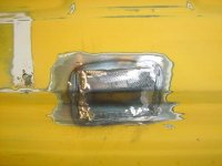
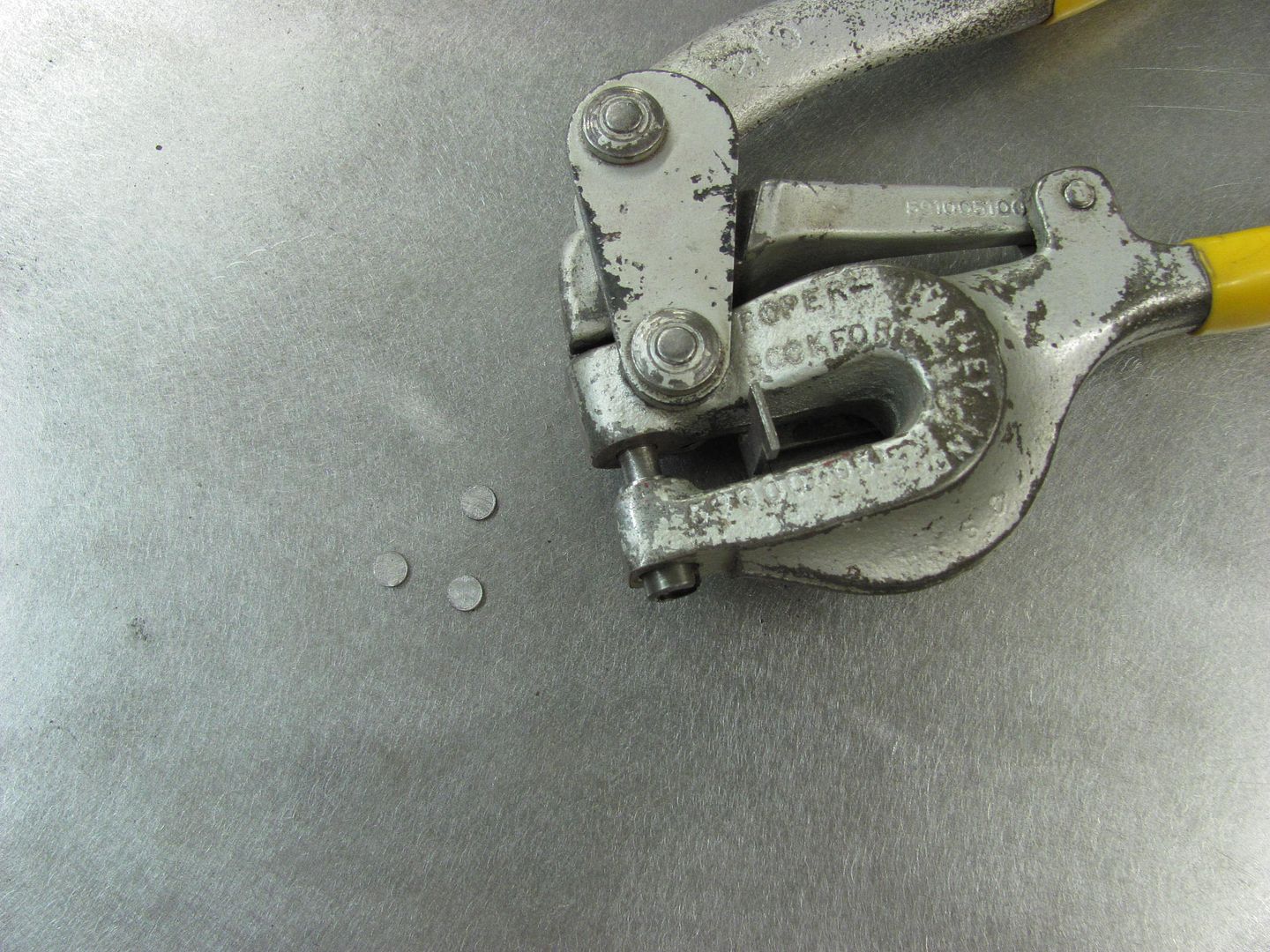
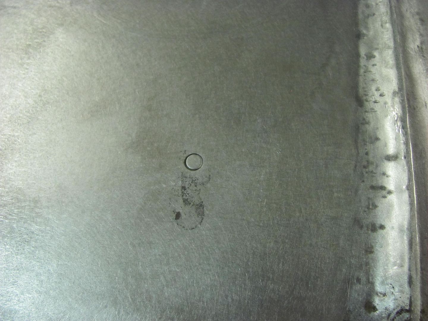
For anything much bigger than 3/16" in diameter I prefer to cut a plug and weld it in as opposed to trying to weld all that closed. The effect of a Mig weld being slightly harder than the parent metal also comes into play with weld blob upon weld blob. The second weld will make the first one a bit harder, making it more difficult to planish, grind, etc. I typically use my Roper Whitney hand punch to make some plugs for the holes, but the punch part has the locating center point, which will tend to distort the plugs. On the example below, I found the correct size and ground off the point.
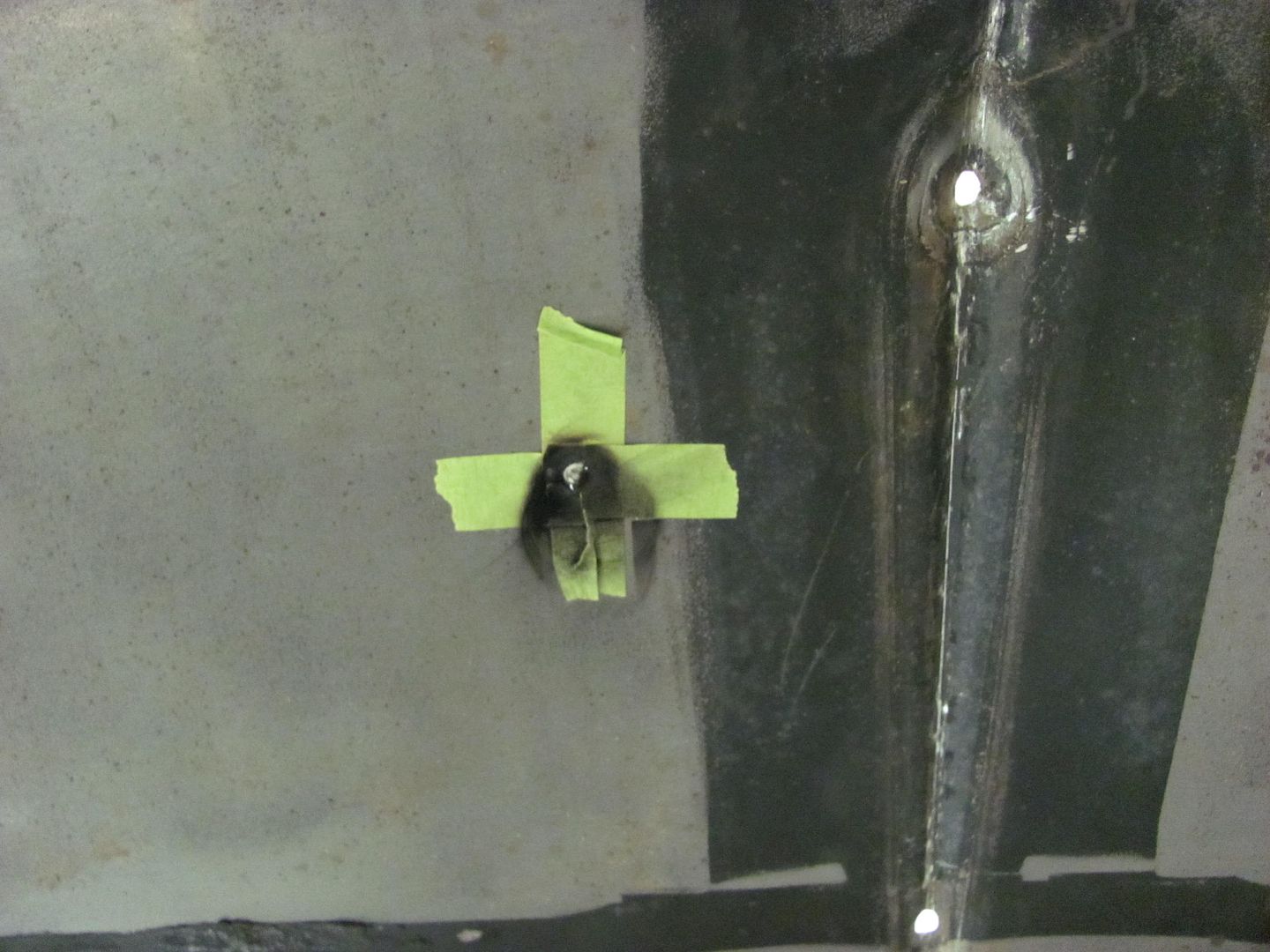
Plug held in place with a couple strips of tape on the bottom, long enough to tack in place....
Welded in place and welds dressed....
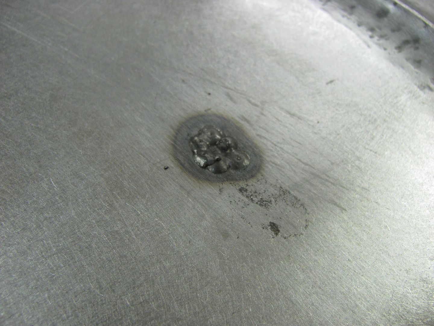
No fuss, no muss. Where some will opt to use a copper backing spoon and fill until the hole is gone, IMO you are introducing too much heat and the blob theory explained above is also playing on the hardness factor of the area. Call it personal preference if you will, but I think you'll see better results using sheet metal plugs...
IMO anything done to speed up the cooling process in welding is equivalent to quenching to some degree, which could add hardness unnecessarily. The only time I've seen a need to cool a panel is when torch or disc shrinking, which has less of a hardening effect as the temps of the panel are no where near the superheated temps seen while welding. In that case, cooling is done more to speed up the process of reading the panel for the next shrink. Left to cool on it's own would add considerable time to the torch shrinking process, as we would have to wait for the panel to cool down as the heating will temporarily cause a bulge in the panel. But for welding, I use a systematic process in welding patch panels that doesn't really call for any artificial cooling. Let me use some pictorials to explain a bit better.
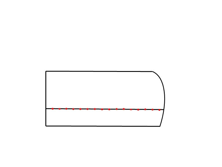
Let's say we are installing a lower door skin to repair some rust. The repair panel has been trimmed for zero gap, and the panel is tacked on, starting at one end, and working progressively toward the other. Don't skip around from one end to the other as you have a greater chance of misalignment in that you may have more metal on one side than the other, which will result in a buckle from the excess metal on the one side. Start at one end, tack, move a cuppatree inches, align the panels together, make another tack, repeat. This insures the panels are correctly aligned as you work progressively from one side to the other.
Once done with the last tack, go back to the beginning and use a hammer and dolly to planish each weld dot, working in the same start to finish pattern. Now go back to the beginning and use the 3" cutoff wheel to grind the weld dots down to just above flush, both FRONT AND BACK, as this gets the weld prouds out of the way for planishing the next sets of weld dots, and also removes all the excess weld that an additional weld on top of the last would cause extra hardening effect, as described above in the blob theory. I grind to just above panel height for a weld seam like this, and final cleanup with a 3" roloc sander will be used at the end to dress the seam to the parent metal. Here's a video that shows the grinding process, but as this is a plug weld it is dressed immediately following.
https://www.youtube.com/watch?v=V2WHT_zMOE8
Now that those welds are down and out of the way, let's add the next set. Here I'll overlap the last set of welds by about 1/3 to 1/2. Whatever the distance of your overlap, keep it consistent throughout.

This method helps to eliminate any missed areas like what may occur if you kept skipping around. Again, start from the same spot you did before, overlap the first weld dot done, go the the next, overlap, repeat, until you get to the end. Then go back and repeat the planish from start to finish, then grind weld dots from start to finish, both FRONT AND BACK, and then repeat the overlap process again. Keep repeating the process until the weld seam has been finished, then use a roloc sander to dress the little bit of remaining weld to flush with parent metal, both front and back side.
If this sounds like a slow, monotonous process, that is the intent. This promotes consistency in the welding process, from fitup through to final welds dressed. At no point is it necessary to cool the welds, by the time planishing and grinding are complete, the welds on the panel are plenty cool to the touch. Any artificial cooling serves no purpose.
Planishing per Ron Covell is to flatten or straighten out a bumpy panel (if I remember that correctly). As it applies to metal shaping, one would use a blocking hammer and a shot bag to add shape to a panel, but once complete it would appear as if it had walnuts all across the surface of the metal. A planishing operation would smooth these out to a more consistent "flat" finish (where flat means the panel has some crown to it, but no more lumps). As it applies to welds, planishing is the use of a hammer and dolly (or other appropriate devices as the job dictates) to add some stretch back into the weld and HAZ for the purpose of negating any of the shrink that has occurred. I would add that seldom will you get it perfect the first time as you go through the weld process as described above. You will always have a bit of planishing to complete after the welds have been dressed out, or even some shrinking if you got too carried away in spots.
any words of wisdom for welding trim holes that about pencil size ?
For anything much bigger than 3/16" in diameter I prefer to cut a plug and weld it in as opposed to trying to weld all that closed. The effect of a Mig weld being slightly harder than the parent metal also comes into play with weld blob upon weld blob. The second weld will make the first one a bit harder, making it more difficult to planish, grind, etc. I typically use my Roper Whitney hand punch to make some plugs for the holes, but the punch part has the locating center point, which will tend to distort the plugs. On the example below, I found the correct size and ground off the point.
Plug held in place with a couple strips of tape on the bottom, long enough to tack in place....
Welded in place and welds dressed....
No fuss, no muss. Where some will opt to use a copper backing spoon and fill until the hole is gone, IMO you are introducing too much heat and the blob theory explained above is also playing on the hardness factor of the area. Call it personal preference if you will, but I think you'll see better results using sheet metal plugs...
Robert: What do you think of compressed air to cool the weld? I have heard of that being used. Also, could you explain "planishing" the weld?
IMO anything done to speed up the cooling process in welding is equivalent to quenching to some degree, which could add hardness unnecessarily. The only time I've seen a need to cool a panel is when torch or disc shrinking, which has less of a hardening effect as the temps of the panel are no where near the superheated temps seen while welding. In that case, cooling is done more to speed up the process of reading the panel for the next shrink. Left to cool on it's own would add considerable time to the torch shrinking process, as we would have to wait for the panel to cool down as the heating will temporarily cause a bulge in the panel. But for welding, I use a systematic process in welding patch panels that doesn't really call for any artificial cooling. Let me use some pictorials to explain a bit better.
Let's say we are installing a lower door skin to repair some rust. The repair panel has been trimmed for zero gap, and the panel is tacked on, starting at one end, and working progressively toward the other. Don't skip around from one end to the other as you have a greater chance of misalignment in that you may have more metal on one side than the other, which will result in a buckle from the excess metal on the one side. Start at one end, tack, move a cuppatree inches, align the panels together, make another tack, repeat. This insures the panels are correctly aligned as you work progressively from one side to the other.
Once done with the last tack, go back to the beginning and use a hammer and dolly to planish each weld dot, working in the same start to finish pattern. Now go back to the beginning and use the 3" cutoff wheel to grind the weld dots down to just above flush, both FRONT AND BACK, as this gets the weld prouds out of the way for planishing the next sets of weld dots, and also removes all the excess weld that an additional weld on top of the last would cause extra hardening effect, as described above in the blob theory. I grind to just above panel height for a weld seam like this, and final cleanup with a 3" roloc sander will be used at the end to dress the seam to the parent metal. Here's a video that shows the grinding process, but as this is a plug weld it is dressed immediately following.
https://www.youtube.com/watch?v=V2WHT_zMOE8
Now that those welds are down and out of the way, let's add the next set. Here I'll overlap the last set of welds by about 1/3 to 1/2. Whatever the distance of your overlap, keep it consistent throughout.
This method helps to eliminate any missed areas like what may occur if you kept skipping around. Again, start from the same spot you did before, overlap the first weld dot done, go the the next, overlap, repeat, until you get to the end. Then go back and repeat the planish from start to finish, then grind weld dots from start to finish, both FRONT AND BACK, and then repeat the overlap process again. Keep repeating the process until the weld seam has been finished, then use a roloc sander to dress the little bit of remaining weld to flush with parent metal, both front and back side.
If this sounds like a slow, monotonous process, that is the intent. This promotes consistency in the welding process, from fitup through to final welds dressed. At no point is it necessary to cool the welds, by the time planishing and grinding are complete, the welds on the panel are plenty cool to the touch. Any artificial cooling serves no purpose.
Planishing per Ron Covell is to flatten or straighten out a bumpy panel (if I remember that correctly). As it applies to metal shaping, one would use a blocking hammer and a shot bag to add shape to a panel, but once complete it would appear as if it had walnuts all across the surface of the metal. A planishing operation would smooth these out to a more consistent "flat" finish (where flat means the panel has some crown to it, but no more lumps). As it applies to welds, planishing is the use of a hammer and dolly (or other appropriate devices as the job dictates) to add some stretch back into the weld and HAZ for the purpose of negating any of the shrink that has occurred. I would add that seldom will you get it perfect the first time as you go through the weld process as described above. You will always have a bit of planishing to complete after the welds have been dressed out, or even some shrinking if you got too carried away in spots.
Last edited:
Justanoldguy
Well-known member
Thanks MP&C.
Best thread for advise I've ever seen.
Cheers
Clive.
.
Best thread for advise I've ever seen.
Cheers
Clive.
.
Last edited:
jeepinerdeep
Well-known member
Thanks MP&C.
Best thread for advise I've ever seen.
Cheers
Clive.
.
Just like therapy, only better because its extremely useful.
Mad props to MP&C, it's not often that someone knows their craft, can articulate it well and is willing to share.
MP&C
Well-known member
Thanks for the comments guys, glad to help out...
msh-r
Member
Finally read this entire thread; what a wealth of knowledge in here, thanks! Definitely will be using this for reference when I get started on my Mustang project.
1971gsfan
Well-known member
Robert
Thanks for explaining, very informative. I'm still trying to get my heat/trigger time right to make this type of repair. thicker metals are no problem but these body panels are giving me a fit with blow through. This definitely takes some practice. Like the guys said you have Mad Skills
Thanks for explaining, very informative.
I'm still trying to get my heat/trigger time right to make this type of repair. thicker metals are no problem but these body panels are giving me a fit with blow through. This definitely takes some practice. Like the guys said you have Mad Skillsdlcwent
Member Emeritus
Awesome thread. MP & C thanks for all your input. Very helpful for anyone needing technique. I have done my share of welding in rockers, cab corners, and patches. And can again add.. You can learn something new everyday.
IMO anything done to speed up the cooling process in welding is equivalent to tempering to some degree, which would add hardness unnecessarily. The only time I've seen a need to cool a panel is when torch or disc shrinking, which has less of a hardening effect as the temps of the panel are no where near the superheated temps seen while welding. In that case, cooling is done more to speed up the process of reading the panel for the next shrink. Left to cool on it's own would add considerable time to the torch shrinking process, as we would have to wait for the panel to cool down as the heating will temporarily cause a bulge in the panel. But for welding, I use a systematic process in welding patch panels that doesn't really call for any artificial cooling.
Small technical correction/clarification.
'Rapidly' cooling a very hot metal (steel, in our case here) is called quenching.
A controlled reheating (typically to a much lower temperature than we were dealing with in the quenching step above) and then coolling again (could be 'fast' or 'slow' cooling, and it could possibly involve multiple reheat and recool steps, possibly to varying time/temperature profiles) is called tempering.
Some steels are quenched in water (alloy W-1, for instance), others in oil (alloy O-1), others in air (alloy A-7).
Quenching and tempering are only some of the possible operations in heat treating.
The hardening effect of quenching on steel alloys depends mostly (but not solely) on the carbon content.
Below about 0.20 % (yes, that is correct, just one fifth of one percent) carbon content in the steel alloy, and the steel typically does not appreciably harden (or strengthen either) if heated and quenched.
So typical 1018 or 1020 low-carbon steel does not harden if heated and quenched.
But welding filler alloys are typically not low carbon steel. The filler may be 'low carbon' (and often is, except for certain high-alloy fillers), but there are other included alloying ingredients in the filler that make it into a NOT low carbon steel.
Those other alloying ingredients (such as silicon, manganese, and molybdenum, among others) in the steel alloy (the weld filler, in this discussion) DO tend to make the resultant steel weld bead stronger and harder than "plain" low carbon steels.
Thus, while 1020 steel may have a tensile strength of approximately 55 ksi (hot rolled) to 60 ksi (cold rolled), a typical welding electrode used for mild steel welding will have a tensile strength of 60-70 ksi (6010 SMAW electrode has a 60 ksi tensile strength minimum spec, while 7018 SMAW or ER70S-6 GMAW/GTAW has a 70 ksi tensile strength minimum spec).
Just a (technical) FYI.
Oh, and another Thanks to Robert for taking the time and effort to show and explain a whole lot of the work that he does.

MP&C
Well-known member
Thanks for clarifying!
I love the idea of planishing the welds what can be done guys (escpecially you MP&C) if you are welding something like a rocker where you do not have access to the backside to planish with a dolly. I am doing just rocker faces and this worries me and I do not want to use filler. I dont want warping to occur but there is no access from the back.
MP&C
Well-known member
Welcome to the site Dave!
You have a few choices in this, you could cut an access hole in the inner rocker to provide access for hammer and dolly from the back side, then re-weld the access "patch". I will say that seldom is the rust within a rocker cavity limited to one small area, so this may also help to expand your access for a more thorough inspection.
Next, the process used may help to limit any damage. As explained in this thread, repeated starting and stopping in the welding process likely adds the most distortion possible. If you can fit and trim your panels tightly enough to perform a no-fill fusion weld (Tig or O/A gas) then this will do the most to limit any distortion to the panel from a continuous weld seam around the patch. In most cases, it still needs some minor planishing, but the no-fill fusion weld processes should realize the least amount of distortion.
In many high end restorations, panels such as hood skins, door skins, etc. will be removed to insure there is no rust lurking between panels, and then once any repairs are complete the panels will be welded back together. So it's possible to drill out the spot welds and remove the rocker altogether, fix any rust issues with full access to the rear side for planishing, then reinstall. This also provides the best opportunity for rust preventative measures, such as a good epoxy coating on the internal surfaces, prior to welding into place.
Last option, and I'm assuming you're working on an AMC project based on screen name, is to purchase or absent availability, fabricate a new rocker panel.. Most panels such as this are held on with spot welds, which if done in the factory locations will also provide much less distortion than a full perimeter weld that one performs on a patch installation..
Robert,I have always followed your threads,because you explain things in easy to understand terms and I like simple. When you planish your weld dots,how hard and how long do you hammer? You may have already explained that and I've missed it,if so ,sorry.
As a side note,how many hours of metal work will you have in the 55 wagon?
Thanks for the help. Your t-shirts got a lot of nice compliments at the "Back to the 50's" rod run last summer,
Mike
As a side note,how many hours of metal work will you have in the 55 wagon?
Thanks for the help. Your t-shirts got a lot of nice compliments at the "Back to the 50's" rod run last summer,
Mike