Well I guess it's about time for a sequel. I had a left over door from a bus repair earlier this year, and as it was damaged the least, we thought to keep it as a starting point. New ones in primer go for just under 1K, so I think we can save some money here....
The last time I used the "donut dolly" was with the low crown body hammer (the flat one) but when I tried it on this flat panel, progress seemed to be rather slow. I think the low crown hammer was better matched to a crowned panel, and with this panel being flat, I may have better luck with a crowned face body hammer. So as we're starting with bent metal anyhow, what's a little trial and error going to hurt? I'll just keep my fingers crossed that the hammering force would not be great enough to pound dents in the other direction. (we're looking for consistency and moderation
")
)
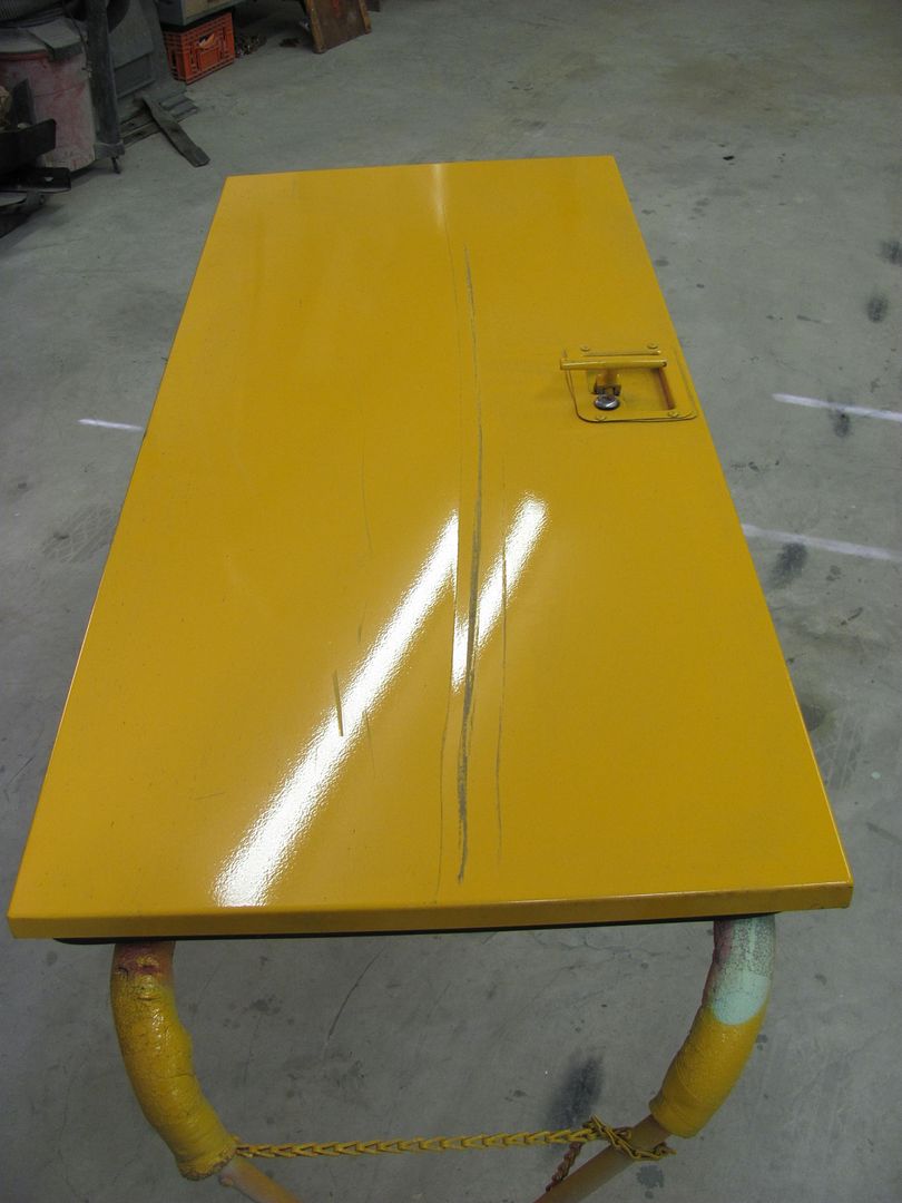
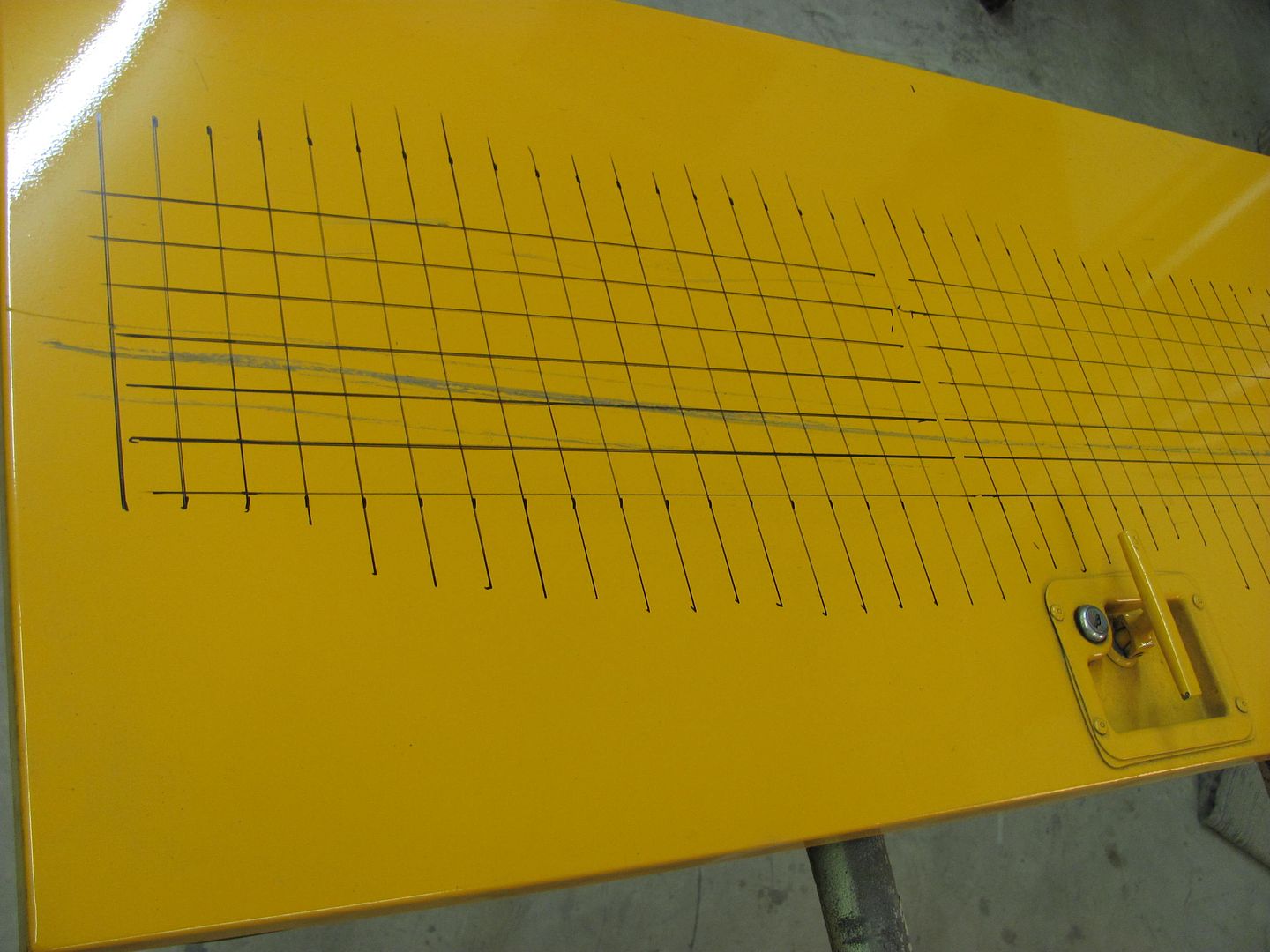
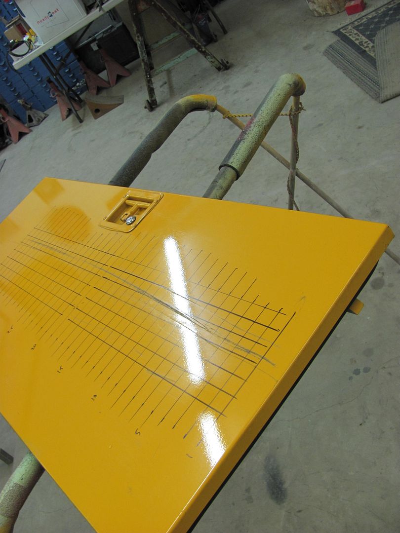
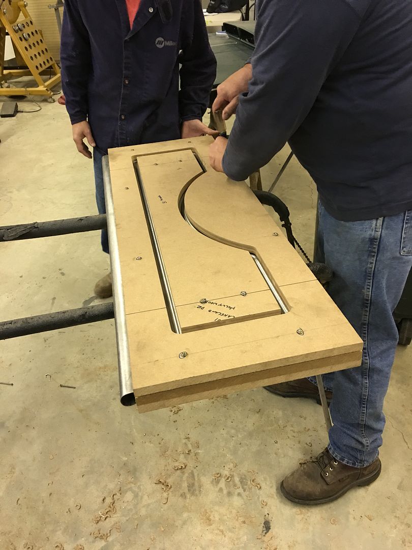
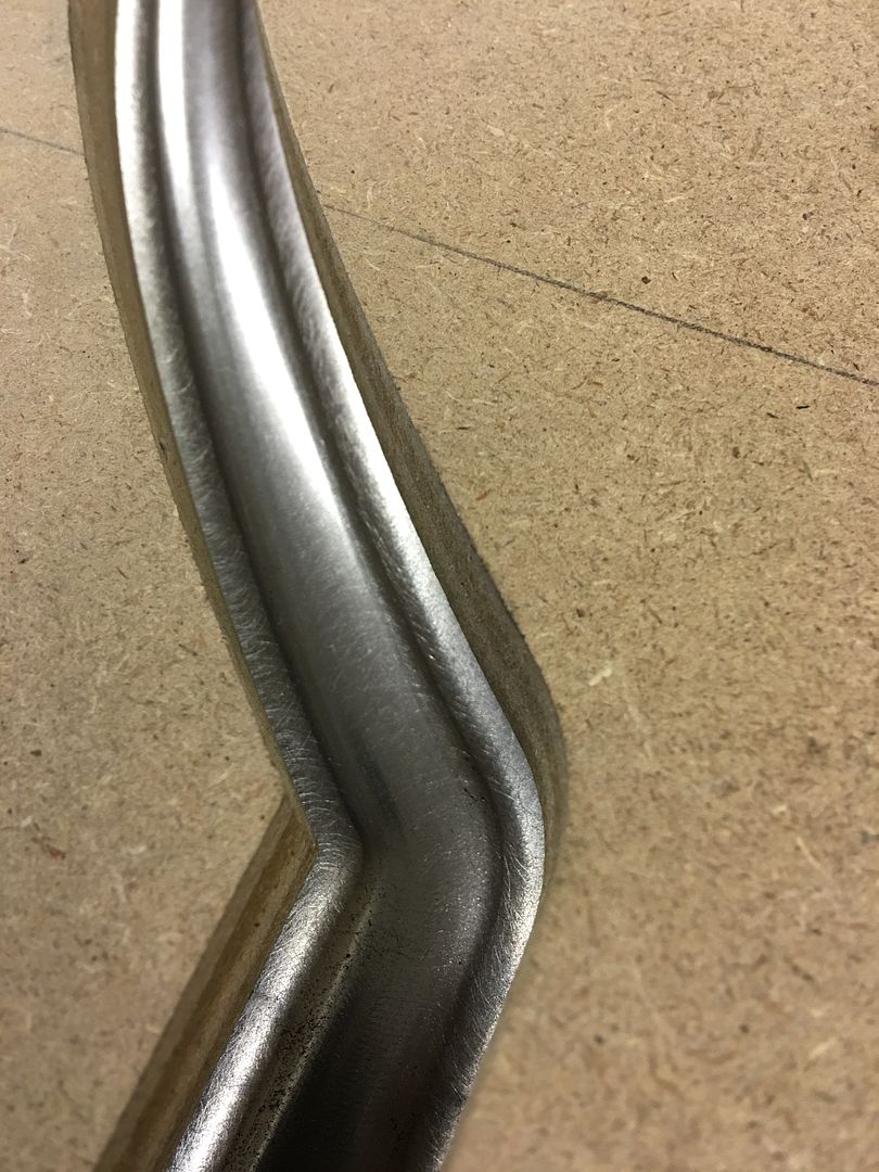
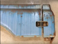
Here's our dented sample today, an aluminum door skin with a nice crease that travels just about the full length of the door.
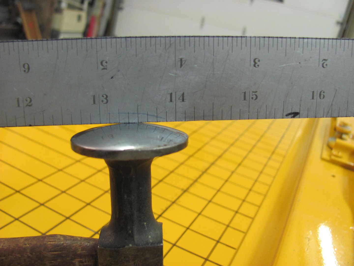
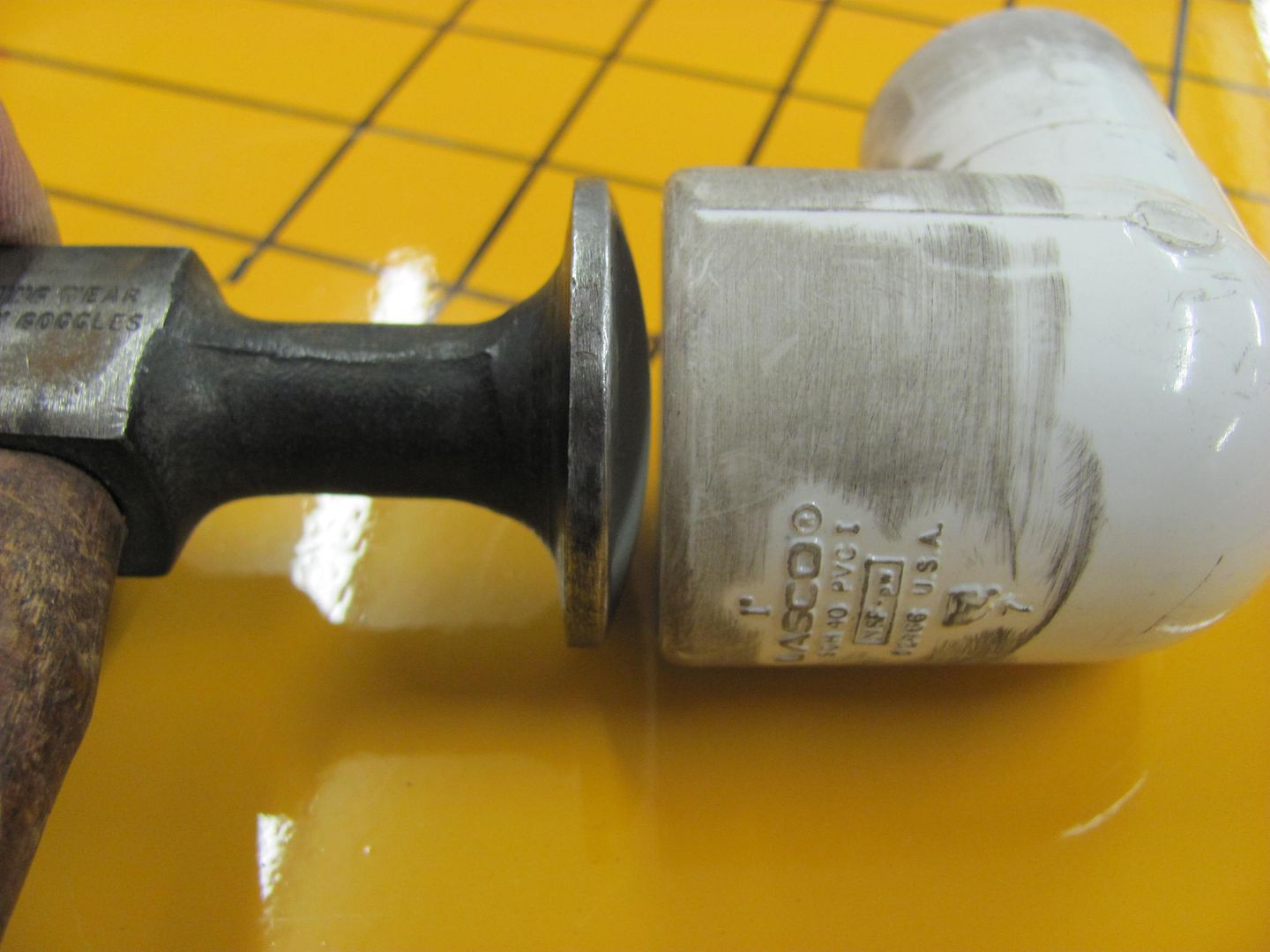
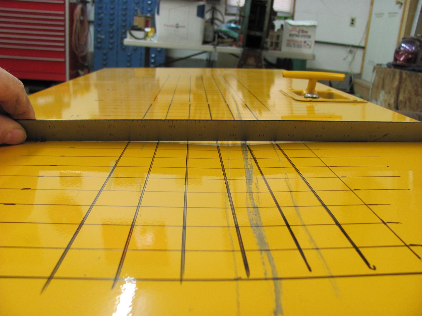
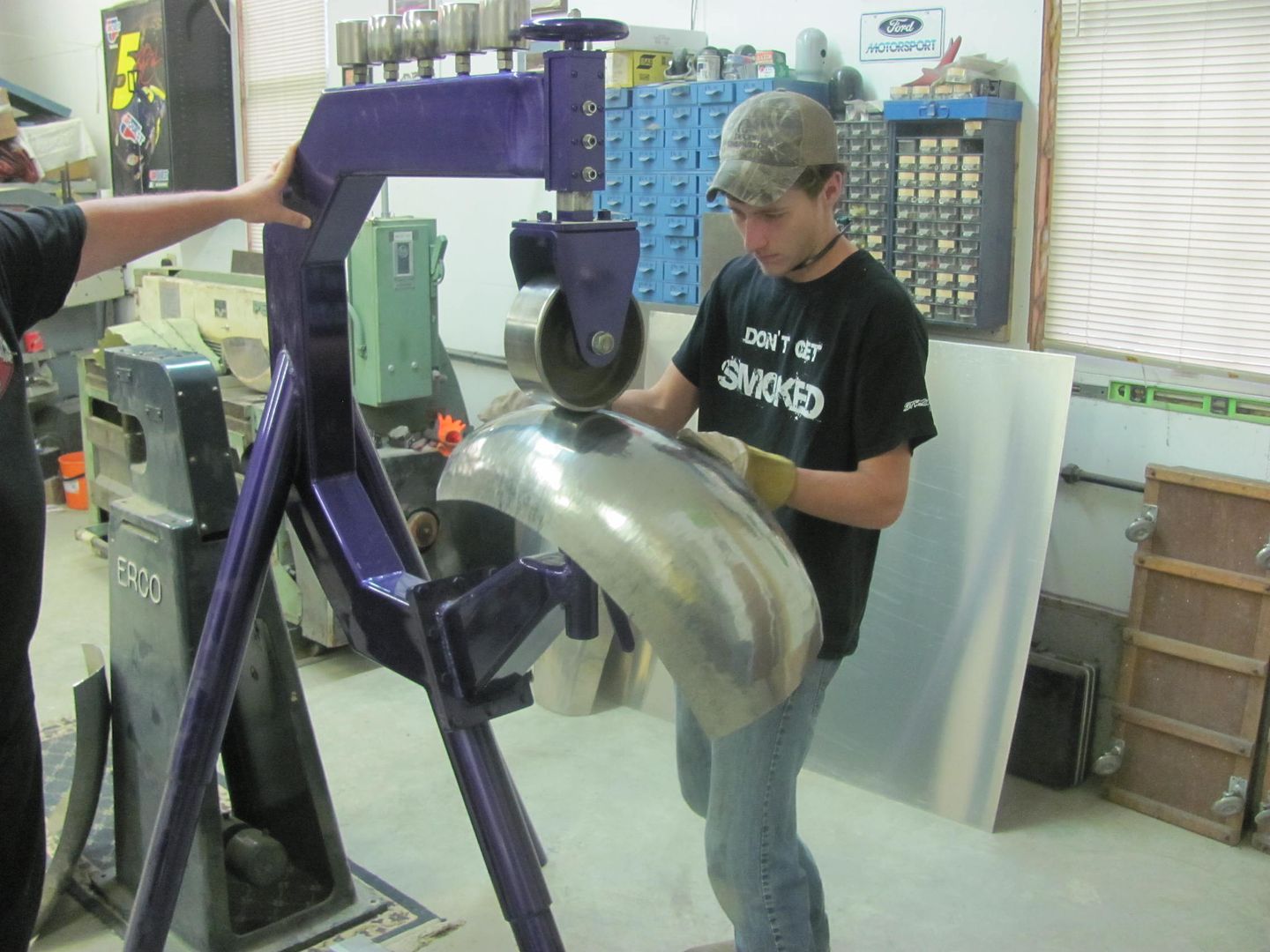
As the donut dolly is very closely matched in size to the hammer diameter, accuracy in locating the devices opposite each other is crucial. Depending on the panel you are repairing, this may be a challenge in itself. To keep the tools properly aligned and thus provide a more efficient shrink, I suggest a grid on either side, matched to identical starting points.
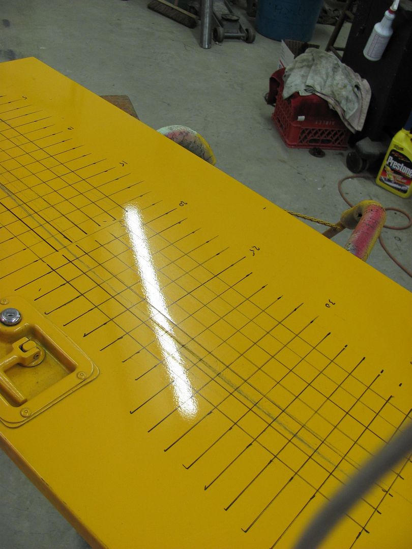
I numbered every fifth one just to keep better track of where I was. Some days you need all the help you can get. Also shown is the damage before starting, located at grid 5, 10, and 15, just for reference of our progress.
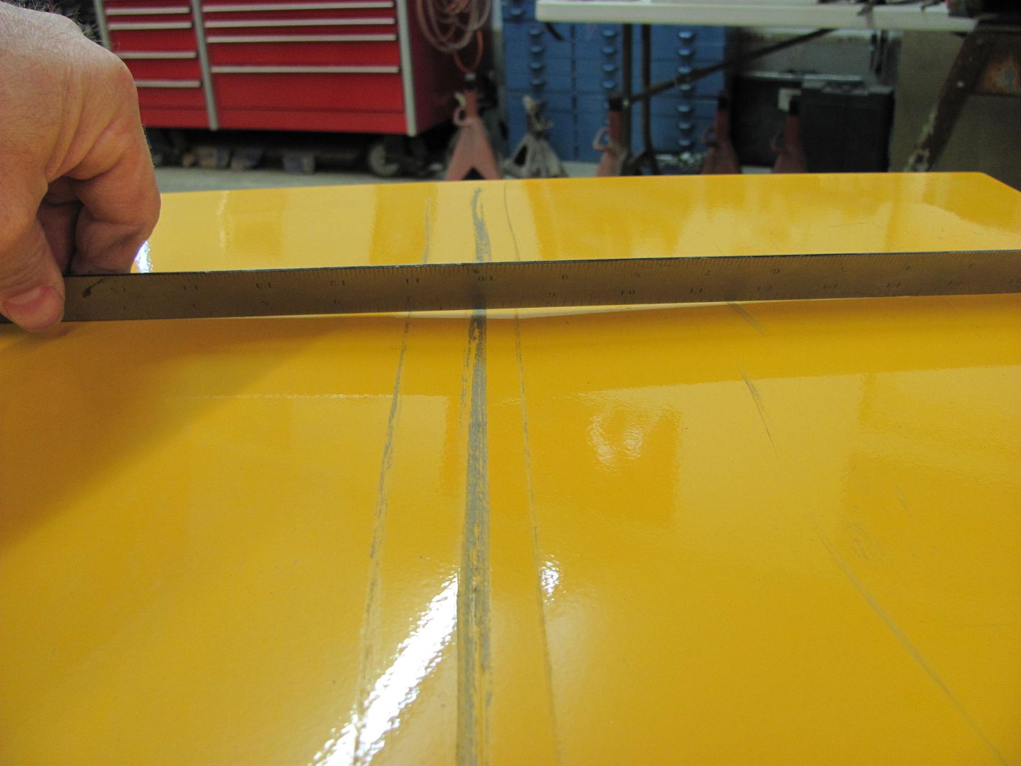
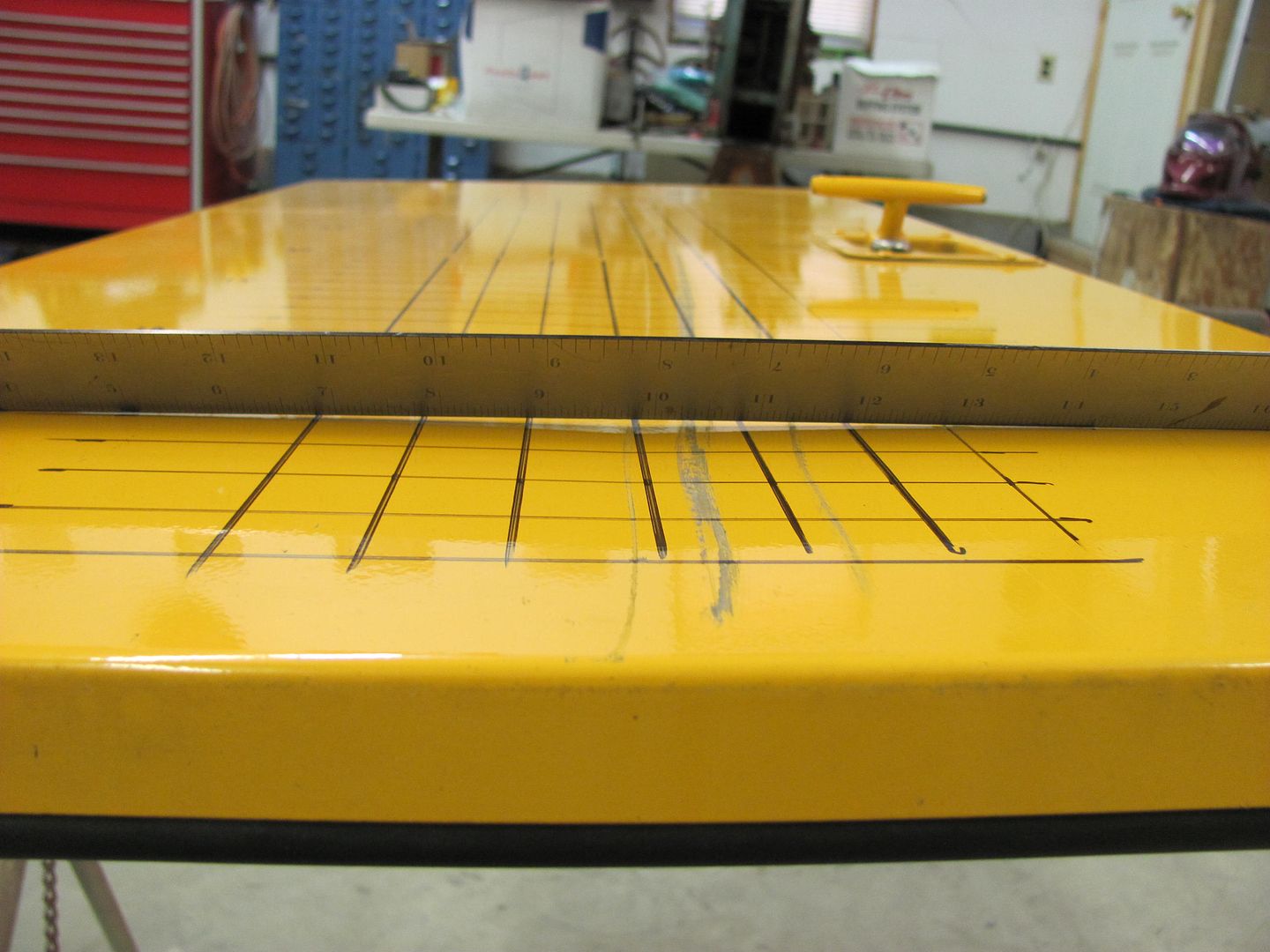
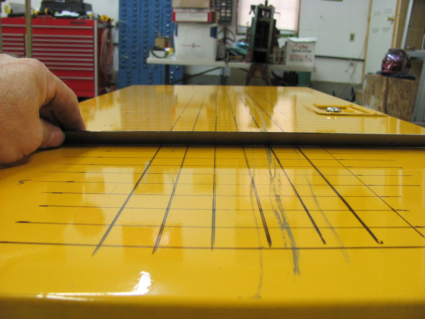
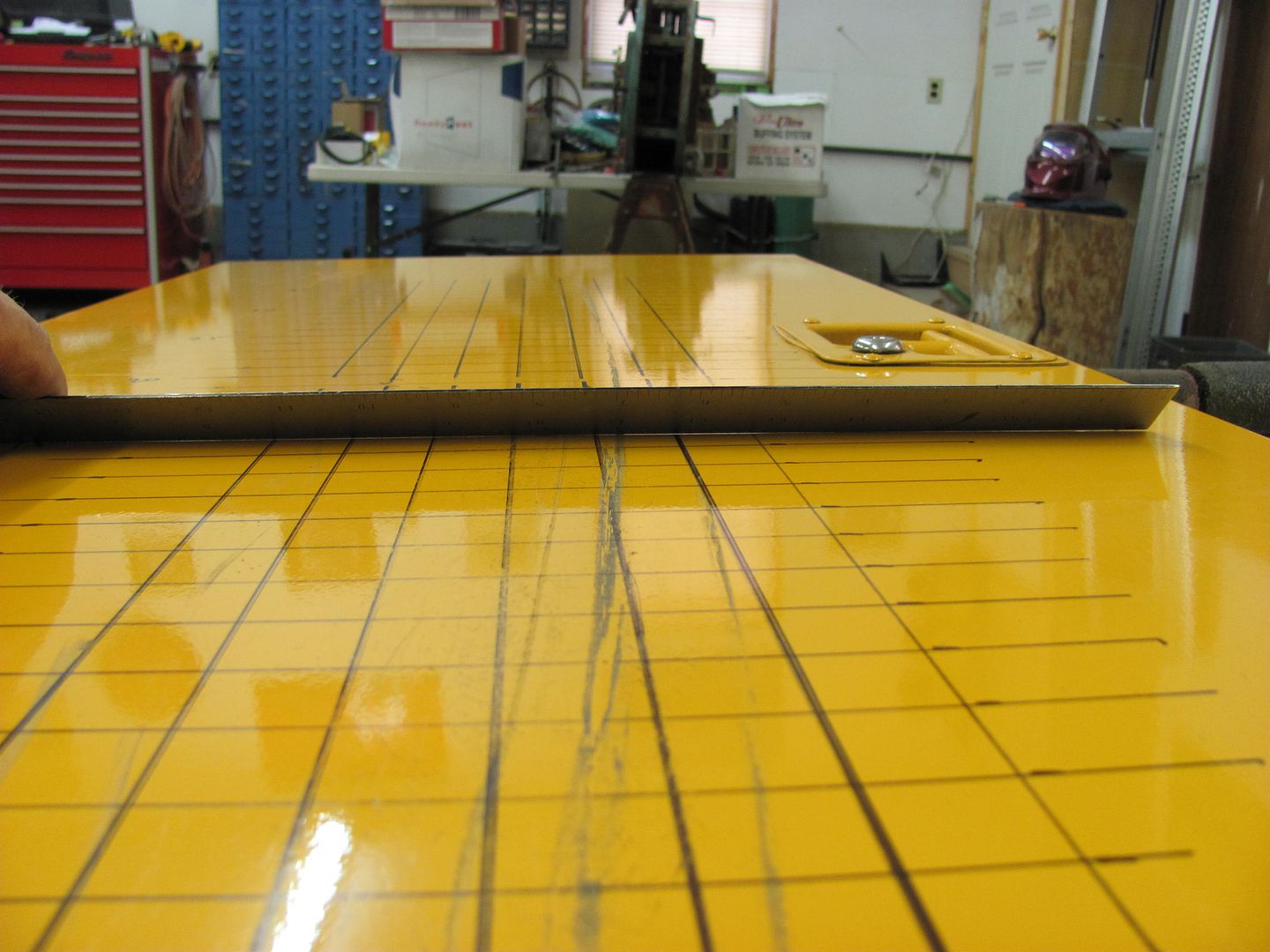
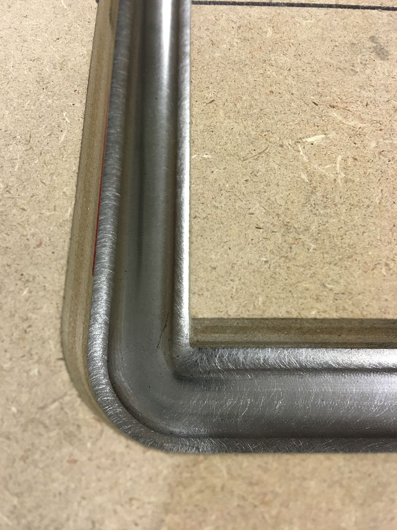
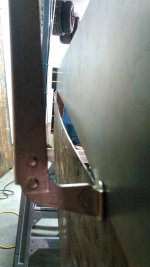
As I am working with a flat panel, I am able to use a straight edge to monitor the progress and see where additional shrinking may be needed. If you are using this process on a crowned panel, I would suggest making a profile template matched to the undamaged side of the car. Also, seldom does the crown on a panel remain consistent from one end of the panel to another, so it is very possible you may need different profile templates to accurately guage different sections along the panel.
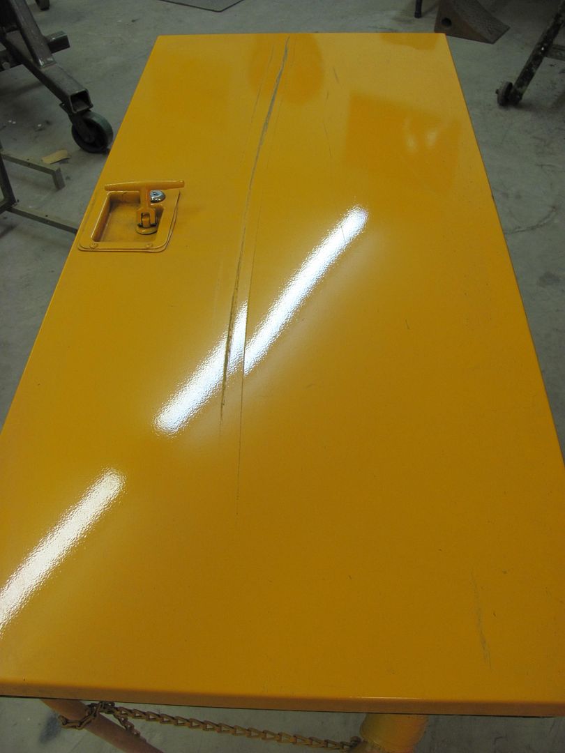
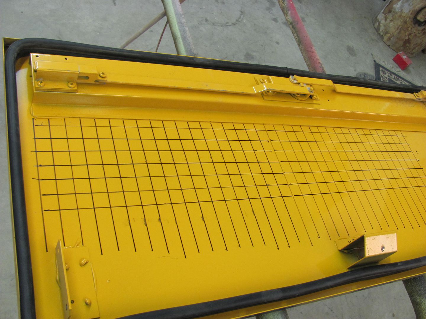
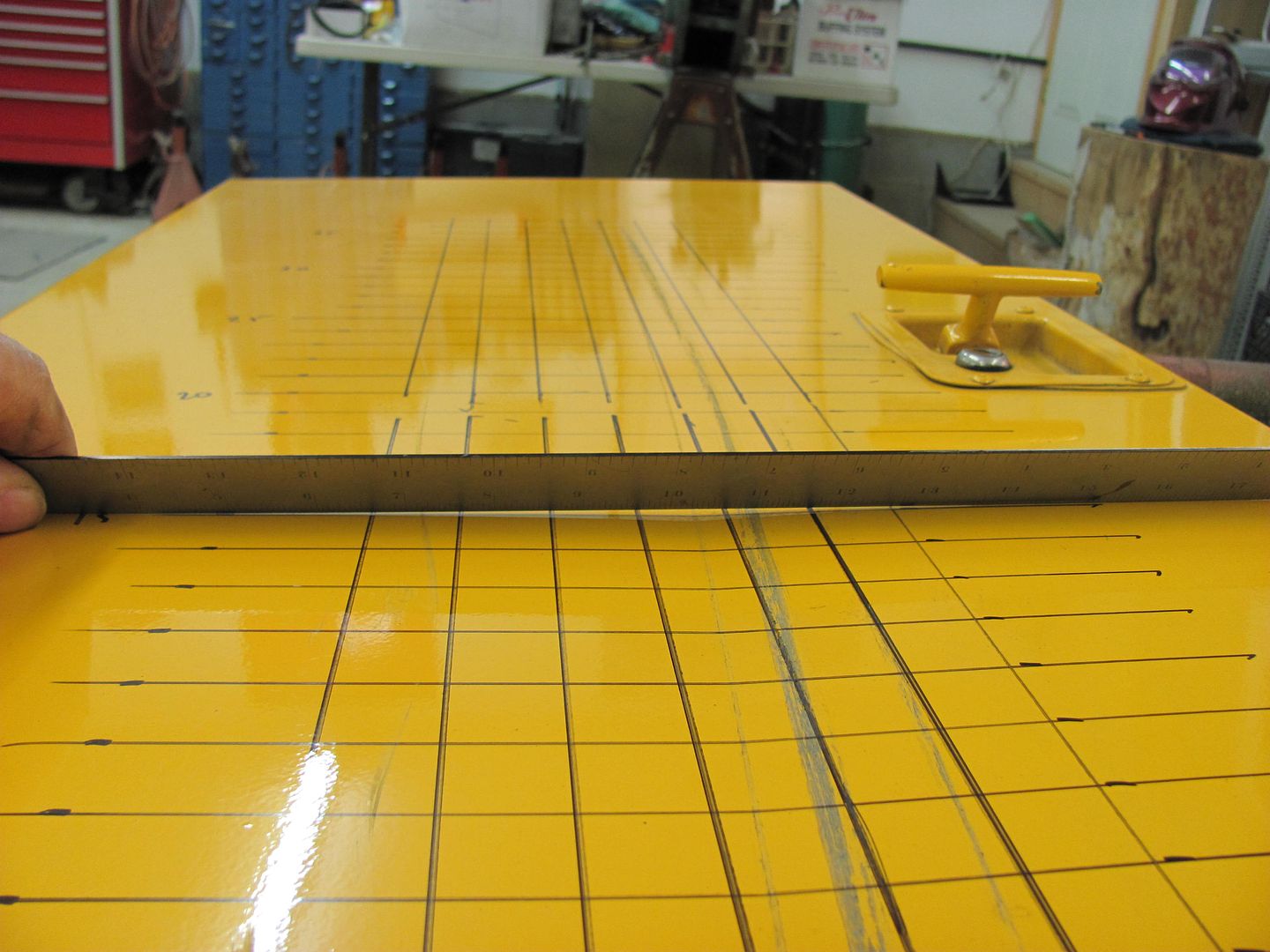
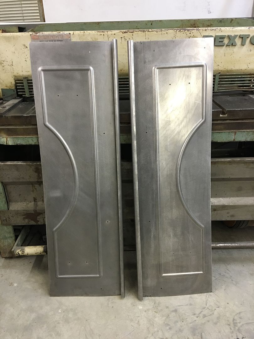
After about 30 minutes of work, here are the results, again located at grid 5, 10, and 15.
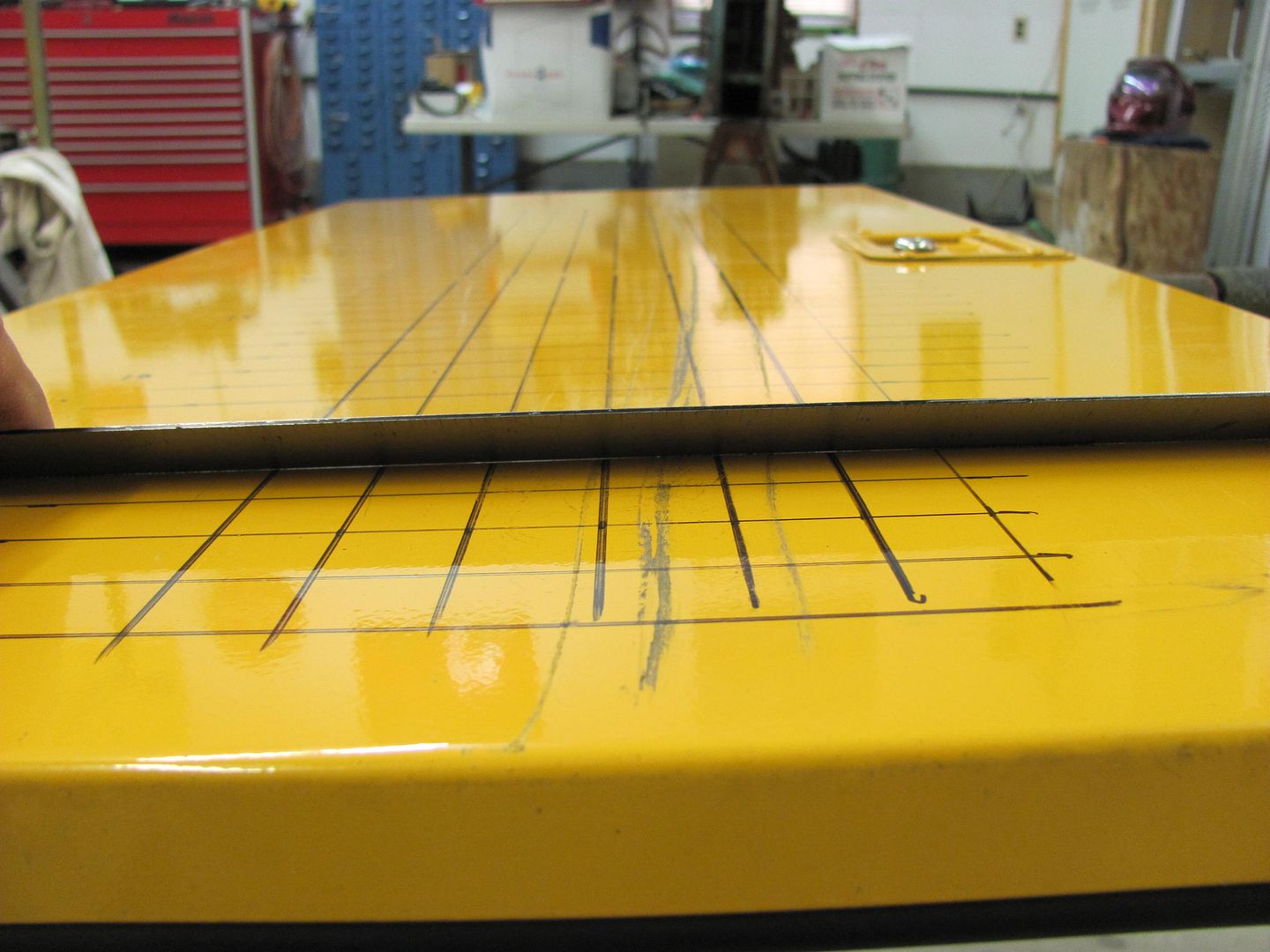
And the light reflection shows considerable improvement over the first pictures....
This is now at a point we could strip the paint off the door, and any remaining defects would be taken care of with high build primer.


 Mark, if you could find a local Kiwi to show you some O/A welding, then you'll get rid of the Mig headaches..


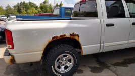


 , but 1 rocker has a few bubbles