To avoid these ads, REGISTER NOW!

Welding positioner shop built

isb cornbinder

Well-known member
Joined
Nov 3, 2010
Messages
7,073
Location
Pacific South West, BC, Canada
I did ask my wife if I could use her tread-mill. What happened may not have been what she thought my intent may have been.
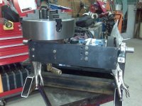
I took the drive motor and electronic controls to drive the rotation of the positioner. I have to slow the speed with a gear reduction drive from an old wire-feeder and a chain and sprocket. I used the motor driven actuator that lifted the treadmill running surface to operate the tilt of the positioner table/chuck.
I milled out a different tone wheel with more points for the sensor/ computer. I wanted the computer to think the 90 volt DC motor was turning twice as fast as it really was. I use the original programming pad to control motor speed, raise and lower the tile table. The final and simplest addition was an on/on Cole Hersee toggle switch to reverse the 90 vole motor.
The table speed is just under 1 rpm and possibly as high as 6 rpm.
I bought a magnetic rotating ground that mounted to a flange on the inner side of the shaft that carries the table and or chuck.
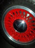
the red paint on the four jaw chuck is from painting BBS wheels for my Ford. I used a modified and adjustable wheel hub to hold the wheels for painting.
Clear as mud? I hope not. I wish I had more pictures.
 

Attachments

  • WELD POSITIONER CHUCK.jpg
    WELD POSITIONER CHUCK.jpg
    64.8 KB · Views: 806
  • BBS ON THE WELD POSITIONER.jpg
    BBS ON THE WELD POSITIONER.jpg
    51.5 KB · Views: 638
  • welding positioner.jpg
    welding positioner.jpg
    44.5 KB · Views: 575
  • welding positioner 4 jaw.jpg
    welding positioner 4 jaw.jpg
    103.3 KB · Views: 637
  • WELD POSITIONER WORKS.jpg
    WELD POSITIONER WORKS.jpg
    61.5 KB · Views: 699
  • weld positioner reverse.jpg
    weld positioner reverse.jpg
    64.9 KB · Views: 681
  • WELD POSITIONER OUT OF SERVICE..jpg
    WELD POSITIONER OUT OF SERVICE..jpg
    100.4 KB · Views: 706
Last edited:
To avoid these ads, REGISTER NOW!

matt_i

Well-known member
Joined
Mar 14, 2008
Messages
10,725
Location
SE Michigan
Great stuff! Lots of chain drives there!

I thought about it once, so I am curious how you handle the grounding current part of it, directly thru the bearing or bronze slip-ring/bronze pressure-roller or ?

I have a couple of light (1500) truck front wheel bearings I was going to use, that's the part gathering dust currently :)
 

Stooge

Well-known member
Joined
Mar 24, 2013
Messages
3,533
Location
South Shore, MA
Very cool! is the angle of the chuck/ holder adjustable? what are you going to be welding that prompted building this?
 
OP
I

isb cornbinder

Well-known member
Joined
Nov 3, 2010
Messages
7,073
Location
Pacific South West, BC, Canada
Great stuff! Lots of chain drives there!

I thought about it once, so I am curious how you handle the grounding current part of it, directly thru the bearing or bronze slip-ring/bronze pressure-roller or ?

I have a couple of light (1500) truck front wheel bearings I was going to use, that's the part gathering dust currently :)

I did mention, but maybe not clearly, I bought and installed a magnetic ground that allows the mounting surface to rotate while maintaining a ground connection. The mag ground is on a flange on the other end of the shaft that carries the table or the chuck. No current goes through bearings.
 
OP
I

isb cornbinder

Well-known member
Joined
Nov 3, 2010
Messages
7,073
Location
Pacific South West, BC, Canada
Very cool! is the angle of the chuck/ holder adjustable? what are you going to be welding that prompted building this?
I am using the screw motor actuator that was used to adjust the angle of the treadmill running surface. A bellcrank, cross shaft, some half sprockets joined by chains and Bob'so your uncle. The chuck moves 90* from vertical to horizontal. The angle can be changed while the chuck is moving or stationery
The build cost about $50 and 20 hours of looking at the pieces. Final assembly was a couple of hours.
Why did I build this welding positioner? I had two flanges to TIG weld to exhaust pipes for a set of headers I was building for my Ford Flathead V8.
I used the positioner rotation to weld a better base for my shop chair. It was handy for welding some short sections of pipe together.
The positioner and wheel hub adapter makes painting wheels easy. I also used the positioner to turn some BBS wheels while I polished the flanges. Slow rotation made masking off the flanges for painting easier.
I did use the welding positioner to slowly turn a 16 inch bar with a swivel and 20 feet of 1/8 cable around while the other end of the cable was fixed to the wall. A toy monkey on a unicycle would roll the length of the cable and back.
I don't have an immediate need for it, so, it just sits on a bench.
The magnetic ground is rated at 100 amps.
 
Last edited:
OP
I

isb cornbinder

Well-known member
Joined
Nov 3, 2010
Messages
7,073
Location
Pacific South West, BC, Canada
I thought my wiring looked like shyte, so thanks for the positive comment.
I will add a picture of the header when I get home this evening.
Because someone is going to ask, I TIG welded short tubes into the flange plates then added the mandrel bent elbows after. I do not have any pictures during the construction. Then, again, I may have. My picture filing is so much better in 2018 a decade ago. I am renaming pictures as I need and find them.
Some of the other exhaust parts were TIG welded also. I built a temporary adjustable bracket to adapt to the pipe and mount in the 4 jaw chuck. I have a support for the long end, somewhere.
I don't see the bracket in my bracket collection, so, I must have recycled it.
 
Last edited:
OP
I

isb cornbinder

Well-known member
Joined
Nov 3, 2010
Messages
7,073
Location
Pacific South West, BC, Canada
The weld positioner was perfect for pin-stripping hubcaps. I TIG welded a dual "O" ring flange into the end of the charge-air duct where it connects to the intake manifold.
the right side headers do not look like they might fit on a positioner. It took some "finagling" and time before I got it to be centered for welding.
The look-a-like distributor cap will get red stripes in the cut grooves.
In answer to, "Can she still hang clothes on it?" At my age that is less likely to happen than it was 40 years ago when we got married. She had proper towel bars installed in her ensuite renovation.[/B]
 

Attachments

  • crank position sensor assembly.jpg
    crank position sensor assembly.jpg
    57.9 KB · Views: 257
  • pinstrip hubcap 2.jpg
    pinstrip hubcap 2.jpg
    66.2 KB · Views: 219
  • CHARGE AIR DUCT TO INTAKE2.jpg
    CHARGE AIR DUCT TO INTAKE2.jpg
    65.8 KB · Views: 223
  • polished ceramic.jpg
    polished ceramic.jpg
    146.3 KB · Views: 262
Last edited:
OP
I

isb cornbinder

Well-known member
Joined
Nov 3, 2010
Messages
7,073
Location
Pacific South West, BC, Canada
A guy from the neighbourhood has been "hounding me" about his buying the weld positioner. His price is right, BUT, I do not want to sell the positioner to someone within walking distance. I will likely need the WP in the near future, so ………………. This makes his $450 offer not such a tempting deal.
There are lots of inexpensive treadmills on CL. Buy one and make your own WP. You can "borrow" all of the information you need and take pictures here.
 
To avoid these ads, REGISTER NOW!

xman_charl

Well-known member
Joined
May 16, 2017
Messages
194
Location
Northern California
been using this for several years

motor is dc, got it from surplus center
adapter plate connects to a gear box


P1020557.jpg


Charl
 
OP
I

isb cornbinder

Well-known member
Joined
Nov 3, 2010
Messages
7,073
Location
Pacific South West, BC, Canada
I think your weld positioner is really well done. You have enough power with that motor.
I do not remember the power of the 90 volt Pacific Scientific DC motor in the WP I built. It is way more power than I will ever need.
If I were to do this again and source the components from another tread mill, I would likely build vertically rather than trying to keep all of the components confined inside one 18 inch (45.72cm) square area. It is very congested in the cabinet. I doubt anyone was more surprised than I, when my WP started and ran in both directions.
Another change I would make is to use a variable frequency drive and build out from that.
The biggest complaint I have of my WP is the weight. I think a conservative guess would be around 100 pounds. (45.4kg)
 

dogdog

Well-known member
Joined
Nov 15, 2011
Messages
12,711
where do you guys find those Chucks....

and what size is good / common ?
 
OP
I

isb cornbinder

Well-known member
Joined
Nov 3, 2010
Messages
7,073
Location
Pacific South West, BC, Canada
I find chuicks and lots of other stuff on Craigslist. I paid well under $100 for the one in the picture I posted. There are two four jaw chucks on CL local for $100 each, asking.
The best chuck is the one that fits your need. Accuracy is not important for a weld positioner. 4 jaw is important.
 

dogdog

Well-known member
Joined
Nov 15, 2011
Messages
12,711
I find chuicks and lots of other stuff on Craigslist. I paid well under $100 for the one in the picture I posted. There are two four jaw chucks on CL local for $100 each, asking.
The best chuck is the one that fits your need. Accuracy is not important for a weld positioner. 4 jaw is important.

:( CL wants $200 for a well used 8" in my area .... and only 1 post... too many dreamers here..

Thanks for the tip, will search for a 4 jaw.
 
OP
I

isb cornbinder

Well-known member
Joined
Nov 3, 2010
Messages
7,073
Location
Pacific South West, BC, Canada
I men't no disrespect: The only worthless post is mine.
I am like so many others in awe of your project shown and shared in all of the photos; Indeed I would love to see the exhaust, And wish my wires were as pretty as yours.
Maybe I did not use the weld positioner so much on this header build. Building the weld rotator was fun and challenging.
The complete exhaust system was sent for ceramic coating.
 

Attachments

  • 8.8 rear in ther, really.jpg
    8.8 rear in ther, really.jpg
    77.4 KB · Views: 151
  • header and collector left.jpg
    header and collector left.jpg
    55 KB · Views: 128
  • HEADERS RIGHT 1.jpg
    HEADERS RIGHT 1.jpg
    50.3 KB · Views: 118
  • HEADERS RIGHT FRONT.jpg
    HEADERS RIGHT FRONT.jpg
    69 KB · Views: 112
  • HEADERS RIGHT.jpg
    HEADERS RIGHT.jpg
    68.4 KB · Views: 108
  • Headers2.jpg
    Headers2.jpg
    21.8 KB · Views: 263
OP
I

isb cornbinder

Well-known member
Joined
Nov 3, 2010
Messages
7,073
Location
Pacific South West, BC, Canada
Nice job on the positioner! I built one back in 2010 from a bunch of scrap. It still cost me another $700 at the time and it doesn't even tilt.
I am thinking I have about $200 into this paperweight. If I were to do this again, I will include what have learned to make this better and easier. One of these "ways" is to operate the tone-wheel on a separate shaft at twice the motor RPM. The teeth generate photo-variations, which activate a sensor and a signal to the treadmill computer. The computer thinks the motor rpm is double and slows the motor. I can drive the chuck as low a one rpm, now. Slower is the challenge.
Another learned thingee is to build vertically and avoid congestion.
 
To avoid these ads, REGISTER NOW!
Top Bottom