To avoid these ads, REGISTER NOW!

Welding table

benray666

Member
Joined
Dec 30, 2016
Messages
5
Location
Farnham, Québec, CAN
Hi, i'm new in the forum since today!!!

First, please excuse my poor english, i'm a french Québécois but i will do my best.

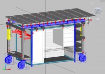
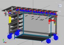
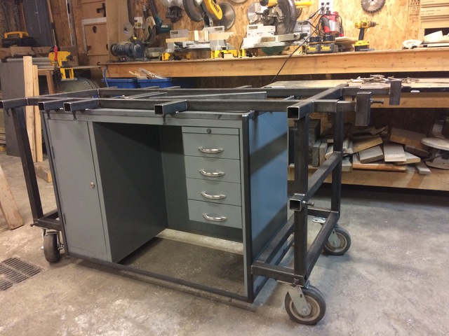
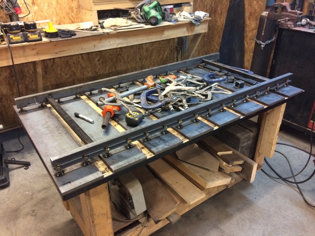
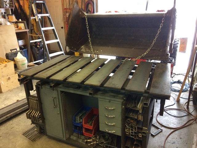
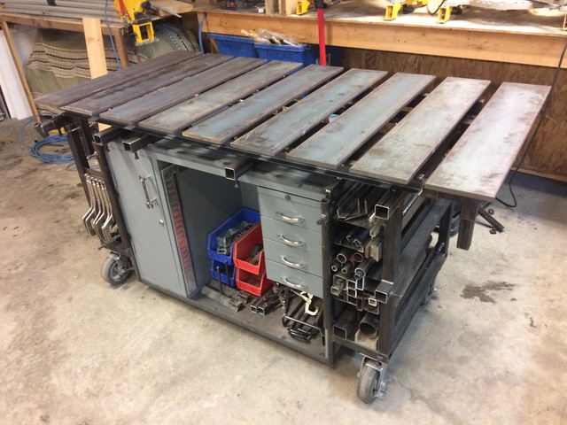
To do a short history, in 2014 i saw a welding table on my wife's Pinterest and i start planing one for me. I read a lot on the internet especially on this forum. I find some tread about table by a member named AMCguy in BC who inspired me a lot and another guy near me in Québec, NASTYZEN.

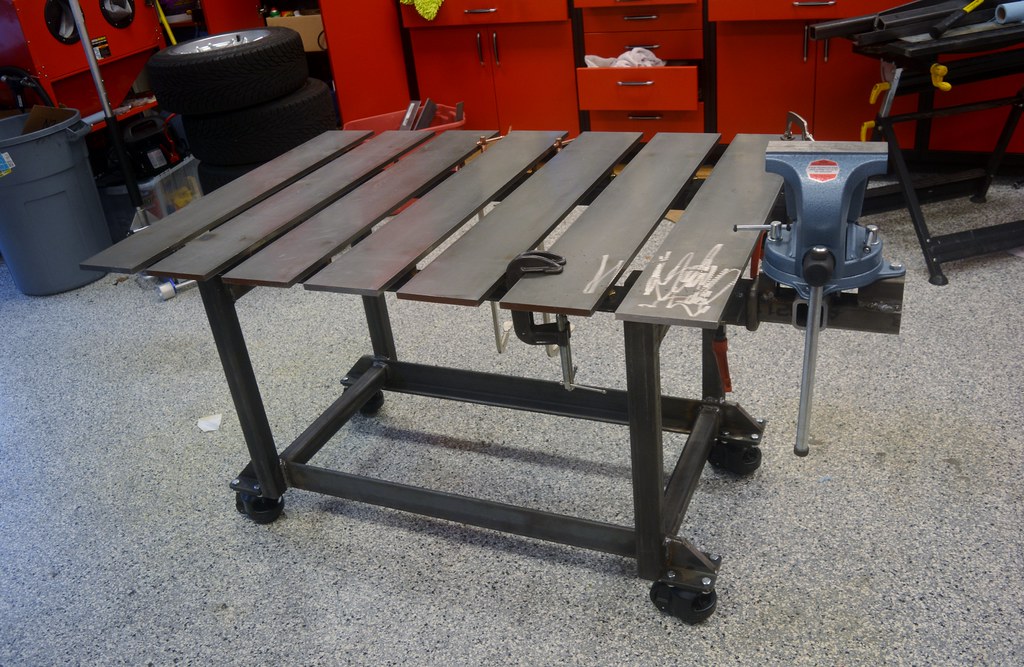
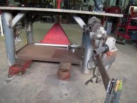
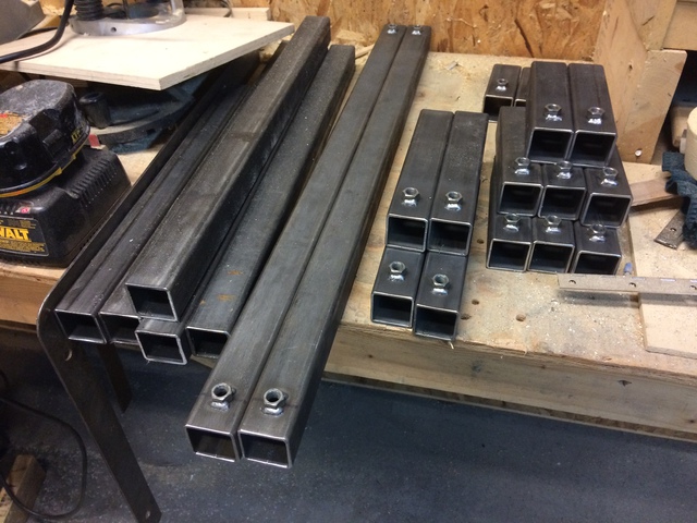
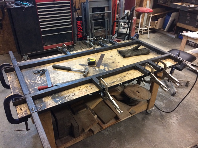
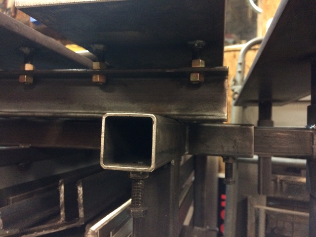
Last month I finally got enough time to begin the project!!!

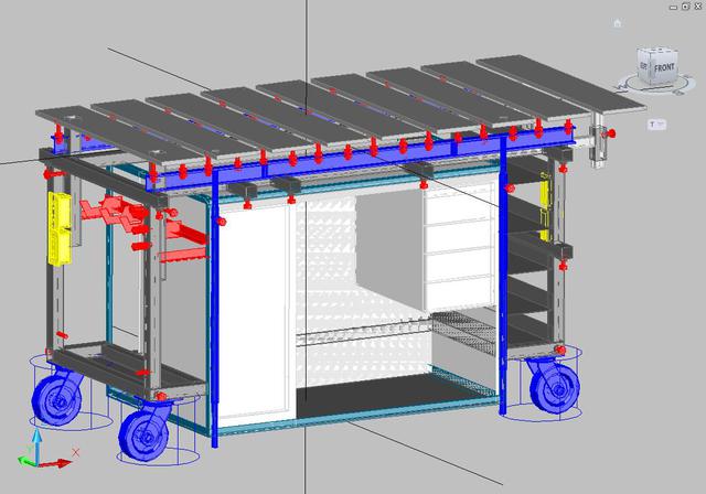
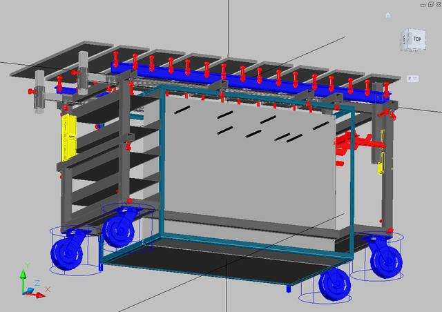
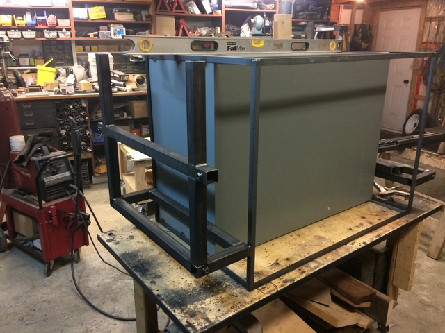
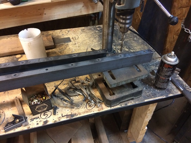
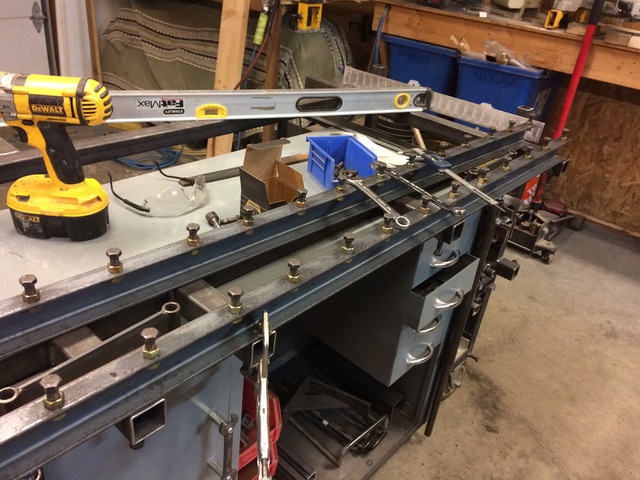
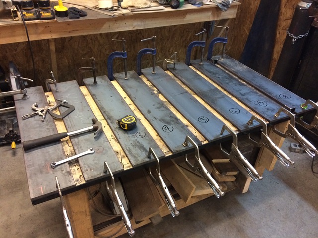
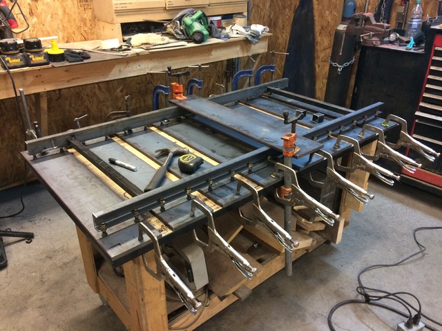
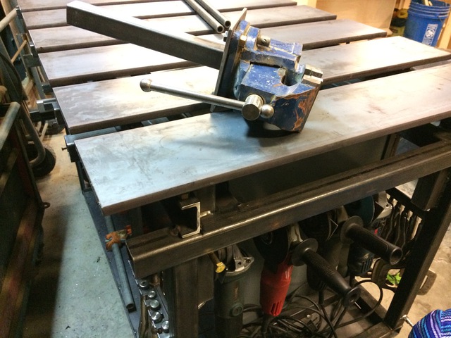
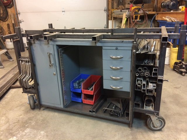
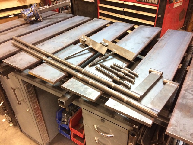
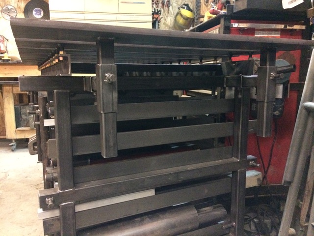
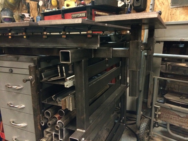
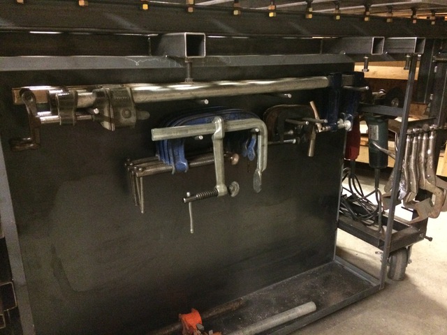
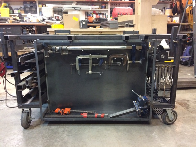
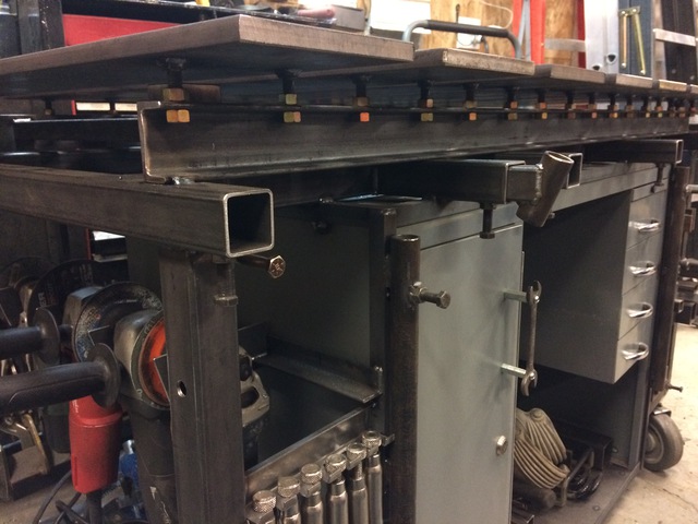
I find a little secretary desk near in Bedford for 60$ and just begin to design around it...
 

Attachments

  • Cad-1.JPG
    Cad-1.JPG
    112.8 KB · Views: 332
  • Cad-2.JPG
    Cad-2.JPG
    99 KB · Views: 282
  • IMG_0772.jpg
    IMG_0772.jpg
    141 KB · Views: 313
  • IMG_0994.jpg
    IMG_0994.jpg
    141.3 KB · Views: 384
  • IMG_0996.jpg
    IMG_0996.jpg
    139.9 KB · Views: 409
  • IMG_1004.jpg
    IMG_1004.jpg
    146.9 KB · Views: 376
  • IMG_1009.jpg
    IMG_1009.jpg
    140.2 KB · Views: 469
To avoid these ads, REGISTER NOW!

bullnerd

Well-known member
Joined
Sep 17, 2012
Messages
5,690
Location
Jersey
Very nice!

Congrats on getting to build your design. I really like it.

You live near NASTYZEN? LUCKY! (in my best Napoleon dynamite voice!)
 

Mgnu

Well-known member
Joined
Jun 5, 2013
Messages
425
Location
Valley of the Sun, AZ
I would love to see two more detailed photos if you are willing:

1. A close up of the bar/attachment method you used for your grinders
2. A close up of the area where you hang the locking c clamp pliers


Looks like a great table!
 

machine_punk

Well-known member
Joined
May 14, 2011
Messages
2,540
Location
Napa Valley, California
Welcome to Garage Journal! Thanks for posting a project with pictures.

It looks like the locking C-Clamps are being held by their adjustment knobs.

That is an interesting plan for the angle grinders. I assume you mounted them sideways because you like to leave the handles attached.

It looks like the last slat can slide out, to support longer project. Nice. I haven't seen that before.

Those are interesting built-in material clamps too. I haven't seen that before either. It looks like they could clamp a VERY large project and reach to the middle of the table.

Nicely done. Clean fabrication and great design features.

Looking forward to pictures of new projects from you.

KDub
 

tig

Well-known member
Joined
Feb 7, 2011
Messages
1,053
Location
Durango, CO
Ok, that's damn cool.

My recently build table has some similarities to yours. I may steal some of your ideas for storage for mine though!

31861772506_f15f76be1d_b.jpg


I built mine with some overhang and am now thinking I don't like that. I was thinking about cutting my planks shorter, but now I may expand the base to include useful storage solutions like you did!
 

Provincial

Well-known member
Joined
Sep 21, 2011
Messages
6,855
Location
Near Salem, OR
Good looking table!

I used a similar system for holding my grinders, but I had room enough to put the handles toward the inside of the table, and I angled them for closer spacing. I also made the mounting on a hinge so I have clear access under the table.
 

Attachments

  • Weld Table 11.jpg
    Weld Table 11.jpg
    36.3 KB · Views: 152
  • Weld Table 14.jpg
    Weld Table 14.jpg
    33.9 KB · Views: 135

stage20

Well-known member
Joined
Nov 5, 2013
Messages
3,722
Location
pcola FL
I like the way the handles for the grinders are turned in on the last post. All the tables look great
Nice way to.build around that desk, gotta have drawers for consumables and small items. Helps keep everything together. Makes for extra work when you are running back to your box for something.
 

PorscheSki89

Member
Joined
Jan 14, 2008
Messages
6
Benray666 what is thickness and width of top plates? Why did you attach with screw adjustments versus welding direct to the C channel supports? How much space between the top plates and why? I'm going to build one very similar to yours. Very nice work!


Sent from my iPad using Tapatalk
 

ovrrdrive

Well-known member
Joined
Sep 13, 2015
Messages
642
Location
Central Florida
Going out on a limb here but the way he attached them makes them adjustable to keep everything level. If they were welded it would be a one shot deal and also if not careful just welding them on could cause them to warp.
 

tig

Well-known member
Joined
Feb 7, 2011
Messages
1,053
Location
Durango, CO
Going out on a limb here but the way he attached them makes them adjustable to keep everything level. If they were welded it would be a one shot deal and also if not careful just welding them on could cause them to warp.

My top plates are 36x6x1/2".

I used bolts/nuts for leveling. I went about 1.5" from plank to cross member.
 
To avoid these ads, REGISTER NOW!
OP
B

benray666

Member
Joined
Dec 30, 2016
Messages
5
Location
Farnham, Québec, CAN
The first design was made in square 2.25'' but with all the top plate, i think it been to heavy and i also lost space between leg and bracket so, the table is made of square steel 1.5'' x 1.5'' x .100''wall and all the accessories will be mount on square steel 1.25'' x 1.25'' x .125''wall. All the square receiver are drilled 7/16'' and weld with a 3/8NF24 nut to tighten the accessories. So i just decided to put a maximum of receiver for almost all apllication possible. Specially for them at the top of the casters, i haven't design an application but for me it seems the right thing to do instead off welding a rectangular bottom at 45 degres corners.

The top was a big issue, i design with channel 2''x6'', with rectangle 2''x6''also try H-beam 4''x4'' but to be sure that all plate will be flat, i think the best way for my application was 9 steel plate CR 1/2''x6''x32''. But when i went to my supplier, they charge me 40$ each plate... A little bit expensive for my application, i decided to go with a hot-rolled plate at 16$each bolt-on a channel to fully adjust the flatness of all plate together.

Hum, not very the best words to describe-it... So let's the pics talks :

Design in AutoCad 2010
17010401332722503214747438.jpg

17010401332922503214747439.jpg


The receivers 1.5''x1.5''x.100''wall nut welded and assembled
17010401333522503214747440.jpg

17010401334822503214747441.jpg


The cabinet frame angle 1''x1''x.125''
17010401343022503214747442.jpg


With old heavy duty 7.375''casters
17010401343422503214747443.jpg


Grinder headquarters with left futur power outlet and right air compressed, bottom in and up 3-way out
17010401363022503214747445.jpg


The trim storage made with 5x 20Ga U-bend metal sheet
17010401364122503214747447.jpg


Drilling the channel 1''x2''
17010401375922503214747451.jpg


The installation of the bolts and nut 1'' high
17010401385422503214747453.jpg


Spacing 1.5'' between the top plate 1/2''x6''x32''
17010401383022503214747452.jpg


Welding bolts and plates
17010401393122503214747454.jpg


Unclamp and flip on the frame with a little bit horsepower...
17010401395322503214747455.jpg

17010401414322503214747458.jpg


Finish product
17010401415722503214747459.jpg


Some close pics on demand :

Vise-grip holder in a square 1.25''x1.25'x.0625''
17010401445122503214747466.jpg


4 grinder holder support by a angle 1''x1''x.125''
17010401450822503214747469.jpg

17010401451722503214747471.jpg

17010401452822503214747472.jpg


Receiver for the vice-stand, will be stretch up through the top plate
17010401453422503214747473.jpg

17010401462722503214747477.jpg


Some of the pipe stand bracket and pin gauge
17010401363722503214747446.jpg

17010401465822503214747479.jpg


Adjustable slide-out support 48'' long
17010401425022503214747461.jpg

17010401422422503214747460.jpg


Clamps holder and futur accessories holder storage
17010401332322503214747437.jpg

17010401370922503214747449.jpg


More pics
17010401444422503214747465.jpg

17010401440722503214747464.jpg
 

skipnay

Well-known member
Joined
Dec 11, 2014
Messages
600
Location
PA
I can't stop looking at this table. I'm having a hard time trying to figure out if I want to do pieces like you did or just drill holes with a mag drill and make one big table. Love the locking plier holders!!! What is the measurement of the top? Length and width? Sorry I might have missed it.
 

d33pt

Well-known member
Joined
Oct 26, 2008
Messages
547
What is the reason for planks with spacing between? I'm not too familiar with welding tables. Looks amazing though. I'd love one. I just weld on the ground usually.
 

skipnay

Well-known member
Joined
Dec 11, 2014
Messages
600
Location
PA
What is the reason for planks with spacing between? I'm not too familiar with welding tables. Looks amazing though. I'd love one. I just weld on the ground usually.

They do that so they can get clamps between them!!! I'm sure there is other reason's also!
 

NASTYZEN

Well-known member
Joined
Jun 11, 2010
Messages
2,823
Location
St-Colomban,Que. Canada
Hey! Belle table mon voisin et bienvenue aux site!

Cool table, I like the clamping feature yours has. I think I might make a pull out section for mine. I sure could of used it the other day.

Farnham to here 3hrs?
 
OP
B

benray666

Member
Joined
Dec 30, 2016
Messages
5
Location
Farnham, Québec, CAN
What is the measurement of the top? Length and width? Sorry I might have missed it.
66''x36'', 9 top plate of 6''x32'' each spacing of 1.5'' between

What is the reason for planks with spacing between? I'm not too familiar with welding tables.
To put clamps between the plates when you're mounting an assembly, like this image
9cbb7be7c4c839ae9e468ec54b2e537b.jpg


all that weight you need a briggs and stratton to move it around
The secret is the heavy duty casters with grease ******.

Farnham to here 3hrs?
With google maps 1h31 by the Pont Champlain without traffic!!! Your welding table is awesome, it's part of my inspiration.
 
To avoid these ads, REGISTER NOW!
Top Bottom