To avoid these ads, REGISTER NOW!

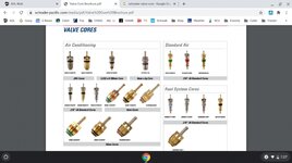
What Depresses Schrader Valve in Compression Tester?

peejay75

Well-known member
Joined
Sep 4, 2017
Messages
312
I always thought a Schrader valve needed a physical object to depress it (like airing up a tire, or sports ball).

But I am learning that the adapter hoses for compression (and probably leak-down) testers have a Schrader valve in them. Am I correct to assume that the compression stroke (air pressure) is what forces the Schrader valve open? And if so, wow!
 
To avoid these ads, REGISTER NOW!

richfinn

Well-known member
Joined
Jan 29, 2011
Messages
4,821
Location
Leeds, Yorkshire, England
It's just there to record/hold max pressure, if anything physically held it open the needle would just flicker.

They used to remove the valve when doing "running compression tests" before in cylinder pressure transducers came along for engine diagnostics.
 
OP
P

peejay75

Well-known member
Joined
Sep 4, 2017
Messages
312
Wow! Thanks, all! (I'm going to be using one of the youtuber's tricks of removing the schrader valve from the adapter hose, and connecting the hose to a vacuum/pressure gauge to find TDC, and I wondered "why remove the schrader valve? do they even have a schrader valve???"). Now I know!

It's just there to record/hold max pressure, if anything physically held it open the needle would just flicker.
Nail...head
 
Last edited:

Blt2Lst

Well-known member
Joined
Jul 9, 2015
Messages
731
Location
SoCali
This issue just came up for me the other day, was trying to do a leak down test on an engine using the hose that came with my compression tester, after a little head scratching finally realized that I needed to remove the schrader valve from the hose in order to use my homemade leak down tester.
I was able to easily remove it with the schrader valve core remover I had for doing AC work.
 
OP
P

peejay75

Well-known member
Joined
Sep 4, 2017
Messages
312
This issue just came up for me the other day, was trying to do a leak down test on an engine using the hose that came with my compression tester, after a little head scratching finally realized that I needed to remove the schrader valve from the hose in order to use my homemade leak down tester.
I was able to easily remove it with the schrader valve core remover I had for doing AC work.
Record-scratch...

You had to remove the schrader valve for a leak down test? Alrighty, inquiring minds wanna know, how does your leak down tester work?
 

2ndGearRubber

Well-known member
Joined
Mar 24, 2014
Messages
14,185
Location
Pittsburgh
Record-scratch...

You had to remove the schrader valve for a leak down test? Alrighty, inquiring minds wanna know, how does your leak down tester work?

You can't put pressure in through the Schrader on a compression tester. Flow only goes from the cylinder into the gauge, can't go the other way.

Thus if using that hose on a leak down tester you would need to remove the Schrader valve. If not you're only doing a leak down test on the hose.
 

rust in the eye

Well-known member
Joined
Oct 2, 2017
Messages
2,875
Location
Chicagoland
(I'm going to be using one of the youtuber's tricks of removing the schrader valve from the adapter hose, and connecting the hose to a vacuum/pressure gauge to find TDC,
I don't think this will be a very reliable way of finding TDC.
If you will be doing anything with the valve train please remind yourself of the consequences for getting it wrong.
 

2ndGearRubber

Well-known member
Joined
Mar 24, 2014
Messages
14,185
Location
Pittsburgh
I don't think this will be a very reliable way of finding TDC.
If you will be doing anything with the valve train please remind yourself of the consequences for getting it wrong.

Depends on what "tdc" is relevant to your goals. I wouldn't time an injection pump off of when a leak down tester builds peak resistance.

But when I do a leak down, I just spin the engine over until it build pressure and push it as hard as I can to get the reading. If it has acceptable leak down numbers, that's good enough. If it has an issue, I'll worry about balancing the crank to hold near TDC to actually find the leakage.
 
OP
P

peejay75

Well-known member
Joined
Sep 4, 2017
Messages
312
(Is posting YouTube links allowed? If so...)

Here's a link to the video of finding TDC using this method, please let me know if there are flaws to this!


My goals: vehicle 1 - find TDC in preparation for crankshaft pulley removal, then timing belt replacement; vehicle 2 - find TDC to do a leak-down test (suspect valve stem seals)
 

rust in the eye

Well-known member
Joined
Oct 2, 2017
Messages
2,875
Location
Chicagoland
He himself calls it "a quick and dirty way". If moving too slowly for the last few degrees leakage might prevent the gauge from moving at all.
An experienced hand can often feel the dead spot at TDC but I still prefer to view the marks.
If doing leakdown precise TDC is crucial, leave a wrench on the crank bolt and you'll know why.
@OP regarding valve stem seals. A leakdown or compression test is worthless for this as the seals outside of the area that sees compression.
 
OP
P

peejay75

Well-known member
Joined
Sep 4, 2017
Messages
312
@OP regarding valve stem seals. A leakdown or compression test is worthless for this as the seals outside of the area that sees compression.
Man, I'm off (today)! I get it, provided the valves/seats are sealing, no air will make it up to the stem seals!

(What if you supplied air on the intake and exhaust strokes? Would that reveal a valve stem seal leak?)
 

APEowner

Well-known member
Joined
Oct 2, 2009
Messages
4,169
Location
Sunny, New Mexico
A schrader valve is really a check valve. If you open it by depressing the end then air can flow both ways and flows easier in the forward direction.

To do a cylinder leakdown test using a compression gauge adapter you need to remove the valve so that air can flow into the cylinder.

I use a compression gauge to determine if a cylinder is on the compression stroke when the crankshaft marks indicate top dead center. That method has nowhere near the sensitivity to find TDC with any level of accuracy.

When I'm using the gauge to determine if it's on the compression stroke I leave the valve in, turn the crank until TDC is indicated and then press the pressure relief valve on the gauge. If it's on the compression stroke there will be an audible puff of air.

The valve stem seals seal between the valves and the guides. There's no practical way to test them with air pressure. Technically you could somehow pressurize the port but there's going to be so much air leaking in other places it'll be impossible to tell if any of it is going past the valve seal. I suppose if you had the valve cover off you could put soapy water on the seal and see if there are any bubbles but if you have access to the seal you can just see if it's still there and pliable.
 
OP
P

peejay75

Well-known member
Joined
Sep 4, 2017
Messages
312
When I'm using the gauge to determine if it's on the compression stroke I leave the valve in, turn the crank until TDC is indicated and then press the pressure relief valve on the gauge. If it's on the compression stroke there will be an audible puff of air.
I like this!

One more question, though, what about finding TDC for cylinders other than #1?
 

Mgdoug3

Well-known member
Joined
Mar 2, 2018
Messages
1,391
Location
KY
I like this!

One more question, though, what about finding TDC for cylinders other than #1?
On a high performance in-line 6 cylinder engine I set the valves at TDC. I start at 0 degrees then move 120 degrees and adjust the next cylinder in the firing order. So it's 0 (cylinder 1), 120 (5), 240 (3), 0 (6), 120 (2), and finally 240 (4).
 

richfinn

Well-known member
Joined
Jan 29, 2011
Messages
4,821
Location
Leeds, Yorkshire, England
In the old days my boss used to attach a football whistle to a tube he had welded up to an old hollowed out spark plug to find TDC, he was pretty good at it too, my job was to push the car in gear until the whistle blew then we would jam the flywheel and introduce air into the cylinder to find the leak.

He had been doing this kind of test since before WW2, way before leak down testers were available!!!!
 
OP
P

peejay75

Well-known member
Joined
Sep 4, 2017
Messages
312
On a high performance in-line 6 cylinder engine I set the valves at TDC. I start at 0 degrees then move 120 degrees and adjust the next cylinder in the firing order. So it's 0 (cylinder 1), 120 (5), 240 (3), 0 (6), 120 (2), and finally 240 (4).
Okay, REALLY last question...

What do you use to know you've rotated the crankshaft 120 degrees? A degree wheel? Marks on the pulley/crankshaft/bolt?
 
To avoid these ads, REGISTER NOW!

Mgdoug3

Well-known member
Joined
Mar 2, 2018
Messages
1,391
Location
KY
Okay, REALLY last question...

What do you use to know you've rotated the crankshaft 120 degrees? A degree wheel? Marks on the pulley/crankshaft/bolt?
I either use a degree wheel when assembling or a marks on a pulley/damper if I have verified it's accurate.
 

Schurkey

Well-known member
Joined
Oct 27, 2011
Messages
2,384
Location
The Seasonally Frozen Wastelands
Worth mentioning: If you use a tire valve stem valve core in your compression tester, expect to get unreasonably-low compression readings from then on. Actual compression-tester valve cores have very soft springs; tire valve stem cores have stiffer springs.

IF one was to perform a leakdown test, use the leakdown tester at low pressure (~20 psi) to find TDC. Set the leakdown tester to some low pressure, as stated. Plug it into the cylinder adapter. The gauge may or may not show pressure depending on whether the valves are closed or open. A long-handle ratchet or breaker-bar is used to "bump" the crankshaft in the normal direction of rotation. Either the gauge doesn't move (valves open) or the gauge shows pressure (valves closed). As the crank is bumped, and the piston comes up the bore, the pressure reading will jump up (more pressure) then reduce. Bump again...needle jumps up, then reduces. Near TDC, the needle doesn't jump up very much. Tells you you're close. At some point, the gauge needle jumps DOWN, because you've gone past TDC and now the piston is going down the bore--telling you you've gone too far.
 

Wrench97

Well-known member
Joined
Jun 23, 2018
Messages
12,361
Location
Southeastern Pa
In the old days my boss used to attach a football whistle to a tube he had welded up to an old hollowed out spark plug to find TDC, he was pretty good at it too, my job was to push the car in gear until the whistle blew then we would jam the flywheel and introduce air into the cylinder to find the leak.

He had been doing this kind of test since before WW2, way before leak down testers were available!!!!
In the 70's we had a adapter that screwed into the plug hole, 1 for Ford and 1 for everything else...and fed shop air in and listened to where it leaked out.
 

joecon

Well-known member
Joined
Oct 4, 2010
Messages
689
It depends on the engine and the location of the spark plugs. But it is usually easy to find TDC. Most people use a screwdriver, but I prefer a brass rod, you put it in the spark plug hole and watch it move up and down. Unless the plug is in at a bad angle this works well. I also have a whistle that fits in the spark plug hole and makes a noise when the piston rises on the compression stroke. The best way is to use a dial indicator in the spark plug hole. That is overkill most of the time. Once you have found TDC on #1 follow the firing order and you can do the leak down test in the least number of crankshaft rotations (2). If you have a scope a running compression wave form tells you more than a leak down could ever tell you. A leak down test was my go-to for years but the scope beats it hands down and is quicker also.
 

joecon

Well-known member
Joined
Oct 4, 2010
Messages
689
Also you can make a simple leak down tester. All you need is an air regulator, set it to 100psi, for auto engines 40psi for small engines, then hook it to the adapter. you can use compression tester adapters with the valve core removed, of the adapters they use to hold the valves closed when you change the valve springs.
 
OP
P

peejay75

Well-known member
Joined
Sep 4, 2017
Messages
312
Thanks for all the EXCELLENT tips everyone, learned several new things today! Hope to employ some/all/combo of these methods soon!
 

2ndGearRubber

Well-known member
Joined
Mar 24, 2014
Messages
14,185
Location
Pittsburgh
Okay, REALLY last question...

What do you use to know you've rotated the crankshaft 120 degrees? A degree wheel? Marks on the pulley/crankshaft/bolt?

Don't piss around with that. Unless you have a lot of room to swing a ratchet, or mark the crank, it's a waste of time.

Just go from one cylinder to another in whatever order and rotate the thing until you feel it hit compression. Have the leak-down tester supplying like 40psi into the cylinder, you'll feel it. Then bump the pressure up, and rotate the engine against it. Doesn't need to be perfect TDC, valves are closed most of the compression stroke. Push against the resistance, look at the gauge. If it looks good, back your regulator down. Don't just let the engine recoil and spin partially backwards as some timing systems don't like that.

it's WAY less effort this way. Either you have a single cylinder to check, in which case who cares just spin the thing until you hit the compression stroke, or you're doing all of them, in which case who cares because all the plugs are out and it takes zero effort to spin the thing.
 

Schurkey

Well-known member
Joined
Oct 27, 2011
Messages
2,384
Location
The Seasonally Frozen Wastelands
(2). If you have a scope a running compression wave form tells you more than a leak down could ever tell you. A leak down test was my go-to for years but the scope beats it hands down and is quicker also.
HOW are you performing this? I have a couple of 'scopes, and some accessories.

The Snap-On Counselor II has a cranking-speed rotational-speed adapter; supposedly useful on 6 poppers and fewer cylinders; doesn't seem to be rated for 8 cylinders. It would be similar to a crank sensor where the waveform shows the speed variation of the crank as each cylinder gets loaded during the compression stroke. I suspect it doesn't provide enough signal differentiation as the cylinder count goes up. I've never used that adapter--never needed to know rotational variation in too-few-cylinder engines.

Similarly, there's a vacuum probe that can be synchronized to #1, that shows instantaneous intake vacuum per cylinder. I hardly ever use that function.

I've seen folks clamp an ampere probe onto the main starter cable, which generates an amperage signal for each cylinder. When synchronized to #1 cylinder compression stroke, you'd have an amperage graph of each cylinder as it goes through the higher load of compression. Low-compression cylinders produce lower amperage draw. But it doesn't tell you WHY the compression is low.

I'd be REALLY interested to discover your method, where the 'scope can tell me if a certain intake valve is leaking, a certain exhaust valve is leaking, the rings are leaking excessively, or there's compression going into the cooling system. I have no idea how a 'scope can diagnose those things, the way a leakdown test can.
 

Schurkey

Well-known member
Joined
Oct 27, 2011
Messages
2,384
Location
The Seasonally Frozen Wastelands
Also you can make a simple leak down tester. All you need is an air regulator, set it to 100psi, for auto engines 40psi for small engines, then hook it to the adapter. you can use compression tester adapters with the valve core removed, of the adapters they use to hold the valves closed when you change the valve springs.
The shop I worked at, did exactly that before I bought a leakdown tester.

Works just fine for diagnosing leaking intake or exhaust valves, or finding if compression is leaking into the cooling system. It works OK for finding holes in pistons. (Because the regulator won't be able to maintain pressure when the leakage is that severe.)

It's totally worthless for diagnosing bad rings. Rings ALWAYS leak compression into the crankcase. By the time the air echos around in there, a small leak can sound like a big one. Without instrumentation, (including a reasonably-sized/shaped orifice that the compressed-air has to blow through before getting to the cylinder) there's no way to determine how much the rings are leaking--acceptable leakage vs. excessive leakage.

So plugging regulated, but not instrumented compressed air into a cylinder is a quick, easy, cheap, but not definitive test.
 
Last edited:

Spareparts

Well-known member
Joined
Mar 12, 2010
Messages
2,051
Location
Lansing Ks.
I havent done a leak down pressure test in years, my tester has 2 gauges on it, always do a compression test first, if you got a low cylinder
then do a leak down test on that cylinder. Doesn't make sense to test a cylinder with good compression, your looking for a problem unless
you are just experimenting or playing. On a suspect cyl. run it up to TDC lock it down and pressurize it up and look at the second gauge
and if their is a 10-15 percent difference listen, the engine will tell you where the problem is. Now with all that said, I have never worked on a
overhead cam engine, don't want to and don't care to learn.
 

xjfish

Well-known member
Joined
Feb 22, 2014
Messages
1,316
Air.

For a "running" compression test, remove said valve.
 

2ndGearRubber

Well-known member
Joined
Mar 24, 2014
Messages
14,185
Location
Pittsburgh
HOW are you performing this? I have a couple of 'scopes, and some accessories.

The Snap-On Counselor II has a cranking-speed rotational-speed adapter; supposedly useful on 6 poppers and fewer cylinders; doesn't seem to be rated for 8 cylinders. It would be similar to a crank sensor where the waveform shows the speed variation of the crank as each cylinder gets loaded during the compression stroke. I suspect it doesn't provide enough signal differentiation as the cylinder count goes up. I've never used that adapter--never needed to know rotational variation in too-few-cylinder engines.

Similarly, there's a vacuum probe that can be synchronized to #1, that shows instantaneous intake vacuum per cylinder. I hardly ever use that function.

I've seen folks clamp an ampere probe onto the main starter cable, which generates an amperage signal for each cylinder. When synchronized to #1 cylinder compression stroke, you'd have an amperage graph of each cylinder as it goes through the higher load of compression. Low-compression cylinders produce lower amperage draw. But it doesn't tell you WHY the compression is low.

I'd be REALLY interested to discover your method, where the 'scope can tell me if a certain intake valve is leaking, a certain exhaust valve is leaking, the rings are leaking excessively, or there's compression going into the cooling system. I have no idea how a 'scope can diagnose those things, the way a leakdown test can.

You need an in cylinder pressure transducer, and a digital storage oscilloscope.

An in cylinder measurement can replace a traditional compression gauge, as well as be used to measure valve timing events in degrees. Very nice versus taking a cam/crank correlation pattern on some engines.

Typically for bottom end problems, you would use a sync to a cylinder, and use a piezoelectric pulse sensor in the dipstick tube or similar. Again for a head gasket issue with compression entering the cooling system, the pulse sensor can be moved to the radiator. Only works for blatantly blown head-gaskets, not stuff that sips coolant. For the top end you need to look at the in-cylinder waveform.

Typically in auto repair - relative compression condemns the engine and the owner junks it.


I havent done a leak down pressure test in years, my tester has 2 gauges on it, always do a compression test first, if you got a low cylinder
then do a leak down test on that cylinder. Doesn't make sense to test a cylinder with good compression, your looking for a problem unless
you are just experimenting or playing. On a suspect cyl. run it up to TDC lock it down and pressurize it up and look at the second gauge
and if their is a 10-15 percent difference listen, the engine will tell you where the problem is. Now with all that said, I have never worked on a
overhead cam engine, don't want to and don't care to learn.

Cam position doesn't matter. Same deal with SOHC or DOHC.
 

Spareparts

Well-known member
Joined
Mar 12, 2010
Messages
2,051
Location
Lansing Ks.
2Gear I just never messed with them, and getting to old to learn. Retired at 75, that was 3 yrs. ago
enjoying the piddling in my shop and waiting on the wife.
 

Schurkey

Well-known member
Joined
Oct 27, 2011
Messages
2,384
Location
The Seasonally Frozen Wastelands
You need an in cylinder pressure transducer, and a digital storage oscilloscope...
Yup, I'm getting a clue now.

Typically in auto repair - relative compression condemns the engine and the owner junks it.
I'm out of the auto-repair industry in large part because of this. Folks with fancy cars refusing repairs 'cause "it costs too much". The thinking is that it's better to spend WAY more money on "new, with a warranty" than take a risk on the vehicle they already own, which they've already depreciated.

I havent done a leak down pressure test in years, my tester has 2 gauges on it,
Most--not all--leakdown testers have two gauges, with the orifice in-between. My first leakdown tester was a Snap-On MT324, single-gauge tester. Orifice is after the regulator, but ahead of the single gauge. I bought this around 1988-ish, I think.
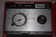
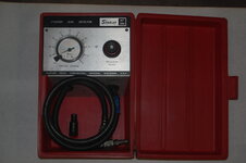
Snap-On_MT324_Leakdown_01.jpg

DSC_0014.JPG

Later I bought an automotive and aircraft-suitable two-gauge unit, in part because it had the standardized, FAA-approved .040 orifice, but also because the Master Orifice for Teledyne-Continental engines seemed like a wise thing--the Master Orifice allows you to "calibrate your expectations" upon each use. I STRONGLY recommend the ATS 2EM.
Most folks will want to tell them to include the 14mm adapter instead of the 18mm it normally ships with. (Or buy a bunch of different adapters...)
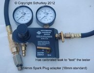
Leakdown_Tester_01.JPG
Although for my purposes--strictly automotive and generally higher-performance applications--the Master Orifice is too generous with the leakage. I accept about 2/3 of what the Master Orifice/Continental shows as acceptable.

always do a compression test first,
Or a cylinder-balance test. Either way, you're looking for one or more cylinders that don't measure-up to the rest.

On a suspect cyl. run it up to TDC lock it down and pressurize it up and look at the second gauge
and if their is a 10-15 percent difference listen, the engine will tell you where the problem is.
The INDICATED leakage has as much to do with the leakdown tester orifice (NOT the "Master Orifice") as the actual leakage. Which is why the Master Orifice is so helpful, especially to folks who aren't used to their leakdown tester.

Listen at the exhaust pipe. You hear noise, it's a leaking exhaust valve.
Listen at the throttle body, with the throttle open somewhat. You hear noise, it's a leaking intake valve.
Look in the radiator or surge tank. You see bubbles/turbulence, you've got a compression leak into the cooling system--head gasket or cracked casting.

LASTLY, listen at the oil-fill cap. You WILL hear noise, and that's the point where you need the gauges. IF the leakdown percentage is acceptable--AND THAT VARIES WITH THE SIZE OF THE ORIFICE, and can be confirmed with the Master Orifice, if the tool is equipped--you're good to go in terms of ring leakage. If the gauges show excessive leakage, you've got piston/ring/cylinder wall problems and either you drop a bore-scope into the cylinder or the heads are coming off for inspection.

Now with all that said, I have never worked on a
overhead cam engine, don't want to and don't care to learn.
Overhead cam engine is compression- or leakdown-tested no differently than a flathead, or a pushrod engine. Nothing different at all.
 
Last edited:

2ndGearRubber

Well-known member
Joined
Mar 24, 2014
Messages
14,185
Location
Pittsburgh
Yup, I'm getting a clue now.


I'm out of the auto-repair industry in large part because of this. Folks with fancy cars refusing repairs 'cause "it costs too much". The thinking is that it's better to spend WAY more money on "new, with a warranty" than take a risk on the vehicle they already own, which they've already depreciated.


Most--not all--leakdown testers have two gauges, with the orifice in-between. My first leakdown tester was a Snap-On MT324, single-gauge tester. Orifice is after the regulator, but ahead of the single gauge. I bought this around 1988-ish, I think.

Snap-On_MT324_Leakdown_01.jpg

DSC_0014.JPG

Later I bought an automotive and aircraft-suitable two-gauge unit, in part because it had the standardized, FAA-approved .040 orifice, but also because the Master Orifice for Teledyne-Continental engines seemed like a wise thing--the Master Orifice allows you to "calibrate your expectations" upon each use. I STRONGLY recommend the ATS 2EM.
Most folks will want to tell them to include the 14mm adapter instead of the 18mm it normally ships with. (Or buy a bunch of different adapters...)

Leakdown_Tester_01.JPG
Although for my purposes--strictly automotive and generally higher-performance applications--the Master Orifice is too generous with the leakage. I accept about 2/3 of what the Master Orifice/Continental shows as acceptable.


Or a cylinder-balance test. Either way, you're looking for one or more cylinders that don't measure-up to the rest.


The INDICATED leakage has as much to do with the leakdown tester orifice (NOT the "Master Orifice") as the actual leakage. Which is why the Master Orifice is so helpful, especially to folks who aren't used to their leakdown tester.

Listen at the exhaust pipe. You hear noise, it's a leaking exhaust valve.
Listen at the throttle body, with the throttle open somewhat. You hear noise, it's a leaking intake valve.
Look in the radiator or surge tank. You see bubbles/turbulence, you've got a compression leak into the cooling system--head gasket or cracked casting.

LASTLY, listen at the oil-fill cap. You WILL hear noise, and that's the point where you need the gauges. IF the leakdown percentage is acceptable--AND THAT VARIES WITH THE SIZE OF THE ORIFICE, and can be confirmed with the Master Orifice, if the tool is equipped--you're good to go in terms of ring leakage. If the gauges show excessive leakage, you've got piston/ring/cylinder wall problems and either you drop a bore-scope into the cylinder or the heads are coming off for inspection.


Overhead cam engine is compression- or leakdown-tested no differently than a flathead, or a pushrod engine. Nothing different at all.

1st job always is to look at the gauge. No sense looking or listening anywhere with sub 10% leak.

Most good running engines, in cars made in the last 30 years, are in the low single digits. If I see a cylinder with 5% that's a lot in my world, but not going to cause issues.
 

richfinn

Well-known member
Joined
Jan 29, 2011
Messages
4,821
Location
Leeds, Yorkshire, England
HOW are you performing this? I have a couple of 'scopes, and some accessories.

The Snap-On Counselor II has a cranking-speed rotational-speed adapter; supposedly useful on 6 poppers and fewer cylinders; doesn't seem to be rated for 8 cylinders. It would be similar to a crank sensor where the waveform shows the speed variation of the crank as each cylinder gets loaded during the compression stroke. I suspect it doesn't provide enough signal differentiation as the cylinder count goes up. I've never used that adapter--never needed to know rotational variation in too-few-cylinder engines.

Similarly, there's a vacuum probe that can be synchronized to #1, that shows instantaneous intake vacuum per cylinder. I hardly ever use that function.

I've seen folks clamp an ampere probe onto the main starter cable, which generates an amperage signal for each cylinder. When synchronized to #1 cylinder compression stroke, you'd have an amperage graph of each cylinder as it goes through the higher load of compression. Low-compression cylinders produce lower amperage draw. But it doesn't tell you WHY the compression is low.

I'd be REALLY interested to discover your method, where the 'scope can tell me if a certain intake valve is leaking, a certain exhaust valve is leaking, the rings are leaking excessively, or there's compression going into the cooling system. I have no idea how a 'scope can diagnose those things, the way a leakdown test can.
Just to add to What Scott said

Search out Brandon Steckler (the following is a free taster of his training course)


Schurkey

Well-known member
Joined
Oct 27, 2011
Messages
2,384
Location
The Seasonally Frozen Wastelands
1st job always is to look at the gauge. No sense looking or listening anywhere with sub 10% leak.

Most good running engines, in cars made in the last 30 years, are in the low single digits. If I see a cylinder with 5% that's a lot in my world, but not going to cause issues.
As said...the INDICATED leakage has as much to do with the tester used, as the actual leakage.

I can get you excellent leakdown numbers from a crappy, worn-out engine. Just let me screw around with the orifice between the gauges.

OR--and this hits kinda close to home--I can get terrible numbers from perfectly-good engines, again by changing the orifice. My Snap-On leakdown tester pictured above did exactly that. It was sensitive beyond all reason--freshly-broken-in engines would show 20%+. Iron Duke engines that drove into the shop, might show 80% leakage. I've since repaired it so it's wonderfully in-line with the ATS leakdown tester.

Again, this can all get compensated-for, if one uses a Master Orifice to calibrate your expectations.

What I'm getting at, is that there is no such thing as saying "10% leakdown is fine"; or "5% leakdown is good" because it all depends on the orifice in the tester being used. In the AUTOMOTIVE world, there is no law, regulation, or "industry standard" for the size and shape of the orifice--a leakdown-tester manufacturer designs whatever-the-hell he wants, and puts it on the market. Which is why I went to an Aircraft-suitable tester. The FAA DOES list specs for the orifice, so that one tester should be comparable to another from a different manufacturer--assuming they're both built to comply with FAA specs.

Why don't I care about looking at the gauges first? Because ANY audible leakage out the valves (intake, or exhaust, or both) is too much, no matter what the gauge says. ANY leakage into the cooling system is too much, no matter what the gauge says. The gauge readings are meaningless to me until I start assessing how much is going past the rings. And when assessing ring leakage, the gauge readings are invaluable--AFTER you know what they "should" be for the leakdown tester being used, 'cause again, not all testers indicate the same amount of leakage on a given cylinder due to differences in construction.
 

2ndGearRubber

Well-known member
Joined
Mar 24, 2014
Messages
14,185
Location
Pittsburgh
As said...the INDICATED leakage has as much to do with the tester used, as the actual leakage.

I can get you excellent leakdown numbers from a crappy, worn-out engine. Just let me screw around with the orifice between the gauges.

OR--and this hits kinda close to home--I can get terrible numbers from perfectly-good engines, again by changing the orifice. My Snap-On leakdown tester pictured above did exactly that. It was sensitive beyond all reason--freshly-broken-in engines would show 20%+. Iron Duke engines that drove into the shop, might show 80% leakage. I've since repaired it so it's wonderfully in-line with the ATS leakdown tester.

Again, this can all get compensated-for, if one uses a Master Orifice to calibrate your expectations.

What I'm getting at, is that there is no such thing as saying "10% leakdown is fine"; or "5% leakdown is good" because it all depends on the orifice in the tester being used. In the AUTOMOTIVE world, there is no law, regulation, or "industry standard" for the size and shape of the orifice--a leakdown-tester manufacturer designs whatever-the-hell he wants, and puts it on the market. Which is why I went to an Aircraft-suitable tester. The FAA DOES list specs for the orifice, so that one tester should be comparable to another from a different manufacturer--assuming they're both built to comply with FAA specs.

Why don't I care about looking at the gauges first? Because ANY audible leakage out the valves (intake, or exhaust, or both) is too much, no matter what the gauge says. ANY leakage into the cooling system is too much, no matter what the gauge says. The gauge readings are meaningless to me until I start assessing how much is going past the rings. And when assessing ring leakage, the gauge readings are invaluable--AFTER you know what they "should" be for the leakdown tester being used, 'cause again, not all testers indicate the same amount of leakage on a given cylinder due to differences in construction.

My issue with "audible" leakage is that between a noisy shop and loss of hearing, it's not always so easy.


As to your point, one needs to trust their equipment. Manufactures give leak down % and delta % between cylinders as guidance. If the proper tool is used, % numbers work fine. However with an improper tool, obviously that won't be the case. That's the nice thing about the scope. Relative compression, long crank, horizontal ruler across the peaks. Dump a transducer in the low hole, check crank case pressure. If it aint going in there, head needs to come off. Or better yet just swap the engine out.

I VERY rarely use a compression gauge, mostly as a teaching tool or to compare to a minimum number on a worn out engine since a pressure transducer doesn't get the "pump up" effect of cranking compression. I still do leak down engines occasionally, but the diag is complete when I say "mechanical fault". Usually that just condemns the vehicle anyways.
 

Wrench97

Well-known member
Joined
Jun 23, 2018
Messages
12,361
Location
Southeastern Pa
My issue with "audible" leakage is that between a noisy shop and loss of hearing, it's not always so easy.


As to your point, one needs to trust their equipment. Manufactures give leak down % and delta % between cylinders as guidance. If the proper tool is used, % numbers work fine. However with an improper tool, obviously that won't be the case. That's the nice thing about the scope. Relative compression, long crank, horizontal ruler across the peaks. Dump a transducer in the low hole, check crank case pressure. If it aint going in there, head needs to come off. Or better yet just swap the engine out.

I VERY rarely use a compression gauge, mostly as a teaching tool or to compare to a minimum number on a worn out engine since a pressure transducer doesn't get the "pump up" effect of cranking compression. I still do leak down engines occasionally, but the diag is complete when I say "mechanical fault". Usually that just condemns the vehicle anyways.
Absolutely correct rarely do they get repaired, they get junked, sold to someone that has a good engine from a wreck and can do the work him/herself or go to the Hyundai/Kia dealer for warranty.......
 

joecon

Well-known member
Joined
Oct 4, 2010
Messages
689
I like that aircraft tester it looks like a nice unit and the price is reasonable. I like the single gauge units because they can flow more air, and that makes it easier for me to hear the leak.
There are a lot of videos on YouTube about using the scope to diagnosis engine faults. There are several tests you can do. In cylinder pressure is one, it gives you a lot of information and can be done cranking or running. You can put a pressure transducer on the intake and use it like a Vacuum gauge. You can use the same transducer in the exhaust, and on the dip stick tube to check the bottom end.
 
To avoid these ads, REGISTER NOW!
Top Bottom