To avoid these ads, REGISTER NOW!

What drum switch for my setup?

bareass172

Well-known member
Joined
Aug 5, 2012
Messages
817
Location
N'awlins
I apologize as I'm sure this is a common question, I read several posts similar to mine just under here as I'm posting. I have very literally been searching the internet for about 6 months (off and on) trying to find my solution with no luck. My particular motor appears, to me at least, to be slightly different from the majority of reversing drum switch setups. I walked into Grainger to ask for help there and they pushed me out the door with a generic switch that I don't think is what I need for my motor. I brought my motor diagram in, they wouldn't even look at it.

I want to wire the motor for 220V, reversing.

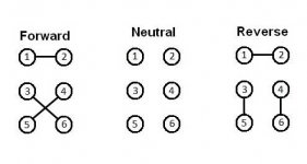
I attached a picture of my motor plate, I attached a diagram that covers like 99% of the drum switches I found scouring the net (the same Grainger pushed on me), and the last picture (with the "X" connection) is the only type of switch I can see that would work for my motor but I can't find a switch that works like that.

I'm not electrically stupid, but I think I've been looking for this information for so long that I'm having a "forest from the trees" moment. Not that it matters, but this is for my lathe. I also know that I could accomplish this with a separate switch from the reversing drum switch (2 switches, basically) but would really prefer to just have the single drum switch.

Can this be done with a 6 pole switch or do I need 8 poles? :dunno:

I'm feeling kinda stupid - so thanks in advance for the help!
 

Attachments

  • motor.jpg
    motor.jpg
    112.7 KB · Views: 25
  • Dayton-Switch.jpg
    Dayton-Switch.jpg
    12.9 KB · Views: 16
  • Dayton-Switch-2.jpg
    Dayton-Switch-2.jpg
    13.1 KB · Views: 15
To avoid these ads, REGISTER NOW!

Bert_

Well-known member
Joined
Dec 24, 2016
Messages
9,693
Location
NW Iowa
The first drum switch is what you need.
0189a231-180d-48ea-a1ec-bfc3ec308fcf.jpg


Normally you would also need to connect T8 to the drum switch but since it is connected to the center of the run winding when wired for 230V, simply hooking up T5 like I showed should work, It will swap it from one line to the other when put it FW/REV

Also if the forward position on the switch does not make the motor spin the direction you want, you can move T5 from terminal 3 to terminal 4 on the drum switch.

And you probably know this already. Single phase motors will not reverse instantly, you have to allow it to stop turning before you can put it in reverse. otherwise it will just keep going the same direction.
 
Last edited:
OP
B

bareass172

Well-known member
Joined
Aug 5, 2012
Messages
817
Location
N'awlins
Bert,
First, thanks so much for the reply. Second, I don't understand how that configuration works? The L1 to T1 I get and the L2 to T4 makes sense, but I'm supposed to have to swap the T5 and T8 between an isolated bundle and/or the L2. I completely understand that you may know something I don't, but I'd greatly appreciate an explanation so I can understand why. My understanding and knowledge of wiring the motor combined with that motor plate tells me that I should wire it like the image I attached. That would do what the motor plate shows.

Thanks for any explanation!
 

Attachments

  • Dayton-Switch-2.jpg
    Dayton-Switch-2.jpg
    32.3 KB · Views: 8
To avoid these ads, REGISTER NOW!

Bert_

Well-known member
Joined
Dec 24, 2016
Messages
9,693
Location
NW Iowa
I guess the second drum switch would work also, I didn't think of that as I haven't used that type before for a single phase motor. The only downside is that it only interrupts one line but I don't consider that a major issue.

I'm glad you put that up since I hadn't thought of it.
I'll explain my version anyhow,

I'm probably not going to explain this very well but here goes. First off 5 and 8 are the start winding, the start switch and capacitor (If equipped) are also connected to these leads.

In a dual voltage motor the run windings are connected in series for high voltage operation. The group of leads that the label tells you to "TAPE" is the center of those two windings, that point is roughly 120V to either of the incoming lines.

In your motor the start winding is a 120V winding, so when the motor is wired for high voltage (240V) one end if the start winding is tied to the center point I mentioned above.

All we need to do to reverse the motors rotation, is to reverse the current flow though the start winding relative to current in the run winding. If you follow the instructions on the nameplate you would reverse 5 and 8. A standard drum switch does not have the correct contacts to do that will the motor pictured.

But if we get a bit creative you will notice that swapping T5 from one line to the other will also reverse the direction of current flow through the start winding. So even though it's not what the diagram says it will also reverse the motor, and the best part is it cam be done with a standard drum switch.
 
Last edited:

matt_i

Well-known member
Joined
Mar 14, 2008
Messages
10,722
Location
SE Michigan
Here is the only way I can see to do this. Since the L1/L2 circuit isn't completed no current will flow. However you have to be careful when servicing this as there is always going to be 120vac potential from L1-Gnd. I would recommend a 2-pole disconnect, a warning label, or a twistlock. Before you BBQ me over this check out the Grainger recommended wiring diagram for a 2X440, the 3phase wiring diagram also has one of the hot leads always connected to its winding and not opened by the drum switch....

 
Last edited:
OP
B

bareass172

Well-known member
Joined
Aug 5, 2012
Messages
817
Location
N'awlins
@Bert
Thanks for taking the time to explain that - I have a better understanding of the motor now. I figured it was what you described - a connection that I wasn't aware of, or a different way to look at the same wiring.

@Matt_i
Your suggestion was another consideration I had! I was wondering if it would be safe to connect the L1-T1 direct and account for the L2 disconnect to stop the flow of power. I fully realize what you're saying about there always being electrical potential there, but even with the switch breaking contacts I'd still have electrical potential at the switch unless I shut down the breaker - something I would ALWAYS do anyway. I would never open the motor or the switch without shutting it all down.

I can say that the "X" drum switch I diagrammed above does not exist (that I can find) even though I have seen others reference the same concept on other forums when I was searching for a solution. Is there a preferred method between these 2 suggestions that would be better for any reason?

Thanks again for the help and suggestions!
 
To avoid these ads, REGISTER NOW!
Top Bottom