To avoid these ads, REGISTER NOW!

Whole house fan, 2 fans 1 timer. Backfeed issue

David Paul

Well-known member
Joined
Jul 11, 2014
Messages
684
Location
Western New Jersey
I’m installing a whole house fan and gable vent fan. I’d like both fans to turn on/off with the same Intermatic 12 hour timer. The WHF is a QuiteCool 2 speed that requires a constant 120v, with a spdt switch that supplies 120v to the low/high speed input. The gable fan is also a QuiteCool plug in fan. They are both powered from the same dedicated breaker. Both hot leads for the fans are currently tied together at the timer switch output(120v). From there the WHF lead goes to the speed switch and the gable fan lead direct to the fan. Currently with the timer off, when I plug in the gable fan the WHF turns on without the timer being on. I’m assuming the gable fan is backfeeding the WHF.
What is the solution to this? Can I use a relay to isolate the gable fan from the WHF on the same circuit? Thanks
 
To avoid these ads, REGISTER NOW!

wyliesdiesels

Well-known member
Joined
Aug 14, 2012
Messages
20,073
Location
Modesto, CA
If the timer is off, how is the gable fan getting power? You connecting power behind the timer? If so, well of course the WHF will get power since you have them tied together at the timer.

Im not understanding the issue here. You want both fans to run with the timer. So theyre running as you have hem hooked up.
 

BillK

Well-known member
Joined
Aug 24, 2006
Messages
9,365
Location
Beautiful Southern Maryland
Sounds to me like you might have the neutral and hot reversed on the gable fan ? How about a quick diagram of how you have it wired ?? I am thinking it should be like this :
 

Attachments

  • IMG_20220905_133056432.jpg
    IMG_20220905_133056432.jpg
    179.5 KB · Views: 75

dogdog

Well-known member
Joined
Nov 15, 2011
Messages
12,711
could be hot and neutral is reversed at the whole house fan that was receiving constant power 120V ??? Don't even know why with this arrangement ...

"
I’m installing a whole house fan and gable vent fan. I’d like both fans to turn on/off with the same Intermatic 12 hour timer. The WHF is a QuiteCool 2 speed that requires a constant 120v, with a spdt switch that supplies 120v to the low/high speed input. "

yes pic or some crude schematic would have help.
 

alfredeneuman

Well-known member
Joined
Mar 3, 2011
Messages
4,594
Location
Fullerton, CA

sparky 1971

Well-known member
Joined
Oct 9, 2018
Messages
8,009
Location
Central Iowa
I'm as confused as anyone else here. If the 120 volt goes to the timer first, there should be nothing available to the house fan or the gable fan unless the timer is on. Are you sure the timer is wired properly?

The wire you're calling constant power is the neutral, the hot goes from the timer to the two speed switch and also to the gable fan. Then the switched legs will go from the speed controller to the house fan. The neutral will be tied together at all of the boxes without being attached to anything. It doesn't show that in the picture, it looks like it goes straight through, without going through the control boxes. You could do it that way by setting junction boxes, but it's easier to just take the cable through and wire nut the whites together at each box.
 

sparky 1971

Well-known member
Joined
Oct 9, 2018
Messages
8,009
Location
Central Iowa
Yea, I should have attached this:8B1F794F-642A-4058-BBED-09CF7B846D08.jpeg
That may be the worst diagram I've ever seen. It makes absolutely no sense whatsoever. Look at the diagram in post #5. It will be just like that with an additional 14/2 going from the output side of the timer to the gable fan as well as the input for the two speed switch.
 
OP
D

David Paul

Well-known member
Joined
Jul 11, 2014
Messages
684
Location
Western New Jersey
DA5B2A54-418D-4B73-A9F8-60D300E51831.jpeg

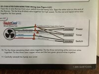
This is how it’s wired. Note constant power to fan.

485EA540-C659-4690-9882-DB1AA99E2F11.jpeg

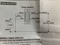
This is how the timer is wired…..Thank You BillK.

With the timer off, when I plug in the gable fan the WHF turns on.
 
OP
D

David Paul

Well-known member
Joined
Jul 11, 2014
Messages
684
Location
Western New Jersey
I would agree, but in that case what is done with the black wire coming from the fan motor itself?
That may be the worst diagram I've ever seen. It makes absolutely no sense whatsoever. Look at the diagram in post #5. It will be just like that with an additional 14/2 going from the output side of the timer to the gable fan as well as the input for the two speed switch.
 

nadogail

Well-known member
Joined
Jan 23, 2009
Messages
32,049
Location
Coronado, CA
After reading this thread, my opinion is your electrician needs to take this project "back to the drawing board".
 
OP
D

David Paul

Well-known member
Joined
Jul 11, 2014
Messages
684
Location
Western New Jersey
To be alittle clearer if I can. From the fan motor itself comes 5 wires. Blue/red/white/black/green. Green and white we know ground/neutral. Blue high speed attached to speed switch. Red low speed attached to switch. Black is currently attached to constant hot.
 

BillK

Well-known member
Joined
Aug 24, 2006
Messages
9,365
Location
Beautiful Southern Maryland
Black is currently attached to constant hot.
When you say "constant hot" do you mean all of the time or when the timer is on ??? If it was all of the time the fan should always run whether the timer is on or not. Do you have a picture of the back of your timer and the 2 speed switch ?
 
OP
D

David Paul

Well-known member
Joined
Jul 11, 2014
Messages
684
Location
Western New Jersey
When you say "constant hot" do you mean all of the time or when the timer is on ??? If it was all of the time the fan should always run whether the timer is on or not. Do you have a picture of the back of your timer and the 2 speed switch ?
Yes, constant even with timer off. Fan does not turn on until power supplied from timer to speed switch. I’ll try and get pictures of switches
 

dogdog

Well-known member
Joined
Nov 15, 2011
Messages
12,711
I think that diagram is confusing as fak , op you should call the company and verify and confirm.

The diagram is a simplified diagram and your QC-xxxx model requires a constant 120V to feed on the black wire... that is why it is wired that way...

lets just walk through this... I think this is how it is working... and why you see the timer black wire and the incoming power is tied together. If it wasn't a USA company, I would have thought this is written and translated from the Chinese LMFAO... f-up to the max confusion... The only other time I seen a wiring diagram similar is those dam German track diagrams... or people that embrace those in the vw world...

Logically this is how this is working, it's the same as the diagram on figure step 6-11 with the exception that you have a constant 120V hot wire feed to that unit for what ever reason.

some basic facts first... you have a timer and a special 3 way switch (spdt center off) with center off I assume that came with the kit. ?

if you take the incoming power it feeds the unit requires constant 120V hot and neutral + ground... pretty clear on that part.

Then it requires you to tap that power and feed the timer... that is why you see the black wire from the timer feeding ... this is confusing if no one explained. the black wire on the timer is the input power... Neutral and ground is as is.

The red wire on the timer is output... which is not in the drawing probably just at the control switch area. It feeds the center tap of the three way switch center off (spdt center off)

from that switch it has two output... dependents on the switch position... so it if high it feeds to the blue wire, if low it powers to the red... It since house hold Romex only have black and white wire... it asked you to tape the white wire black... means only one of those wire is powered at a time.

Now take that guy that wrote the manual to the firing squad.
 
Last edited:

dogdog

Well-known member
Joined
Nov 15, 2011
Messages
12,711
now to figure out how to wire in your "other" fan.

how do you want this to work?

you can tap at constant black wire and that other fan will always have power, you can provide your own control to it..

if you wanted it to work with the timer... you will probably have to run another set of wire from the controls... and see if you can tap the red wire output of the timer (that wire is not shown in your posted diagram). Just make sure the timer have enough amp to support both fans (loads).
 
Last edited:
OP
D

David Paul

Well-known member
Joined
Jul 11, 2014
Messages
684
Location
Western New Jersey
dogdog, your explanation is spot on and the way I understand it. The WHF works just as expected. Timer on, fan on, speed as selected from switch. All good.

I am trying to control a gable fan to also turn on with the timer switch so both fans run at the same time. I have added 14/2 romex to an outlet. Hot to timer red output, white to neutral. All neutrals tied together. When I plug the gable fan into the outlet, the WHF turns on. Timer is off.
 
To avoid these ads, REGISTER NOW!

dogdog

Well-known member
Joined
Nov 15, 2011
Messages
12,711
I have added 14/2 romex to an outlet. Hot to timer red output, white to neutral. All neutrals tied together. When I plug the gable fan into the outlet, the WHF turns on. Timer is off

Without the gable fan plugin. Test the output of that red wire on the timer switch? is it outputting a 120V constantly or only when timer is on? and also make sure you verify you hot and neutral is properly connected that was mentioned. verify that only two wire and a ground is connected to the gable fan right? Black (hot) and white (neutral) and ground.
 
OP
D

David Paul

Well-known member
Joined
Jul 11, 2014
Messages
684
Location
Western New Jersey
Verified outlet wired properly. Timer only out putting 117v while turned on. If I turn on WHF/timer, outlet has 117 and gable fan works when plugged in.
 

Sumboodie

Well-known member
Joined
Mar 20, 2021
Messages
10,755
Location
AK
That may be the worst diagram I've ever seen. It makes absolutely no sense whatsoever. Look at the diagram in post #5. It will be just like that with an additional 14/2 going from the output side of the timer to the gable fan as well as the input for the two speed switch.
The way I interpret that diagram is the power, timer and switch are 3 ways to use the fan and you pick one of those. BUT maybe I'm wrong. Seems like a ton of wiring for a simple fan!
 

dogdog

Well-known member
Joined
Nov 15, 2011
Messages
12,711
Verified outlet wired properly. Timer only out putting 117v while turned on. If I turn on WHF/timer, outlet has 117 and gable fan works when plugged in.
if you verified that the wiring is correct and it is now not acting up... then there is only one more thing to check, is that your timer switch can handle the load of both fans at high speed. Normally those electric timer uses a "relay" to switch and have a limited AMP it can handle, long term wise, if the switch are overloaded it might have short live. you might have to call the company, or trying to figure it out if the spec is there. Good thing both fans are from the same company.
 

BillK

Well-known member
Joined
Aug 24, 2006
Messages
9,365
Location
Beautiful Southern Maryland
I hate to say it but that is the most confusing set of instructions I have ever seen. I have worked with electronics and electrical almost all of my life and I simply cannot figure out what they are trying to get you to do. I would really suggest you call the manufacturer and talk to them before something gets smoked or somebody gets hurt.
 
OP
D

David Paul

Well-known member
Joined
Jul 11, 2014
Messages
684
Location
Western New Jersey
I should have said if I plug in the fan after turning on the timer, it, the gable fan, works properly. The WHF still turns on with the timer off and the gable fan plugged in.
 
OP
D

David Paul

Well-known member
Joined
Jul 11, 2014
Messages
684
Location
Western New Jersey
First, thanks to all that took the time to respond to this thread. The videos the company provides seem to support the wiring diagram including the constant hot directly to the motor.

Good suggestion to call company. I will tomorrow.
 

BillK

Well-known member
Joined
Aug 24, 2006
Messages
9,365
Location
Beautiful Southern Maryland
One more comment and I am done :) I suppose it is possible that this is some type of crazy setup that does require the power all of the time to the fan and in that case it simply might not be possible to do what you are trying to do ?? If you leave the gable fan unplugged does the whole house fan work properly ?
 
OP
D

David Paul

Well-known member
Joined
Jul 11, 2014
Messages
684
Location
Western New Jersey
One more comment and I am done :) I suppose it is possible that this is some type of crazy setup that does require the power all of the time to the fan and in that case it simply might not be possible to do what you are trying to do ?? If you leave the gable fan unplugged does the whole house fan work properly ?
Yes
 

infinkc

Well-known member
Joined
Jan 19, 2012
Messages
862
What it seems is that the whf has constant power ran to it already, and used the low and high lines from the timer to trigger the fan on. Whf probably has some type of relay in it. I could see how the gable fan would trigger the whf in this setup.

Think your only option if you are trying to use the same timer is to wire in a relay off the timer to the gable fan.
 
OP
D

David Paul

Well-known member
Joined
Jul 11, 2014
Messages
684
Location
Western New Jersey
Any luck with this ??
Well it is wired correctly with the constant hot lead according to manufacture. Proper operation as dogdog explained better then I could.

Curious about the 2 neutrals fitter30 refers to.

I am measuring about 2 volts at the timer switch output when the timer is off.

Again thanks to all who took the time to reply.
 

Zeke

Well-known member
Joined
Aug 13, 2009
Messages
17,176
Location
Long Beach CA, the sewer by the sea.
Looking forward to seeing how this is resolved. I don't see the same layout between the hand drawing and the schematic. They look different to me. Looks like the GF is powered by a control wire from the WHF.
 
To avoid these ads, REGISTER NOW!
Top Bottom