To avoid these ads, REGISTER NOW!

Why fuse a neutral?

Snapped-off

Well-known member
Joined
Feb 22, 2012
Messages
4,830
Location
Indiana
Is there any reason to fuse a neutral? Any reason at all? I know it shouldn't be done and why.

Just trying to wrap my head around a situation at work. We have what appears to be a fused neutral inside a disconnect box (it has a fused hot too). The neutral fuse blew, the hot didn't. The disconnect feeds a transformer that feeds 2 120v outlet receptacles.
 
To avoid these ads, REGISTER NOW!

loganb

ALLIANCE MEMBER
Joined
Dec 29, 2011
Messages
5,674
Location
Omaha, NE
Is the equipment of European design and manufacture? It's common over there as most of their electrical systems aren't polarized so they fuse both legs to ensure protection
 
OP
S

Snapped-off

Well-known member
Joined
Feb 22, 2012
Messages
4,830
Location
Indiana
Is the equipment of European design and manufacture? It's common over there as most of their electrical systems aren't polarized so they fuse both legs to ensure protection
I'll have to check, it's a possibility. Do they use any 120 though? I thought they all used 230.
 

loganb

ALLIANCE MEMBER
Joined
Dec 29, 2011
Messages
5,674
Location
Omaha, NE
I'll have to check, it's a possibility. Do they use any 120 though? I thought they all used 230.

Generally they're using 220v, but assuming single phase feed it's the same hookup as our 120v.

Guessing you're doing this because 120v buss bar or service isn't easily accessible where you need it? Been there done that...
 
OP
S

Snapped-off

Well-known member
Joined
Feb 22, 2012
Messages
4,830
Location
Indiana
Generally they're using 220v, but assuming single phase feed it's the same hookup as our 120v.

Guessing you're doing this because 120v buss bar or service isn't easily accessible where you need it? Been there done that...
No idea why it's done the way it is. There's 120 everywhere. One of the 2 outlet receptacles is an isolated ground receptacle, but it's just grounded to the gang box like normal.
 

wyliesdiesels

Well-known member
Joined
Aug 14, 2012
Messages
20,130
Location
Modesto, CA
Is there any reason to fuse a neutral? Any reason at all? I know it shouldn't be done and why.

Just trying to wrap my head around a situation at work. We have what appears to be a fused neutral inside a disconnect box (it has a fused hot too). The neutral fuse blew, the hot didn't. The disconnect feeds a transformer that feeds 2 120v outlet receptacles.
thats a code violation. you can only overcurrent protect a neutral if the ungrounded conductor gets disconnected at the same time.
 

wyliesdiesels

Well-known member
Joined
Aug 14, 2012
Messages
20,130
Location
Modesto, CA
No idea why it's done the way it is. There's 120 everywhere. One of the 2 outlet receptacles is an isolated ground receptacle, but it's just grounded to the gang box like normal.
:shocking: :eek: thats not kosher either. an isolated ground receptacle needs an insulated EGC that runs back to the isolated ground bar.

sounds like you had some hacks working at your facility.

Does the equipment that uses this receptacle require an isolated ground receptacle?
 
OP
S

Snapped-off

Well-known member
Joined
Feb 22, 2012
Messages
4,830
Location
Indiana
:shocking: :eek: thats not kosher either. an isolated ground receptacle needs an insulated EGC that runs back to the isolated ground bar.

sounds like you had some hacks working at your facility.

Does the equipment that uses this receptacle require an isolated ground receptacle?
The further we dug into this the stranger it got.. :lol:

I can't fathom why it's set up the way it is. From the main service panel, a single pole 120 breaker > 240 rated disconnect switch > 70-600 transformer > the 2 gang box. The normal receptacle is unused. The isolated ground is powering 2 ethernet switches for the PLCs of the 2 machines.

First look I thought it was 240 going in, getting stepped down to 120 with the transformer. But looking inside the transformer, there is a pigtail wire running over to the neutral on the normal outlet receptacle.

The neutral for the isolated ground receptacle is running to the ground in the transformer.
 

wyliesdiesels

Well-known member
Joined
Aug 14, 2012
Messages
20,130
Location
Modesto, CA
The further we dug into this the stranger it got.. :lol:

I can't fathom why it's set up the way it is. From the main service panel, a single pole 120 breaker > 240 rated disconnect switch > 70-600 transformer > the 2 gang box. The normal receptacle is unused. The isolated ground is powering 2 ethernet switches for the PLCs of the 2 machines.

First look I thought it was 240 going in, getting stepped down to 120 with the transformer. But looking inside the transformer, there is a pigtail wire running over to the neutral on the normal outlet receptacle.

The neutral for the isolated ground receptacle is running to the ground in the transformer.
Umm what? :shocking:

Have pics?
 

dogdog

Well-known member
Joined
Nov 15, 2011
Messages
12,711
I say talk to your EE guy at the facility why this setup is implemented ? is this an isolation transformer or one of those impedance matching transformers for those weird 3 phase voltages... ? I think if you go google up on that, you'll find a explanation some where that fits your setup. I think that guy Dave from EEVblog also explains it in his famous oscilloscope videos. or you can consult mike halt's forum, I think they have a section on these things.


MBfreak

MEMBER EMERITUS
Joined
Dec 10, 2010
Messages
2,301
Location
Linkoping , Sweden
Copy from above
Is the equipment of European design and manufacture? It's common over there as most of their electrical systems aren't polarized so they fuse both legs to ensure protection.
This DOES NOT apply to the standard 3 phase 400 V system in Europe. At All.
First of all. N is never fused except in ancient UK systems.
A brief description:
Residential or smaller commercial
Here it how it works.
The incoming 3 phase 400 V system is metered, fused and terminated in a distribution central, owned by the utility.
From there 3 phase groups ( L1, L2, L3 and PEN) groups are metered, fused and lined up for several outgoers.
3 Phase 5 wire groups( L1, L2,L3,N, PE) are then run to each billed customer. Usually the incomer in owners fuse board is run thru an OC/Earth fault ( 30 mA) breaker that covers the entire consumers area. Law nowadays.
Larger consumers such as washers, driers , stoves are run 2 phase or 3 phase at 400 V. ( L1, L2, (L3) N and PE
Outlets, lamps etc run Lx, N, PE 230 V
QUITE seldom and only for smaller consumers are fed over single phase 3 wire L1, N, PE over 3 wire at 240 V

Larger commercial LV installations ( ie < 1000 VAC or 1500 V DC) , often 690 V are often run the same way.
Some installations that are prone to smaller earthfaults are often D connected and equipped with earth fault indications with alarm for low EFs and trips for OC and larger EFs

Ola
 

TRWham

Well-known member
Joined
Aug 11, 2017
Messages
1,987
Location
East Cobb County, Georgia
Whenever I encounter something odd in a building we are working on, I apply the rule: "the fact you do not understand why something was done, doesn't make it wrong." I think you will find this was done to provide isolation for the equipment. Maybe a look at the documentation for the equipment or a call to the manufacturer would shed some light on the situation.
 
OP
S

Snapped-off

Well-known member
Joined
Feb 22, 2012
Messages
4,830
Location
Indiana
Umm what? :shocking:

Have pics?
I'll get some today.
I say talk to your EE guy at the facility why this setup is implemented ?
EE guy? Come on :lol: that's why I'm posting here.
Whenever I encounter something odd in a building we are working on, I apply the rule: "the fact you do not understand why something was done, doesn't make it wrong." I think you will find this was done to provide isolation for the equipment. Maybe a look at the documentation for the equipment or a call to the manufacturer would shed some light on the situation.
Our machine prints didn't show anything of value outside of the main control cabinet. Couldn't find any building side prints.

Contacting the manufacturer is a possibility though.
 

dogdog

Well-known member
Joined
Nov 15, 2011
Messages
12,711
EE guy? Come on :lol: that's why I'm posting he
Lol I thought you are looking for an electrician here. Some one must have instructed or ordered that setup dependents on the equipment it is powering.

But seriously, that looks like an isolation transformer setup with isolated ground? Not sure who else other than hospitals have those setups.
 

SlappyWhite

Well-known member
Joined
Oct 3, 2012
Messages
1,819
Location
Upper Canada
It is dangerous, why?....if the neutral fuse/breaker trips the circuit or device is still hot but now not working. Opens up the possibility of getting a shock... Not much different than switching the neutral. Of course it requires everything to have the correct polarization if the fuse is internal to the device.

If it trips you want hot to stop flowing.
 
OP
S

Snapped-off

Well-known member
Joined
Feb 22, 2012
Messages
4,830
Location
Indiana
It is dangerous, why?....if the neutral fuse/breaker trips the circuit or device is still hot but now not working. Opens up the possibility of getting a shock... Not much different than switching the neutral. Of course it requires everything to have the correct polarization if the fuse is internal to the device.

If it trips you want hot to stop flowing.
That's exactly what happened. I'm just confused why the neutral is fused at all.
 
OP
S

Snapped-off

Well-known member
Joined
Feb 22, 2012
Messages
4,830
Location
Indiana
Lol I thought you are looking for an electrician here. Some one must have instructed or ordered that setup dependents on the equipment it is powering.

But seriously, that looks like an isolation transformer setup with isolated ground? Not sure who else other than hospitals have those setups.
I'll post some pics later. I don't have the signal to upload pics right now.

Are you saying the transformer could be in place solely for the isolated ground receptacle? I mean... that's physically what it's there for. That's all it's attached to. I've never dealt with isolated grounds before.
 

dogdog

Well-known member
Joined
Nov 15, 2011
Messages
12,711
I'll post some pics later. I don't have the signal to upload pics right now.

Are you saying the transformer could be in place solely for the isolated ground receptacle? I mean... that's physically what it's there for. That's all it's attached to. I've never dealt with isolated grounds before.

That youtube video explains isolation transformer pretty well..not sure your situation. It's to isolate the electrical with 1:1 transformer... There is a reason they bonded one of the legs to ground as neutral, don't remember. I believe that Dave guy from EEVblog have explained it before. Don't have the toys to play, so don't pay attention. Isolate ground might be a different thing at the plug. Your Electrical Engineer guy should know this or who ever approve that hookup.
 
To avoid these ads, REGISTER NOW!
OP
S

Snapped-off

Well-known member
Joined
Feb 22, 2012
Messages
4,830
Location
Indiana
That youtube video explains isolation transformer pretty well..not sure your situation. It's to isolate the electrical with 1:1 transformer... There is a reason they bonded one of the legs to ground as neutral, don't remember. I believe that Dave guy from EEVblog have explained it before. Don't have the toys to play, so don't pay attention. Isolate ground might be a different thing at the plug. Your Electrical Engineer guy should know this or who ever approve that hookup.
There is no EE guy here. This was installed by a company from Kentucky when the building opened. I don't know if they did the electrical work or if it was subbed out.

I'll check out the video later when I can.
 
OP
S

Snapped-off

Well-known member
Joined
Feb 22, 2012
Messages
4,830
Location
Indiana
setup.jpg
disconnect.jpg
disconnect 2.jpg
transformer 1.jpg
transformer 2.jpg
transformer in.jpgtransformer out.jpg

120 in, 120 out. For the transformer, H1 is 120 in, H2 is neutral in. They both have taps in them for the normal outlet receptacle. X1 is 120 out, X2 is neutral out bonded with ground. They run to the isolated ground receptacle. Everything is ultimately grounded together though. Doesn't that defeat the purpose of a dedicated ground for that receptacle?
 
OP
S

Snapped-off

Well-known member
Joined
Feb 22, 2012
Messages
4,830
Location
Indiana
So I didn't even see it until I just posted the pic, the transformer is a mini computer regulator. So I'm assuming it just provides a nice clean power source to those 2 outlets.
 

dogdog

Well-known member
Joined
Nov 15, 2011
Messages
12,711
So I didn't even see it until I just posted the pic, the transformer is a mini computer regulator. So I'm assuming it just provides a nice clean power source to those 2 outlets.
if you google that thing... it's a line conditioner... I would consider those equipment fuses no ? Not your typical panel fuses, so NEC doesn't dictate it?. If I have to guess, it's probably that setup is generally design for 120 or 240 input... and who ever selected it for 120v input, they don't need to change their design for the fused disconnect..

But yes that device is there to provide stable output to something, not an isolation transformer per-se . orange plugs are always isolated ground. "Supposedly".

 
Last edited:
OP
S

Snapped-off

Well-known member
Joined
Feb 22, 2012
Messages
4,830
Location
Indiana
They're 20A slow blows. We're supposed to be getting some more in today. Still no idea why it blew. Haven't found any shorts anywhere, but there's 250' or so of conduit on the ceiling we can't access. Our tallest lift is about 5' short.

I just don't get why they used this disconnect box.
 

nadogail

Well-known member
Joined
Jan 23, 2009
Messages
32,109
Location
Coronado, CA
When I taught Electrical Wiring I impressed on my students that neutral conductors are “Almost Never” switched or fused.
Service Station Gas Pumps are the most common exception.
 

dogdog

Well-known member
Joined
Nov 15, 2011
Messages
12,711
When I taught Electrical Wiring I impressed on my students that neutral conductors are “Almost Never” switched or fused.
Service Station Gas Pumps are the most common exception.
why is that ? compressors are switched both. drill press also afaik, in the OP's pics , those fuses are consider equipment fuses. ? no ?
 
OP
S

Snapped-off

Well-known member
Joined
Feb 22, 2012
Messages
4,830
Location
Indiana
Well... replaced the fuse and everything is fine. No idea why it popped. Probably never know.

I think the installers just used a 240v disconnect because that's what was on-hand or maybe what the prints called for. Possibly in other locations, this is normally setup with 240 and stepped down to 120 for the outlet box. But they just ran 120 through the disconnect. Seems wrong since whatever happened caused only the neutral fuse to blow. I guess that's all.

The only other thing I'm not really following is the isolated ground receptacle. Everything is ultimately grounded together. Both outlets are tied together and grounded to the box. The box is grounded to the disconnect box which grounds back to the service panel. Doesn't it need its own dedicated ground back to the service panel?
 

dogdog

Well-known member
Joined
Nov 15, 2011
Messages
12,711
Dunno how to answer you... maybe some pro here will step up from the lurking shadows to answer your question/concerns.


walrus

Well-known member
Joined
Nov 12, 2008
Messages
11,686
Location
Maine
When I taught Electrical Wiring I impressed on my students that neutral conductors are “Almost Never” switched or fused.
Service Station Gas Pumps are the most common exception.
Gas pump neutrals are switched but not fused
 

Norcal

Well-known member
Joined
Mar 16, 2008
Messages
13,772
Gas pump neutrals are switched but not fused
As long as a neutral (grounded conductor) is switched simultaneously with ungrounded (hot) conductors it is code compliant to switch them, it is never permitted to switch a grounding conductor, tossing that in although nobody has mentioned it.
 

justsam

Well-known member
Joined
Aug 20, 2010
Messages
1,270
Location
Penngrove, California
Are you sure that is a neutral? Just because it is a white wire does not always make it so. Now that all is operational, what is the voltage across those two fuses?
 
OP
S

Snapped-off

Well-known member
Joined
Feb 22, 2012
Messages
4,830
Location
Indiana
Are you sure that is a neutral? Just because it is a white wire does not always make it so. Now that all is operational, what is the voltage across those two fuses?
Yes. That white wire leads to one of the neutrals on the outlet.

I initially thought it was another 120 because it's fused inside of a 240v box. But after all the digging around it was found to be a neutral.

The sole purpose for all this is to power an outlet that has 2 ethernet switches plugged in.
 

tool_scrounge

Well-known member
Joined
Jul 20, 2010
Messages
4,212
Location
Southern California
Those Sola units work great on filtering power line noise. I have used them in the past and can they make a huge difference in noise on instrumentation.
 
  • Like
Reactions: RPH
OP
S

Snapped-off

Well-known member
Joined
Feb 22, 2012
Messages
4,830
Location
Indiana
Those Sola units work great on filtering power line noise. I have used them in the past and can they make a huge difference in noise on instrumentation.
It almost seems a little unnecessary in the application it's being used for. But I'm no electrical engineer so who knows.
 

nadogail

Well-known member
Joined
Jan 23, 2009
Messages
32,109
Location
Coronado, CA
It appears that my statement that Neutrals are "Almost Never" has been misconstrued, I did not say "Never" but "Almost Never" should cover the applications the majority of Electricians will encounter.
 

RPH

Well-known member
Joined
Dec 17, 2006
Messages
4,190
Location
Michigan Thumb
Sola transformer are common place in industrial controls and medical equipment. Chrysler for the longest time required Sola transformers in every cabinet that had a control. They had noise issues and Sola helped with that. Medical use is for the same reason.
An isolated output is not referenced to ground and that makes it safer. You need to cross both conductors on the output to get a shock.
In fact a lot of the machines I installed the high frequency output is isolated from ground. The entire system is floating. I took some arguments to get engineer to order isolation transformers without a zero tap on it. Canada rules all secondary zero taps must be grounded.
They had equipment that would not run that way. It blew up transistors continuously. After working through it we found the secondary grounded, machine builder is saying that has to go and Canadian code says attached. It took 3 new transformers on the incoming line without the zero tap. 96AC085B-A52B-47B4-8759-A66AD7C2D920.gif
Remove the ground on the secondary and the output means nothing as a shock hazard unless both conductors are touched.
7E407C59-7502-4918-ABE8-FF6C704AD2A6.jpeg
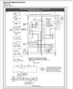
This Square D motor control shows two transformers that noted by manufacturers not to ground them.
Also Sola Transformers are used to supply laptops for programming. They are not meant to run drill motors or grinders. I’m amazed at the breadth and experiences across the board that have not seen floating systems more often.
 
OP
S

Snapped-off

Well-known member
Joined
Feb 22, 2012
Messages
4,830
Location
Indiana
From transistors to transformers, I'll get up to speed eventually!

Am I right in thinking this 240v disconnect is being used for the wrong application since it's only got 120 going through it. We never did figure why the neutral fuse blew.
 

dogdog

Well-known member
Joined
Nov 15, 2011
Messages
12,711
I’m amazed at the breadth and experiences across the board that have not seen floating systems more often
These things are reserve for people with deep pockets and needs in industrial /commercial setups. Not exactly a cheap thing or needs for most people.
 
To avoid these ads, REGISTER NOW!
Top Bottom