To avoid these ads, REGISTER NOW!

Wire help

bluedog225

Well-known member
Joined
Jan 31, 2012
Messages
3,305
Location
Texas
I’d appreciate a consult. I think I’ve done my homework.

I’m going to run wire from my two Schneider XW Pro inverters, to a Schneider power distribution panel and then to my main service panel in my shipping container. About 10 foot run. Then about 125 feet to a subpanel in my workshop. The wire will be underground in a 2” conduit.

The inverters’ output split phase. Each inverter is rated for the following:
  • Continuous output: 6,800 W
  • 30-minute overload: 8,500 W
  • 60-second surge: 12,000 W

I think I size for continuous output. A 60 amp breaker per inverter is specified by the manufacturer.

I was planning to use THHN2 – aluminum and pull individual strands for the line 1, line 2, neutral, and ground. (1/0, 1/0, 1/0, and 8 awg and black, red, white, green).

Conduit fill seems fine and the voltage drop is low (1.5% at full 60 amps).

Is that the right move or should I be looking at something like a mobile home feeder or service entrance cable?

I’ll be buying wire soon. Plan is to measure actual length needed with string and add 15% to length. Leaving additional 6’ extra at each end.

It would be great not to screw this up. A big step towards air conditioning.

Any thoughts appreciated.

Thanks
 
Last edited:
To avoid these ads, REGISTER NOW!

wyliesdiesels

Well-known member
Joined
Aug 14, 2012
Messages
20,071
Location
Modesto, CA
Im a little confused on the wiring and routes. can you post a diagram?

The wire for the inverters will be 10' long? you dont need 1/0 for that. way overkill

75a wire (60a 1.25) would be #4 THWN cu or #3 al

for the 125' run to a subpanel, what size breaker are you feeding it with?
 
OP
B

bluedog225

Well-known member
Joined
Jan 31, 2012
Messages
3,305
Location
Texas
Im a little confused on the wiring and routes. can you post a diagram?

The wire for the inverters will be 10' long? you dont need 1/0 for that. way overkill

75a wire (60a 1.25) would be #4 THWN cu or #3 al

for the 125' run to a subpanel, what size breaker are you feeding it with?

Agreed on the 10’ run. I should have been more clear.

I haven’t purchased the breaker yet for the 125’ run. I was planning a 60 amp 2 pole breaker with a backfeed hold down. It’s going into a “spare” 200 amp Siemens main panel.

I went large with the 1/0 because I dislike the voltage sag when starting the microwave or whatever.

I can draw up a diagram this evening.

Thanks for the response.
 

dcg9381

Well-known member
Joined
Jun 20, 2018
Messages
11,887
Location
Austin, TX
I’m going to run wire from my two Schneider XW Pro inverters, to a Schneider power distribution panel and then to my main service panel in my shipping container. About 10 foot run. Then about 125 feet to a subpanel in my workshop. The wire will be underground in a 2” conduit.
The inverters’ output split phase. Each inverter is rated for the following:
  • Continuous output: 6,800 W
  • 30-minute overload: 8,500 W
  • 60-second surge: 12,000 W
I was planning to use THHN2 – aluminum and pull individual strands for the line 1, line 2, neutral, and ground. (1/0, 1/0, 1/0, and 8 awg and black, red, white, green).
FYI, those inverters are limited to #2 AWG on the output side. I assume you're talking about wire from the distribution panel to main service panel wiring....

60A breakers likely have a wire size limit too, maybe limited to #2 AWG.

A diagram would help.
 
OP
B

bluedog225

Well-known member
Joined
Jan 31, 2012
Messages
3,305
Location
Texas
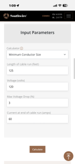
you selected the wrong voltage. should be 240v not 120v

It only gave me the single phase option. I wasn’t sure what voltage to use when thinking about an individual conductor. Since L1 to neutral is 120V.

Entering 240V gives me this. But I’m not real comfortable I’m going about this correctly.
IMG_0176.png
 
OP
B

bluedog225

Well-known member
Joined
Jan 31, 2012
Messages
3,305
Location
Texas
Diagram per request. This should be fun.

Disclaimer- I don’t trust AI with squat. But it is handy at some things.

I’ve reviewed the schematic and it looks right as far as the system layout. While the recommended wire size is problematic.

Better than my scribbles.

Any thoughts appreciated. And I’d like to understand the voltage drop calculator better.

Thanks


IMG_0179.jpeg
 

dcg9381

Well-known member
Joined
Jun 20, 2018
Messages
11,887
Location
Austin, TX
I'm not familiar with the PDP panel. Some can comment on "two feeds" - that's my concern. IT has 2 "2 pole" breakers, a neutral wire that goes nowhere... I think that's like an AI bungle.

You have an upstream current limit (inverters to PDP) of 60A, but downstream you breaker it at 100A. That "main panel" makes no sense, it has a 200A main as well as a 100A back-feed. This says it's an "off grid" system, are the inverters setup to supplement and grid tie?

For feeder to sub panel, you're at 60A peak over 125 feet 240V. Totally agree @wyliesdiesels take on it:
75a wire (60a 1.25) would be #4 THWN cu or #3 al

You're gonna need more help and it's not just on wire size. I haven't done these inverters before, but it looks like the parallel inverter setup (both on 240V) may require some special equipment:

1777327276480.png
 
To avoid these ads, REGISTER NOW!
OP
B

bluedog225

Well-known member
Joined
Jan 31, 2012
Messages
3,305
Location
Texas
Thanks. It’s off grid. No grid tie. The main and sub panels are what I have on hand.
 

dcg9381

Well-known member
Joined
Jun 20, 2018
Messages
11,887
Location
Austin, TX
Thanks. It’s off grid. No grid tie. The main and sub panels are what I have on hand.
Lets start with a diagram (not one built by AI). System design diagram should be the first step. You'll get great support here, but gonna end up in a hard place if you don't understand how to wire these. 100% you can do this, but how this wired comes down to those particular inverters.
If you have the right distribution panel for these, you're probably set - but I doubt that it's wired like that diagram and "lightly" reading the Schnider manuals, it involves jumpers on breakers. There's a bonding issue too that's going to cause GFI drama if you don't get it right.
 
OP
B

bluedog225

Well-known member
Joined
Jan 31, 2012
Messages
3,305
Location
Texas
Lets start with a diagram (not one built by AI). System design diagram should be the first step. You'll get great support here, but gonna end up in a hard place if you don't understand how to wire these. 100% you can do this, but how this wired comes down to those particular inverters.
If you have the right distribution panel for these, you're probably set - but I doubt that it's wired like that diagram and "lightly" reading the Schnider manuals, it involves jumpers on breakers. There's a bonding issue too that's going to cause GFI drama if you don't get it right.


Thanks.

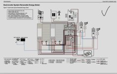
Here is the Schneider diagram detailing the wiring between the two inverters and the power distribution panel. I’m trying to find a better resolution version. I think this is the detail requested.

From this Schneider panel, L1, L2, N, and ground simply go to a main panel, and then a subpanel.

The neutral ground bond will be in the main panel.

There is no external power source.


IMG_5017.jpeg
 
OP
B

bluedog225

Well-known member
Joined
Jan 31, 2012
Messages
3,305
Location
Texas
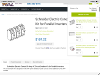
I’ve also got additional similar diagrams for the individual inverters, and the breaker kit for multiple inverters.

Much of this will not be utilized right now. No grid. No generator. There is a transfer switch in place when it’s time to wire in a generator.

I’m happy to provide any additional info. And appreciate the advice.

IMG_5032.jpeg
IMG_5031.png
IMG_5030.png
 

wyliesdiesels

Well-known member
Joined
Aug 14, 2012
Messages
20,071
Location
Modesto, CA
For feeder to sub panel, you're at 60A peak over 125 feet 240V. Totally agree @wyliesdiesels take on it:

I was actually sizing the wire for the inverters. I hadnt sized the feeder because i didnt know what ampacity he was gonna run to it.

but now that we know that, #4 should work
 

wyliesdiesels

Well-known member
Joined
Aug 14, 2012
Messages
20,071
Location
Modesto, CA
@bluedog225 theres a bit to consider when sizing everything for inverters because of bus ratings, etc. you may have to downsize a breaker so you dont go over bus ratings in panels etc

this is why its good to start with a solid plan and system diagram and then work out from there like @dcg9381 has stated...
 
OP
B

bluedog225

Well-known member
Joined
Jan 31, 2012
Messages
3,305
Location
Texas
@bluedog225 theres a bit to consider when sizing everything for inverters because of bus ratings, etc. you may have to downsize a breaker so you dont go over bus ratings in panels etc

this is why its good to start with a solid plan and system diagram and then work out from there like @dcg9381 has stated...

I feel like I’m not understanding.

The inverters are being wired to the Schneider power distribution panel exactly as shown in post 14. The Schneider panel and connection kit for the second inverter are all pre wired. That part was pretty straight forward.

I’m happy to try again at a system diagram but not sure what that means. It would just show conductors to the main panel, then to the subpanel.

And I hear the wire size recommendations. And thanks. But I would like to learn what I’m doing wrong.

And is aluminum thhn-2 the right wire choice?

Thanks all. Sorry if I’m being dense.
 
To avoid these ads, REGISTER NOW!
Top Bottom