To avoid these ads, REGISTER NOW!

Wiring 120v accessory outlets from a junction box on a Bridgeport

jlevers

Well-known member
Joined
Jul 10, 2018
Messages
180
Location
On the road
I'm rebuilding an old Bridgeport, and trying to figure out how to create an outlet for 120V accessories (DRO and work lamp) to plug into. The mill is running on a VFD, which is converting single-phase 220V to 3-phase 220V.

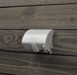
There's already this junction box wired on the side of the mill, with nothing connected to it at the moment. (I know, it's filthy...I'm working on it.)

IMG_8424.jpeg

Warning: I am a very, very amateur electrician, so what I say below might be wildly wrong. That's why I'm coming here before I try anything.

I'm assuming that this junction box was at one point used for what I want to use it for – accessory outlets – but when I measure the voltage between the 3 legs, I get ~200V. Based on the fact that I'm not getting ~120V per leg, I think that this is an extension of the 3-phase system, with no ground.

Is there some way to turn this into multiple 120V outlets? I've done some searching, but everything I've found is for converting 220V single-phase into 120V single-phase outlets, and in all those situations each leg has 120V, which seems to make everything a lot simpler.

Thanks!
 
To avoid these ads, REGISTER NOW!

wyliesdiesels

Well-known member
Joined
Aug 14, 2012
Messages
20,014
Location
Modesto, CA
The VFD is not outputting single phase with a neutral. And even if it did you would not want to power 120v equipment via the VFD because of the variable frequency and voltage output.

You will need to abandoned the feed from the VFD and run a separate circuit for the 120v convenience receptacle…
 

tool_scrounge

Well-known member
Joined
Jul 20, 2010
Messages
4,191
Location
Southern California
How much 120V power do you need? Last time I needed to do something like this I routed the 220V single phase to a step down transformer that converted it to 120V single phase. I also added a fuse on the 220V transformer input side to protect the transformer from overload. Transformers are rated in VA (max volts X amps It can provide). But please talk to someone in person who knows this stuff for your own protection.
 
OP
J

jlevers

Well-known member
Joined
Jul 10, 2018
Messages
180
Location
On the road
The VFD is not outputting single phase with a neutral. And even if it did you would not want to power 120v equipment via the VFD because of the variable frequency and voltage output.

You will need to abandoned the feed from the VFD and run a separate circuit for the 120v convenience receptacle…
That makes sense, thanks. Does it sound reasonable to split the 220 upstream of the VFD, and use the side that's not going to the VFD to power the convenience box? Just trying to avoid needing to plug the mill into both a 220V and 120V outlet.
How much 120V power do you need? Last time I needed to do something like this I routed the 220V single phase to a step down transformer that converted it to 120V single phase. I also added a fuse on the 220V transformer input side to protect the transformer from overload. Transformers are rated in VA (max volts X amps It can provide). But please talk to someone in person who knows this stuff for your own protection.
Not much, although I don't know the actual numbers. Whatever the total amperage of the DRO and the incandescent work lamp is, which I would imagine is pretty small. I'll definitely get some more opinions before doing anything, though. Don't want to fry myself.
 

Cruzan80

Well-known member
Joined
Jul 22, 2015
Messages
4,215
Location
Denver, CO
Wouldn't you just be able to run 4-wire to the box, then have the VFD running off both hots, and a hot/neutral combo for the 120V stuff? Or is there an issue sharing the ground in this situation?
 
  • Like
Reactions: RPH

wyliesdiesels

Well-known member
Joined
Aug 14, 2012
Messages
20,014
Location
Modesto, CA
Does it sound reasonable to split the 220 upstream of the VFD, and use the side that's not going to the VFD to power the convenience box?
Both ungrounded legs are used for the VFD.

As to whether you can use one of the ungrounded conductors for a 120v circuit all depends on the size of the circuit feeding the VFD. Also you will need to pull a neutral.

What kind and size of wire do you have feeding the VFD currently?

Me personally i would just run a separate circuit. It will be cleaner
 

walta

Well-known member
Joined
Jan 13, 2017
Messages
2,311
Location
Dutzow Missouri
I would be surprised if the DRO would not run on any voltage from 90-250

For home use 240 Volt lighting is not technically allowed but seems safe to me.

https://www.amazon.com/Gooseneck-Ma...ndustrial/dp/B088H89397/?tag=atomicindus08-20

For one of my machines, I installed a small stepdown transformer just big enough to run the work light. For another I installed a 4-wire cord and plug and fused the outlet at the machine.

What you don’t want to do is keep the 3-wire cord and use the ground wire as a neutral as any fault in the ground wire would dangerously energize every part of machine.


Walta
 

OccupantRJ

Well-known member
Joined
May 15, 2009
Messages
11,077
Location
Eastern North Carolina
First off, if the VFD is not wired directly to the motor without going through any other switches, this is not how to wire it. It should be 240 volt power to VFD straight to mill motor. Powering the motor on or off and speed controls are done via the low voltage control terminals on the VFD. The original drum switch on the machine CAN be used to control the on-off control terminals of the VFD. I did mine like that, and also added a speed control onto the original switch housing. I would strip all other wiring and original controls off the machine and mount a 120 receptacle to the machine and use a 3 wire power cord to plug it in to an outlet near the machine. This gives you an outlet for a light and also for a 120 volt power feed if using one.
 
OP
J

jlevers

Well-known member
Joined
Jul 10, 2018
Messages
180
Location
On the road
Both ungrounded legs are used for the VFD.

As to whether you can use one of the ungrounded conductors for a 120v circuit all depends on the size of the circuit feeding the VFD. Also you will need to pull a neutral.

What kind and size of wire do you have feeding the VFD currently?

Me personally i would just run a separate circuit. It will be cleaner

Ok, I'll probably just use follow your suggestion and make a separate circuit. There's no super convenient 120V outlet near the mill, but I could make one.

The VFD is running on 14ga stranded wire, on a circuit with a 20A tandem breaker.

I would be surprised if the DRO would not run on any voltage from 90-250

For home use 240 Volt lighting is not technically allowed but seems safe to me.

https://www.amazon.com/Gooseneck-Ma...ndustrial/dp/B088H89397/?tag=atomicindus08-20

For one of my machines, I installed a small stepdown transformer just big enough to run the work light. For another I installed a 4-wire cord and plug and fused the outlet at the machine.

What you don’t want to do is keep the 3-wire cord and use the ground wire as a neutral as any fault in the ground wire would dangerously energize every part of machine.


Walta

The DRO I have says its supposed to run on 220/240, but you might be right that it would work fine on lower voltages. (I don't know if this makes a difference, but this isn't technically in a "home" – it's in an old warehouse – relevant thread here if you're interested).

First off, if the VFD is not wired directly to the motor without going through any other switches, this is not how to wire it. It should be 240 volt power to VFD straight to mill motor. Powering the motor on or off and speed controls are done via the low voltage control terminals on the VFD. The original drum switch on the machine CAN be used to control the on-off control terminals of the VFD. I did mine like that, and also added a speed control onto the original switch housing. I would strip all other wiring and original controls off the machine and mount a 120 receptacle to the machine and use a 3 wire power cord to plug it in to an outlet near the machine. This gives you an outlet for a light and also for a 120 volt power feed if using one.

I rewired the switch so that there's a set of wires going from the VFD to the big breaker box on the back of the mill, which then goes out into the motor, and a set of wires going from the switch to the VFD, as you described. Are you recommending that I get rid of the breaker box entirely and run straight from the VFD into the motor without going through that box? It seems to work fine as is, but if it's unnecessary I can certainly get rid of it. Here's what that box looks like:

IMG_8429.jpeg

This gives you a basic sense of the rewired switch...Excuse the helmet, it was a Halloween joke

IMG_7685.jpeg

Sounds like your suggestion for the 120V accessories is the same as @wyliesdiesels, so that's probably what I'll do – run a separate circuit.
 

OccupantRJ

Well-known member
Joined
May 15, 2009
Messages
11,077
Location
Eastern North Carolina
The recommended standard method of wiring the VFD is no switches between the power output of the VFD and the motor because if the switch is turned off during motor use it is possibly bad for the VFD relative to surge factors during power output. My VFD happens to be mounted on a wall behind the mill and only two cables run to power the mill. One is the power cable to the motor, and the other is a piece of multi wire small gauge cable to run the on-off and speed control functions. Having other wiring devices in the circuits involved just tends to complicate things.93103BF0-F646-4BCA-9934-6A42316543D5.jpegAAA009D3-42E7-417F-BEA4-46A26DBEEB17.jpeg
 
Last edited:

alfredeneuman

Well-known member
Joined
Mar 3, 2011
Messages
4,580
Location
Fullerton, CA
The recommended standard method of wiring the VFD is no switches between the power output of the VFD and the motor because if the switch is turned off during motor use it is possibly bad for the VFD relative to surge factors during power output.
Whenever a VFD is interrupted by a switch between the VFD and motor it damages the output transistors of the VFD. This damage is cumulative and drastically reduces the VFD's life.
The only switch between the VFD and the motor should be an emergency stop,
 
To avoid these ads, REGISTER NOW!

Firebrick43

Well-known member
Joined
May 12, 2015
Messages
14,053
Location
West central Indiana
Whenever a VFD is interrupted by a switch between the VFD and motor it damages the output transistors of the VFD. This damage is cumulative and drastically reduces the VFD's life.
The only switch between the VFD and the motor should be an emergency stop,
The emergency stop switch isn’t in between the motor and vfd!

There are dozens of ways to wire emergency stop chains but none of the acceptable ways evolve breaking the direct 3 phase connection between the motor and vfd.
 

OccupantRJ

Well-known member
Joined
May 15, 2009
Messages
11,077
Location
Eastern North Carolina
If you install two 120v receptacle units into that square box you have on the side of the mill, that will allow for a work light, 120 volt table power feed, a 120 volt DRO, and have one left for any power tool you may need to operate near or at the mill. I have a very small squirrel cage fan I sometimes use to blow chips away from a milling cutter as it works. A hair dryer on cold setting will do the same.
 
OP
J

jlevers

Well-known member
Joined
Jul 10, 2018
Messages
180
Location
On the road
Ok, cool – I'll get rid of the breaker box, which will simplify the wiring considerably, and then run a normal 120V cable and plug to the box on the side. I have my VFD mounted on the arm that the DRO is on, so I'll hardly need any wire at all without the breaker box.

@OccupantRJ, I like that speed control setup...I might have to do something like that.

Thanks for all the help guys, much appreciated!
 

Norcal

Well-known member
Joined
Mar 16, 2008
Messages
13,754
Ok, cool – I'll get rid of the breaker box, which will simplify the wiring considerably, and then run a normal 120V cable and plug to the box on the side. I have my VFD mounted on the arm that the DRO is on, so I'll hardly need any wire at all without the breaker box.

@OccupantRJ, I like that speed control setup...I might have to do something like that.

Thanks for all the help guys, much appreciated!
There is nothing wrong with having that safety switch ahead of the VFD, it's not a "breaker box" as it is a fusible switch not a circuit breaker, and it's a decent one too.
 

OccupantRJ

Well-known member
Joined
May 15, 2009
Messages
11,077
Location
Eastern North Carolina
Ok, cool – I'll get rid of the breaker box, which will simplify the wiring considerably, and then run a normal 120V cable and plug to the box on the side. I have my VFD mounted on the arm that the DRO is on, so I'll hardly need any wire at all without the breaker box.

@OccupantRJ, I like that speed control setup...I might have to do something like that.

Thanks for all the help guys, much appreciated!
Also take note of how I have my switch mounted lower on a shop made bracket. if you mount yours like this, I guarantee your left shoulder will thank you.
 
OP
J

jlevers

Well-known member
Joined
Jul 10, 2018
Messages
180
Location
On the road
Here's where I landed – this is on a separate circuit from the VFD. Figured I might as well throw in 20A outlets in case I ever need em.

IMG_8454.jpeg

And here's all the wiring I removed by getting rid of the fusible switch.

IMG_8448.jpeg

Thanks everyone!
 

OccupantRJ

Well-known member
Joined
May 15, 2009
Messages
11,077
Location
Eastern North Carolina
@jlevers Good deal. Neater and less headache at troubleshooting time. I would suggest a dab of clear silicone in the small open holes to keep metal chips out. They will make their way in over time, guaranteed. I spent 30 years in a factory as repair/machinist and saw migrated chips cause a few issues, both electrically and mechanically.
 
Last edited:

Bob-B

Well-known member
Joined
Jul 21, 2011
Messages
451
Location
Long Island, NY
I put my 120V quad box on the rear of the machine, out of the way of the chips. I have 2 work lights, a DRO, and the power feed plugged into it so there are no empty sockets. I've also seen weatherproof boxes used to keep chips out.
 
OP
J

jlevers

Well-known member
Joined
Jul 10, 2018
Messages
180
Location
On the road
Oh, moving the outlet to the back is a good call – mine's just where it is because the box was already there, but the back would probably be better. Maybe I can mount the box using the holes from the fusible switch.
 

Slowboat

Well-known member
Joined
Nov 5, 2010
Messages
600
Location
Green Mountains
@jlevers Good deal. Neater and less headache at troubleshooting time. I would suggest a dab of clear silicone in the small open holes to keep metal chips out. They will make their way in over time, guaranteed. I spent 30 years in a factory as repair/machinist and saw migrated chips cause a few issues, both electrically and mechanically.
Or baby kid protection outlet fillers…
 
To avoid these ads, REGISTER NOW!
Top Bottom