To avoid these ads, REGISTER NOW!

Wiring a Switch on my lathe

jims09build

Well-known member
Joined
Nov 11, 2009
Messages
102
Hi,

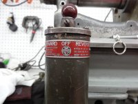
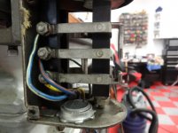
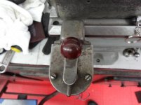
I am rebuilding a South Bend 9" lathe and it has the original GE 110v motor and a Furnas forward-reverse switch that I want to keep. I have no idea how to wire the two together. I was hoping someone on here can help. Here are some pics of the motor and switch. I'll probably have to do 2 posts as there are 9 pics I think.

Thanks,

Jim
 

Attachments

  • South bend motor wiring 012.JPG
    South bend motor wiring 012.JPG
    138.2 KB · Views: 49
  • South bend motor wiring 011.JPG
    South bend motor wiring 011.JPG
    144.6 KB · Views: 41
  • South bend motor wiring 010.jpg
    South bend motor wiring 010.jpg
    34 KB · Views: 40
  • South bend motor wiring 009.jpg
    South bend motor wiring 009.jpg
    44.2 KB · Views: 55
  • South bend motor wiring 008.JPG
    South bend motor wiring 008.JPG
    144.5 KB · Views: 41
  • South bend motor wiring 007.JPG
    South bend motor wiring 007.JPG
    126.5 KB · Views: 202
  • South bend motor wiring 006.jpg
    South bend motor wiring 006.jpg
    39.8 KB · Views: 40
To avoid these ads, REGISTER NOW!
OP
J

jims09build

Well-known member
Joined
Nov 11, 2009
Messages
102
The rest of the pics
 

Attachments

  • South bend motor wiring 005.jpg
    South bend motor wiring 005.jpg
    37.5 KB · Views: 34
  • South bend motor wiring 004.jpg
    South bend motor wiring 004.jpg
    33.7 KB · Views: 23

PRH44

Well-known member
Joined
Dec 25, 2009
Messages
563
Location
Indiana
You have is a split phase motor it has two windings. One winding is wired to the terminals 2 and 3 from the rear. The two wires that are loose are the yellow and red. It appears the markings may have come off. But that's OK they are the winding that gets reversed so it doesn't really matter. Use the split phase wiring diagram below
RS1A_diagram.jpg


Connect as follows
120 volt
Hot=2
Neutral =6
Motor (2) = 1
Motor (3)= 5
Motor red= 3
Motor yellow = 4

The terminals are looking from the this view. You can change direction by swapping the yellow and red on the switch Terminals 1,3,5 top to bottom on left and 2,4,6, top to bottom on right side.

attachment.php
 
Last edited:

PRH44

Well-known member
Joined
Dec 25, 2009
Messages
563
Location
Indiana
Do you know What year your lathe was built? Be very careful with those short wires
 
Last edited:
OP
J

jims09build

Well-known member
Joined
Nov 11, 2009
Messages
102
You have is a split phase motor it has two windings. One winding is wired to the terminals 2 and 3 from the rear. The two wires that are loose are the yellow and red. It appears the markings may have come off. But that's OK they are the winding that gets reversed so it doesn't really matter. Use the split phase wiring diagram below
RS1A_diagram.jpg


Connect as follows
120 volt
Hot=2
Neutral =6
Motor (2) = 1
Motor (3)= 5
Motor red= 3
Motor yellow = 4

The terminals are looking from the this view. You can change direction by swapping the yellow and red on the switch Terminals 1,3,5 top to bottom on left and 2,4,6, top to bottom on right side.

attachment.php

Thank you for the very helpful answer!
 
To avoid these ads, REGISTER NOW!
OP
J

jims09build

Well-known member
Joined
Nov 11, 2009
Messages
102
Do you know What year your lathe was built? Be very careful with those short wires

Original paper work I have says purchased new from R.W. Norris in my home town in 1939. Why are you concerned? There is enough wire sticking out that I can get a solder connector on and slide some shrink tube over them.

Thanks,

Jim
 

PRH44

Well-known member
Joined
Dec 25, 2009
Messages
563
Location
Indiana
I was just curious I Have 1958 9" SB. Sounds like you have a good plan on extending the wires. Maybe just stating the obvious but I always get concerned with short wires. I have seen some motors ruined over the years.
Please take care when soldering, sharp edges can work their way through some of the light weight shrink tube. I would throw some tape over the top. Now I am going to use and old school term FRICTION TAPE. Its very tough and we use to final wrap a connection for added protection only, not for insulating. Good luck with the rebuild its a nice machine.
Post some progress photos from time to time. The photos below is how mine looked when I got it.
SANY0956.jpg


SANY0943.jpg


Paul
 

iplayfast

New member
Joined
Dec 7, 2014
Messages
1
I've got a similar problem. I've just bought a southbend 9 lathe, and the wiring was sketchy on it so I decided to replace it. I replaced it in the same way as it was, but only off and reverse work. Forward does the same as off.
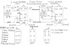
I eventually found someone's wiring diagram that seemed the same as what I got, I've labled wiring diagram with colors so you can follow the panel picture. (Left 120V wiring diagram)

Not all of the posts are connected on the motor panel. does anyone know if that's correct?

Mine southbend's serial number is 25805NBR9 so if you've got one in the same range maybe post a picture of what's in the motor panel (please).

Something else which seemed weird is that post 3 & 4 seem to be connected all the time, no matter what the switch is. This is not at the switch end of the circuit so maybe that is a clue as to what's going on.

Thanks for any help you can give!
 

Attachments

  • Single Phase Reversing Drum Switch.jpg
    Single Phase Reversing Drum Switch.jpg
    113.5 KB · Views: 50
  • motorpanel.jpg
    motorpanel.jpg
    128.5 KB · Views: 29
To avoid these ads, REGISTER NOW!
Top Bottom