To avoid these ads, REGISTER NOW!

wiring an old Marathon motor

Woolfat

Member
Joined
Sep 23, 2018
Messages
18
Location
Don't have one
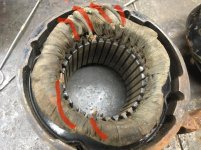
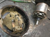
Hello, I have an old Marathon motor ... Marathon Electric Mfg. Co., Wausau, Wis., "OK" 1/4 hp motor that I'm cleaning up and trying to rewire. I'm fairly new to old motor projects but have been learning a bit with some thanks to the help on this forum. To me, and with my limited experience, it looks like a split phase induction motor with a main winding and an start winding with a centrifugal switch. What's got me stumped is there are 6 wires sticking out of the windings. I think other motors I've worked on had 4 wires (2 coming out of each winding). So I'm looking for thoughts on where these wires might go if anyone out there has ideas. What's up with 6 wires? I'll put some pictures on here, the red highlights are to show the 6 wires. Thanks for being here and any help.
 

Attachments

  • IMG_2106.jpg
    IMG_2106.jpg
    153 KB · Views: 20
  • IMG_2108.jpg
    IMG_2108.jpg
    157.2 KB · Views: 20
  • IMG_2109.jpg
    IMG_2109.jpg
    155.7 KB · Views: 17
To avoid these ads, REGISTER NOW!
OP
W

Woolfat

Member
Joined
Sep 23, 2018
Messages
18
Location
Don't have one
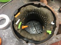
Thanks for the reply, much appreciated. No wiring diagram.. in fact no place for a plate? I've determined connectivity between three pairs of wires and will include a couple more pictures. Thanks again.
So the three pairs of wires would lead me to think it's a 6-pole single-phase AC induction motor. Still scratching my head about how to wire it and where the centrifugal switch fits in the circuit.
 

Attachments

  • IMG_2110.jpg
    IMG_2110.jpg
    153.5 KB · Views: 11
  • IMG_2111.jpg
    IMG_2111.jpg
    159.2 KB · Views: 12
Last edited:

Bert_

Well-known member
Joined
Dec 24, 2016
Messages
9,766
Location
NW Iowa
Thanks for the reply, much appreciated. No wiring diagram.. in fact no place for a plate? I've determined connectivity between three pairs of wires and will include a couple more pictures. Thanks again.
So the three pairs of wires would lead me to think it's a 6-pole single-phase AC induction motor. Still scratching my head about how to wire it and where the centrifugal switch fits in the circuit.

It's 4 pole since it's 1750rpm.

How was it wired before you took it apart?

Did you take resistance readings?
 
To avoid these ads, REGISTER NOW!
OP
W

Woolfat

Member
Joined
Sep 23, 2018
Messages
18
Location
Don't have one
It was not working when I got it - it had been previously taken apart, kind of pushed back together and is missing the 4 long bolts that keep it together. There were fragments of wire attached to what's there now but nothing complete, just a few ratty stubs. Might have been useful, though. Too bad I **** at remembering "before" pics.
When I take resistance readings what will I be looking for? Thanks for your help!
 
Last edited:
OP
W

Woolfat

Member
Joined
Sep 23, 2018
Messages
18
Location
Don't have one
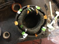
I suspended a piece of steel rod from a thread on a popsicle stick so that the steel was able to swing freely 360 degrees. I rigged up a 12v adapter with a light and some alligator clips to run a small amount of current through the matched pairs of wires. For each pair the rod comes to rest in two perpendicular positions. I marked the locations by color around the edge of the motor housing (orange, white or green). The rod comes to rest at the same spots for the green and white wires but 90 degrees different for the orange wires. It means something :headscrat ummm... Should I assume the orange is the start winding and the green & white are run winding? Why 4 wires for that winding? Thanks for thoughts!
 

Attachments

  • IMG_2115.jpg
    IMG_2115.jpg
    151.8 KB · Views: 8
  • IMG_2116.jpg
    IMG_2116.jpg
    148.1 KB · Views: 8
To avoid these ads, REGISTER NOW!
Top Bottom