To avoid these ads, REGISTER NOW!

Wiring for Walker Turner 900 Series Drill Press

LandsEndSF

New member
Joined
Sep 6, 2023
Messages
4
Location
San Francisco
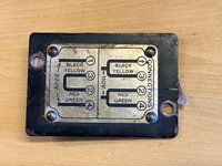
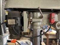
My wife's grandfather gave me his vintage Walker Tuner 900 Series Drill Press when he shut down his shop. It was in good working condition when I took ownership. I've had it in storage for about 8-10 years and would like to put it back in service, but I'm in over my head on the wiring. The plug on it appears to be for 220v 30amp service (though, I'm not certain about that). I have a standard 120v outlet available. The junction box on the drill press has a diagram that shows both 220v and 110v wiring configurations. Neither seem to match what I'm seeing inside. Most of the wires have turned a dingy yellow/brown color, so it's hard to discern what's what. I'm also concerned about the condition of the wires (cracked sheathing) and possible safety issues there.

Any suggestions on how to get this back up and running? Should I hire an electrician? Are there people who specialize in tool/appliance wiring? Any recommendations for someone who might be local to the SF Bay Area? Any help is appreciated.
 

Attachments

  • IMG_1472.jpeg
    IMG_1472.jpeg
    596.7 KB · Views: 47
  • IMG_1473.jpeg
    IMG_1473.jpeg
    657.9 KB · Views: 42
  • IMG_1474.jpeg
    IMG_1474.jpeg
    487.6 KB · Views: 46
To avoid these ads, REGISTER NOW!

RTM

Well-known member
Joined
May 13, 2019
Messages
13,466
Location
SF Bay Area
You might have better luck with a handyman, an electrician might get a bit expensive around here. It seems like I can see a red wire coming out of the body, so it should be connected to the yellow.

The wires connected to the cord should be easy too.

Putting an ohm meter on each pair of wires from the 220v diagram should tell you about shorts inside the motor.

The plug is a NEMA 6-15, which should be 220v.

I don't know if any appliance or tool repair facility in your corner of the world, or mine.
 

alfadan

Well-known member
Joined
Mar 9, 2007
Messages
2,145
Location
Augusta, ks
It can only be wired two ways, so you should be able to determine colors by the way it is wired now. There may be a little color left underneath the wirenuts.

Determine how it is jumpered and you can use colored electric tape to mark them and change it to 120.

My personal opinion, if the insulation cracks, put a good wrap of 33 electrical tape on it, and as long as the frame is grounded, run it. If the insulation in the motor is shot, the whole motor is trash.
 

bmwrd0

Well-known member
Joined
Nov 7, 2010
Messages
5,596
Location
Beaver Fever Oregon
You have two options. You can replace the motor, which is very easy on a W-T 900, or you can check the wiring on the motor that is on there, see how it is wired up (either in series or in parallel, as per the plate), and then procede to wire it the way you would like it.

Neither of these would be too hard, but the first option is easier as long as you have a motor to use, and, as motors burn out and get replaced all the time, it wouldn't be too uncommon to find an unoriginal motor attached. My 900 has a GE motor, and it works great while looking period perfect.

RTM is right, the plug is for 220, and I would bet that it is wired that way. I wouldn't be too hard to mark each wire with painters tape to show the current connections, and then use an ohm meter to check for continuity and too make sure that the diagram is being followed if you are switching to 120vac.
 
OP
L

LandsEndSF

New member
Joined
Sep 6, 2023
Messages
4
Location
San Francisco
Thank you for the suggestions. I'll try one more time to sort out the current state of the wiring. The suggestion to check the wire color beneath the wire nuts is a great call.
 
To avoid these ads, REGISTER NOW!

WillyBoy

Well-known member
Joined
Nov 10, 2021
Messages
658
Location
Genesee valley area of New York state
Faded colors on the older fabric covered wires can be a problem. Walker Turner used pretty much the same convention as Delta for their motor coil wires.

Delta motor connections.jpg

If you have a continuity tester, narrowing down the colors can be easier.
Black and red are opposite ends of one coil.
Yellow and green are opposite ends of the other coil.
The coils are in parallel for what is labelled 110 volts of your junction box cover (typically 120 VAC now).
The coils are in series for what you have labeled 220 volts, (typically 240 VAC now).
Once you mark the wires in some way and disconnect the coils, use the ohmmeter or continuity tester to see which is what.
Red tends to fade to yellowish. Green can look like black. If one wire looks reddish, the other end should be black and so forth.

Good luck with it. Those can be great drill presses and an asset to your shop.
 
OP
L

LandsEndSF

New member
Joined
Sep 6, 2023
Messages
4
Location
San Francisco
Great progress here. I used WillyBoy's suggestion to check continuity and was able to figure out the colors for each wire (I had red/yellow mixed up). I got a new power cable and connected it directly to the motor using the wiring diagram. I bypassed the switch just to see if it would come to life. And it turned right on. Now I need to see if I can figure out how the switch factors into this jumble of wires. I may come back with another question on that. Thank you all for your help.
 

alfadan

Well-known member
Joined
Mar 9, 2007
Messages
2,145
Location
Augusta, ks
Be sure to check that the centrifugal switch operates smoothly with a good "clack" . The motor turns, so it works, but may get sticky not working for a long time. If you ever turn it on and it just hums, turn it off immediately. Have fun!
 

WillyBoy

Well-known member
Joined
Nov 10, 2021
Messages
658
Location
Genesee valley area of New York state
For 120VAC operation, you only need to break one side of the line. Put the switch in series with the black lead going to either the black/yellow connection or the red/green connection. The common (white) can go to the other connection. Connect the ground to a screw on the motor or on the junction box.
 
OP
L

LandsEndSF

New member
Joined
Sep 6, 2023
Messages
4
Location
San Francisco
Thank you to everyone who offered some advice here. The rewiring is complete and the drill press is running again.

Quick summary of how this landed in case it's helpful for anyone in the future...
  • Checked continuity on motor wires to confirm red/green and black/yellow pairs and labeled each.
  • Got some fresh 12AWG power cable and installed new 120VAC plug.
  • Tested motor by connecting black AC wire to red/green pair and white AC wire to black/yellow pair (no switch).
  • Added the switch using a short section of 12AWG cable. Only need to use one side of the switch!
  • Stuffed it all back in the junction box and grounded the power cable to the junction box.
A couple of photos and a wiring diagram below. Thanks again.
 

Attachments

  • IMG_1491.jpeg
    IMG_1491.jpeg
    770.3 KB · Views: 24
  • IMG_1487.jpeg
    IMG_1487.jpeg
    926.7 KB · Views: 25
  • IMG_1490.jpeg
    IMG_1490.jpeg
    612.2 KB · Views: 22
To avoid these ads, REGISTER NOW!
Top Bottom