Does anyone have a suggestion on wire size...I am building an air compressor and using a 5 hp motor that draws 21 amps. My existing 220 power line has a 50 foot run of 10 ga wire and a 20 amp circuit breaker. My plan was to change the breaker to 30 amps and leave the wire as is...any thoughts on whether 10 ga wiring is adequate for this circuit? Also, I noticed that, in the panel, the third wire is hooked to the neutral bar instead of the ground bar...does this make any difference....should I just leave it as is? Thanks in advance for any suggestions or comments...

You are using an out of date browser. It may not display this or other websites correctly.
You should upgrade or use an alternative browser.
You should upgrade or use an alternative browser.
wiring size
- Thread starter lance8614
- Start date
rockwithjason
Well-known member
10ga will work fine for this. a pic of the panel would be worth a 1000 words
RunninOnEmpty
Well-known member
10 gauge is adequate for 21A continuous. If, however, you may upgrade motors by any significant amount later, say to draw 28-30A continuous, then go with 8 gauge now so you're prepared.
Aceman
Well-known member
For a 5HP motor, at a minimum you need #10 THHN and a 35-70 amp breaker.
If your compressor doesn't already have one, you're going to want a starter. Trying to switch a 5HP through the pressure switch isn't going to last, plus if your motor doesn't have an internal thermal overload, you're going to need to install your own.
A starter is the easiest way to fix both of those problems.
And, the ground wire lands on the ground bar, not the neutral bar, if this is a subpanel.
If your compressor doesn't already have one, you're going to want a starter. Trying to switch a 5HP through the pressure switch isn't going to last, plus if your motor doesn't have an internal thermal overload, you're going to need to install your own.
A starter is the easiest way to fix both of those problems.
And, the ground wire lands on the ground bar, not the neutral bar, if this is a subpanel.
wyliesdiesels
Well-known member
^^^ 
Folks, circuits for motors are sized based on NEC FLC NOT motor nameplate FLA...
Folks, circuits for motors are sized based on NEC FLC NOT motor nameplate FLA...
Thanks! I do have a magnetic starter that came with the compressor and it had been running it in a body shop for the last 20 years or so. I will go ahead and move the third wire to the ground bar....why it was on the neutral bar is beyond me.....
pattenp
Well-known member
Thanks! I do have a magnetic starter that came with the compressor and it had been running it in a body shop for the last 20 years or so. I will go ahead and move the third wire to the ground bar....why it was on the neutral bar is beyond me.....
Is the panel that the compressor is wired to a main service panel or a sub-panel? If it's a main service then the neutral and ground are bonded together and the ground on the neutral bar is okay. But if a sub-panel then the neutral and ground are to be isolated.
wyliesdiesels
Well-known member
Thanks! I do have a magnetic starter that came with the compressor and it had been running it in a body shop for the last 20 years or so. I will go ahead and move the third wire to the ground bar....why it was on the neutral bar is beyond me.....
Post a pic of the panel with the cover off.
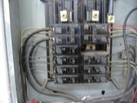
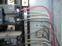
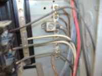
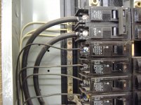
Thanks to everyone who replied. Here are pics of the panel, it is a subpanel in a detached garage/shop. The red and black wires in the upper right are 10 ga for the 220 line. The third white wire from the top is the third wire which is now landing on the neutral bar. The last pic shows the ground bar, which looks to be isolated from the neutral bar. Is it advisable, or even necessary, to move the third wire to the ground bar? The only reason I am asking is that I noticed this arrangement when I took the cover off to install a new 30 amp breaker for my newer larger air compressor. My old smaller compressor worked fine for years and it never occurred to me to see how the circuit was wired. Any comments or suggestions are much appreciated.....Lance
Attachments
RunninOnEmpty
Well-known member
Ground and neutral should only be connected in your main distribution panel and never at a subpanel, junction box, outlet etc.
The reason for this is mainly to ensure that GFCI and AFCI circuits work properly but also simply because the neutral line has a lot of current flowing over it and is essentially more likely to develop a fault that could shock you as a result. Because ground is not normally involved in the current path of your devices, it is far more likely to stay at a lower voltage than neutral in the event of a fault. In all honestly if you don't have GFCI or AFCI, it should work and it is not LIKELY to cause harm to you, but there is no benefit to having it installed incorrectly.
If you have a ground wire going to the neutral line in your subpanel then yes, do move it to ground. If it is supposed to be a ground wire. Some outlets have all 4 wires going to them and would really have a neutral even with 240v and that's fine. Such outlets would also have a ground which is separate from the neutral until it reaches the main distribution panel.
This isn't really a definitive answer as I don't see any info about how the compressor/outlet are wired on the other side. But in general, again, keep your grounds and neutrals separate in subpanels.
The reason for this is mainly to ensure that GFCI and AFCI circuits work properly but also simply because the neutral line has a lot of current flowing over it and is essentially more likely to develop a fault that could shock you as a result. Because ground is not normally involved in the current path of your devices, it is far more likely to stay at a lower voltage than neutral in the event of a fault. In all honestly if you don't have GFCI or AFCI, it should work and it is not LIKELY to cause harm to you, but there is no benefit to having it installed incorrectly.
If you have a ground wire going to the neutral line in your subpanel then yes, do move it to ground. If it is supposed to be a ground wire. Some outlets have all 4 wires going to them and would really have a neutral even with 240v and that's fine. Such outlets would also have a ground which is separate from the neutral until it reaches the main distribution panel.
This isn't really a definitive answer as I don't see any info about how the compressor/outlet are wired on the other side. But in general, again, keep your grounds and neutrals separate in subpanels.
Last edited:
pattenp
Well-known member
Yep, that's a sub-panel and the grounds and neutrals should be separate. Also I may be seeing this wrong but the feeding supply to the panel looks like #2 aluminum going to a 100A breaker. If the wire is #2 AL then the breaker should be no larger than a 90A per the NEC. Not that it's a real safety issue using the 100A breaker. If the wire is copper then never mind.
wyliesdiesels
Well-known member
Pics are really blurry. Can u post some better pics?
Looks like u may have a 4-wire feed but i cant tell if u have a wire going to the ground bar. Is the feeder 3 or 4 wire?
Also looks like u have a backfed main breaker but i cant tell if it has a retainer screw or retention kit...
Can u focus the pics?
Looks like u may have a 4-wire feed but i cant tell if u have a wire going to the ground bar. Is the feeder 3 or 4 wire?
Also looks like u have a backfed main breaker but i cant tell if it has a retainer screw or retention kit...
Can u focus the pics?
Aceman
Well-known member
Ground and neutral should only be connected in your main distribution panel and never at a subpanel, junction box, outlet etc.
The reason for this is mainly to ensure that GFCI and AFCI circuits work properly but also simply because the neutral line has a lot of current flowing over it and is essentially more likely to develop a fault that could shock you as a result. Because ground is not normally involved in the current path of your devices, it is far more likely to stay at a lower voltage than neutral in the event of a fault. In all honestly if you don't have GFCI or AFCI, it should work and it is not LIKELY to cause harm to you, but there is no benefit to having it installed incorrectly.
If you have a ground wire going to the neutral line in your subpanel then yes, do move it to ground. If it is supposed to be a ground wire. Some outlets have all 4 wires going to them and would really have a neutral even with 240v and that's fine. Such outlets would also have a ground which is separate from the neutral until it reaches the main distribution panel.
This isn't really a definitive answer as I don't see any info about how the compressor/outlet are wired on the other side. But in general, again, keep your grounds and neutrals separate in subpanels.
You will do more harm than good making general statements like this about keeping grounds and neutrals separated. It was perfectly legal years ago to do 3 wire feeds(and it still is in Oregon), in which case grounds and neutrals WILL be connected together at the subpanel.
To anyone reading this thread, don't automatically assume anything is wrong with your panel if your grounds and neutrals are combined. If there is any question, start a thread and post some pics with the panel covers removed and I'm sure you'll get the advice you're looking for.
wyliesdiesels
Well-known member
Good eye. I didnt even read his post. Too long.
3-wire feeds were allowed pre 2008 NEC so when i see a 3-wire feed the first thing i ask is when was it wired.
And the primary reason for 4-wire feeds had nothing to do with GFCIs and AFCIs working in relation to a subpanel feed. Hell, GFCIs dont even care about the ground wire. It had to do with neutral current flowing on grounded parrallel metalic pathways...
3-wire feeds were allowed pre 2008 NEC so when i see a 3-wire feed the first thing i ask is when was it wired.
And the primary reason for 4-wire feeds had nothing to do with GFCIs and AFCIs working in relation to a subpanel feed. Hell, GFCIs dont even care about the ground wire. It had to do with neutral current flowing on grounded parrallel metalic pathways...
Last edited:
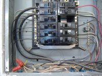
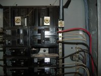
Here are some better pics of the box. Since these were taken I did move the third wire for the 220 circuit (white wire, third from the top, right side) to the ground bar as suggested. But the ground bar and the neutral bar have continuity so I don't know whether this matters or not, the box was installed in 1994, passed inspection at that time, and has been working fine ever since.
Last issue I have is the use of a disconnect box, which I plan to install to be completely safe. Is it better to use a fused or unfused box? My concern is that the 20.6 amp motor I am using (for a Quincy 325 compressor pump) may draw a lot more than 20.6 amps on start up....don't know how many...40? 50? no idea.
If I use a box with time delay fuses are they likely to blow on start-up? I am of course using a mag starter with thermal protection. Any suggestions are much appreciated! Thanks to all who responded. Lance
Last issue I have is the use of a disconnect box, which I plan to install to be completely safe. Is it better to use a fused or unfused box? My concern is that the 20.6 amp motor I am using (for a Quincy 325 compressor pump) may draw a lot more than 20.6 amps on start up....don't know how many...40? 50? no idea.
If I use a box with time delay fuses are they likely to blow on start-up? I am of course using a mag starter with thermal protection. Any suggestions are much appreciated! Thanks to all who responded. Lance
Attachments

wyliesdiesels
Well-known member
Your ground and neutral bars have continuity because pre 2008 code allowed 3-wire feeds...so youre ok with that..
The disconnect should be rated for the same or higher HP rating of the motor. If u have a mag starter, then i wouldnt bother with a fused disconnect...
The disconnect should be rated for the same or higher HP rating of the motor. If u have a mag starter, then i wouldnt bother with a fused disconnect...
Charles (in GA)
Well-known member
It appears that he has a 4 wire feed. The two hots on the upper LH breaker, the bluish looking neutral (prob gray) that lands on the top of the RH neutral bar, and the ground, which is bare aluminum in the large lug on the ground bar. The two neutral bars are connected by the strap across the bottom, and I don't see any bonding screw or strap for the neutral bars to the can, which there should not be anyhow. Looks like a proper 4 wire system to me.
There is continuity between the ground and neutral because they are connected at the main panel.
There is continuity between the ground and neutral because they are connected at the main panel.
wyliesdiesels
Well-known member
It appears that he has a 4 wire feed. The two hots on the upper LH breaker, the bluish looking neutral (prob gray) that lands on the top of the RH neutral bar, and the ground, which is bare aluminum in the large lug on the ground bar. The two neutral bars are connected by the strap across the bottom, and I don't see any bonding screw or strap for the neutral bars to the can, which there should not be anyhow. Looks like a proper 4 wire system to me.
There is continuity between the ground and neutral because they are connected at the main panel.
Funny i couldnt make out the difference in the colors earlier on my phone...i guess it is 4 wire.
Last edited:
The panel is fed w/ SER cable, L,L,N, & bare grounding conductor so the feed is correct for a subpanel, wonder how long ago it was installed (older ITE panel) & if it was required to have a hold down / retainer for the backfed main at the time & if it has one, the retainer on Siemens/ ITE panels are not visible unless the adjacent breaker is removed.
Note: The requirement started with the 1990 edition of the NEC.
Note: The requirement started with the 1990 edition of the NEC.