To avoid these ads, REGISTER NOW!

Wiring up pot lighting with two on/off switches

inline five

Well-known member
Joined
Dec 22, 2014
Messages
125
Location
Raleigh, NC
Guys,

Just wondering. I am replacing my kitchen lighting with a bunch of pot lights. I would like to wire up 8-10 pot lights, but presently there is an on/off switch on both sides of the room.

I was reading about it, and think I need 14/3 for this...correct?

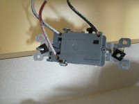
Here is a shot of one of the fixtures.
 

Attachments

  • WIN_20150910_162915.jpg
    WIN_20150910_162915.jpg
    133.6 KB · Views: 78
To avoid these ads, REGISTER NOW!

Shiftless

Well-known member
Joined
Mar 9, 2014
Messages
14,580
Location
East Bay SFO
Guys,

Just wondering. I am replacing my kitchen lighting with a bunch of pot lights. I would like to wire up 8-10 pot lights, but presently there is an on/off switch on both sides of the room.

I was reading about it, and think I need 14/3 for this...correct?

Here is a shot of one of the fixtures.
If the two 3way switches are already in place and operating the current lights, why not just run 14-2 from one of the existing ceiling boxes and daisy chain all the new pot lights together and be done?
Be careful to watch the total amperage draw for all your new lights. If you are on a dedicated 15 amp circuit you'll be fine. If that circuit shares with some other receptacles for example, be double careful not to overload the circuit. If you install LED bulbs in all the cans, I bet your total wattage will be less than your previous set up. If you pop in 60 watt incandescent floods in 10 cans, that might be a problem.
 
OP
I

inline five

Well-known member
Joined
Dec 22, 2014
Messages
125
Location
Raleigh, NC
Thanks guys

Looking to go LED pot lights. So amp draw shouldn't be an issue. Breaker is a 15 amp.

Interesting comment about using 14/2 off the current fixture. I wasn't sure you could do that. That would save cost and reduce complexity of install.
 

DonPowers

Well-known member
Joined
Dec 7, 2014
Messages
4,398
Location
On The Hair At The End Of The Dog's Tail
I agree that 14-2 will also work, however, you need to figure out how they configured the circuit. Does the third wire (traveler) go from switch to switch or are the switches between the lights. Also, where does the power originate, from the light fixture or switch?

Take a look at the various configurations on the link I provided.
 

cybrdyke

Well-known member
Joined
Sep 9, 2014
Messages
3,449
Location
USA
I cant believe people still mess around with the confusion and extra wires of 3-way and 4-way switches.
Power the lights up on black and white, run them thru a Lutron Caseta switch and then stick an additional wireless switch where ever you want it.

CD
 
OP
I

inline five

Well-known member
Joined
Dec 22, 2014
Messages
125
Location
Raleigh, NC
I agree that 14-2 will also work, however, you need to figure out how they configured the circuit. Does the third wire (traveler) go from switch to switch or are the switches between the lights. Also, where does the power originate, from the light fixture or switch?

Take a look at the various configurations on the link I provided.

Oh gosh. I really don't know. Will have to look and get back!
 
OP
I

inline five

Well-known member
Joined
Dec 22, 2014
Messages
125
Location
Raleigh, NC
I cant believe people still mess around with the confusion and extra wires of 3-way and 4-way switches.
Power the lights up on black and white, run them thru a Lutron Caseta switch and then stick an additional wireless switch where ever you want it.

CD

Well the house is over 10 years old, and wasn't that expensive to begin with, so I'm guessing that option wasn't available when it was built...
 

cybrdyke

Well-known member
Joined
Sep 9, 2014
Messages
3,449
Location
USA
Well the house is over 10 years old, and wasn't that expensive to begin with, so I'm guessing that option wasn't available when it was built...

No, definitely not. But it is now. Check it out...it's easy.
CD
 

Shiftless

Well-known member
Joined
Mar 9, 2014
Messages
14,580
Location
East Bay SFO
I agree that 14-2 will also work, however, you need to figure out how they configured the circuit. Does the third wire (traveler) go from switch to switch or are the switches between the lights. Also, where does the power originate, from the light fixture or switch?

Take a look at the various configurations on the link I provided.

Don is right that there are at least 3 different ways to wire up a circuit where 2 switches control a single light or group of lights. However, I believe it won't matter as long as you take the black and white wires off an existing ceiling light and use that pair to feed your line of new pot lights.
Please correct me if I have this wrong.

If you were wiring the room from scratch, it would be more complicated.
 

DonPowers

Well-known member
Joined
Dec 7, 2014
Messages
4,398
Location
On The Hair At The End Of The Dog's Tail
Don is right that there are at least 3 different ways to wire up a circuit where 2 switches control a single light or group of lights. However, I believe it won't matter as long as you take the black and white wires off an existing ceiling light and use that pair to feed your line of new pot lights.
Please correct me if I have this wrong.

If you were wiring the room from scratch, it would be more complicated.

You are correct that only two wires are needed for the lighting fixture to operate.

If power originates in a fixture or the the switch wiring goes through the fixtures, you need to ensure the traveler remains intact and the hot lead is routed to a switch. If the new lighting will not use the existing ceiling boxes, they must be removed as you can't have connection boxes inside a wall or ceiling.

Hope this isn't getting to complicated.
 

justsam

Well-known member
Joined
Aug 20, 2010
Messages
1,268
Location
Penngrove, California
While you have it open, remove that red wire and nip off a bit of the copper. It should not be showing. Most switches will have a "strip" gauge on them. Turn off power first!
 
OP
I

inline five

Well-known member
Joined
Dec 22, 2014
Messages
125
Location
Raleigh, NC
Everything simple always gets complicated!

I was aware you can't have live wires in the ceiling or wall without a cover plate over them.

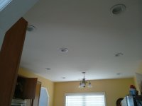
There is only one light fixture in the ceiling and I would be making it into 8-10. So it seems as long as I grab the black and white off the back of it, then wire up each pot in sequence using it, it shouldn't matter which option per the link it's wired as, correct? Otherwise I'm not sure how I'll figure out which is which. It would seem as long as the light has power when I need it (and not) using those wires would still have it work correctly?

The biggest issue will then be planning the wiring sequence in the ceiling with the fewest holes drilled...
 
OP
I

inline five

Well-known member
Joined
Dec 22, 2014
Messages
125
Location
Raleigh, NC
While you have it open, remove that red wire and nip off a bit of the copper. It should not be showing. Most switches will have a "strip" gauge on them. Turn off power first!

You are right, whomever wired it cut it to far back, I'll fix that thanks for noticing!
 
To avoid these ads, REGISTER NOW!

DonPowers

Well-known member
Joined
Dec 7, 2014
Messages
4,398
Location
On The Hair At The End Of The Dog's Tail
Only one light fixture makes it easy to figure out where the power comes from.

I only see three wires at the switch you have open so the power is from the light or other switch. If the other switch only has the 14-3 wire then power is from the light. If its from the light then there will be a bunch of connections in the fixture box. Just use the black and white going to the lamp to feed your new fixtures.
 

Mustang51js

Well-known member
Joined
Jan 24, 2014
Messages
1,734
Location
Haskell nj
I'm trying to understand what you were asking with the 14/3. You only need the 14/3 to go from switch to switch,and it looks like you have that. What kind of existing lights do you have now. You can legally bury a j-box next to the recessed light as long as you can access it by taking the can out,which you should be able to do if your using old work cans. You could also use the can as a j-box if you happen to have a feed through where old light is. All you need is 14/2 to go from light to light. Do you have access to space above or is it a finished room. And where your lights are now, will a new light be going in that spot,just asking because you have the option of just leaving old box in ceiling and using a round blank cover
 
OP
I

inline five

Well-known member
Joined
Dec 22, 2014
Messages
125
Location
Raleigh, NC
I'm trying to understand what you were asking with the 14/3. You only need the 14/3 to go from switch to switch,and it looks like you have that. What kind of existing lights do you have now. You can legally bury a j-box next to the recessed light as long as you can access it by taking the can out,which you should be able to do if your using old work cans. You could also use the can as a j-box if you happen to have a feed through where old light is. All you need is 14/2 to go from light to light. Do you have access to space above or is it a finished room. And where your lights are now, will a new light be going in that spot,just asking because you have the option of just leaving old box in ceiling and using a round blank cover

I'm going to use the hole where the single original light is as a hole for a pot, so no worries there.

I just didn't know you could connect the lights off that single fixture using 14/2. Thinking about it now makes sense though.

This is a first floor kitchen. No access above so I'll have to drill using one of those 4' flex bits...speaking of which what diameter should I get?
 

Shiftless

Well-known member
Joined
Mar 9, 2014
Messages
14,580
Location
East Bay SFO
Use a drill at least an eighth or a quarter bigger than your cable. You don't want a lot of friction drag when you are struggling to pull your NM cable from can to can. I did this exact upgrade years ago. I used the hole left by the old fixture and hooked the old wires to my new can light. But I did have an attic to get easy access.
 
Last edited:
OP
I

inline five

Well-known member
Joined
Dec 22, 2014
Messages
125
Location
Raleigh, NC
OK sorry to keep you guys hanging!

I finished the project (sort of, keep reading).

I added pot lights and didn't end up needing to drill through joists. I could fish the wire to each one. Worked out well except for the insulation running above that I accidentally poked a hole in, but hopefully duct tape sealed it up well enough.

I love all the light. It's great. Now, adding a dimmer. So I have two switches and I've taken a picture of the switch I wish to add the dimmer to. Not quite sure how to follow the lighting diagram.

Obviously the ground goes to ground, but there are two blacks one labeled common on one side and a red(?) going to the other. Oh boy.
 

Attachments

  • WIN_20150918_121514.jpg
    WIN_20150918_121514.jpg
    136.5 KB · Views: 12
  • WIN_20150918_121531.jpg
    WIN_20150918_121531.jpg
    133 KB · Views: 14
  • WIN_20150918_121548.jpg
    WIN_20150918_121548.jpg
    128.6 KB · Views: 13
  • WIN_20150918_121557.jpg
    WIN_20150918_121557.jpg
    131.4 KB · Views: 15

Mustang51js

Well-known member
Joined
Jan 24, 2014
Messages
1,734
Location
Haskell nj
You can only put one dimmer on a 3 way unless they are made specifically for 2 dimmer set up. But if you look at the switch you will have an odd color screw,same with the old switch,as long as that wire is put on same screw the other two don't matter as long as you don't put them on the ground screw lol. Your old switch should have two brass and one black or copper color screw,and the new dimmer should be the same. If you happened to remove old switch and not mark wires then take a pic of the inside of boxes and we can easily tell you which one is which
 

Mustang51js

Well-known member
Joined
Jan 24, 2014
Messages
1,734
Location
Haskell nj
Looking at pics again,the black wire on black screw of old switch goes to the top screw on the dimmer,I'm talking the one opposite side of the ground screw,then the two left over go on the two screws with the one having the paper over it
 
OP
I

inline five

Well-known member
Joined
Dec 22, 2014
Messages
125
Location
Raleigh, NC
Mustang thanks for looking and responding! I thought that was what was supposed to happen but didn't want to blow the lights or cause a fire before doing it. The wiring diagram that came with it wasn't laid out for the non electrician, and I'm not super familiar with the jargon.
 
OP
I

inline five

Well-known member
Joined
Dec 22, 2014
Messages
125
Location
Raleigh, NC
Got it works perfectly thank you everyone!
 

Attachments

  • WIN_20150919_174302.jpg
    WIN_20150919_174302.jpg
    142 KB · Views: 4
Last edited:
To avoid these ads, REGISTER NOW!
Top Bottom