To avoid these ads, REGISTER NOW!

Worthington Air Compressor, need some help

Digital4n6

Well-known member
Joined
Jul 7, 2011
Messages
636
Location
Glen Allen, VA
Have a Worthington air compressor, very old. Maybe from late 1940s to 1960s. Have it connected to a Baldor 5 hp 230v 1ph motor and a Carnegie Steel 70 gallon tank production stamped 1948 as the year.

Stamp states that it is a Worthington compressor, Holyoke plant, "223E 03568" where the model and serial should be. Possibly a "Series E" two stage air cooled reciprocating style compressor. The left side has the larger cylinder and has a very large paper air filter racing towards the back. The right side is the smaller cylinder and is the supply line to the tank (larger copper line towards the right of the compressor) and to to the Square D pressure switch located to the left of the compressor.

The sizings are very difficult to read. Appear to be "4-7/8 x 2-?/8 x 2-?/8" on the second line. Those likely refer to cylinder 1 bore, cylinder 2 bore, and the stroke.

Not sure how the plumbing (if any) should be connected at the top of each as the one that was there before was not original and has broken off. Easy to replace, but not sure if it was correct. One side had a T-fitting (one end was open and sucking in unfiltered air, the other was a compression fitting to 1/4" copper tubing) and the other side had an elbow fitting with a copper tubing running between the two.

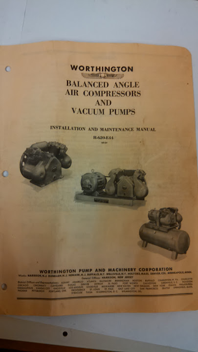
An old picture on a manual located on eBay seemed to picture the holes were simply capped at the top of each and not connected in any manner!

Can anyone help identify the correct plumbing necessary, the missing numbers from the specs, or have access to the parts manual?

Here are some pictures with links to the higher resolution versions. Any help would be appreciated, thanks!

compressor1-sm.jpg


compressor2-sm.jpg


Link to pic of the manual and higher resolution images of above.

http://www.developyour.com/www/garagejournal/compressor_manual.jpg
http://www.developyour.com/www/garagejournal/compressor1.jpg
http://www.developyour.com/www/garagejournal/compressor2.jpg
 
Last edited:
To avoid these ads, REGISTER NOW!

Fixnair

Well-known member
Joined
Jan 5, 2013
Messages
476
Location
Sapulpa OK
The valves in that thing are very troublesome. I don't think you can get repair parts for this guy either. I don't remember the bore & stroke sizes. Good luck with it.
 

cinco

Well-known member
Joined
Jul 25, 2013
Messages
51
Location
Northern CO
Don't know who's running the company these days, but you could always call Worthington themselves. After a bit of digging they were able to identify my boss' pump as a VA2 and they seemed to think they might be able to come up with some basic rebuild stuff. I'm fairly skeptical about that, but we'll see when the time comes.
 

Grigg

Well-known member
Joined
Jul 31, 2010
Messages
268
Location
Lexington, VA
I have a parts manual and installation/maintenance manual at work from a similar Worthington we no longer have, Ours was apparently new in early 50's.

Should be 4.875 and 2.875 bores X 2.125 stroke. At least that's one combination they made that fits the partial info you gave. The parts manual says "series D" with that info and pictures do look the same as yours but I don't see an exact model number.
 
OP
D

Digital4n6

Well-known member
Joined
Jul 7, 2011
Messages
636
Location
Glen Allen, VA
Do you think you could scan and email or postal mail the manual for me? Do you remember what the tops of the cylinders looked like and if there was plumbing running between them?

Sent from my LG-D800 using Tapatalk
 

jeremy v

Banned
Joined
Jul 26, 2011
Messages
784
Doesn't the air for the two-stage function go from one pump to the other through the existing small radiator cooler between the two cylinders? I don't think you need anything else, it looks complete to me. You have the intake and air filter to pump 1 then the line with the cooling radiator to pump 2 and then an air line from pump 2 to the tank.

The broken off stuff probably should just be capped, because I see a complete setup as is.
 
Last edited:

Grigg

Well-known member
Joined
Jul 31, 2010
Messages
268
Location
Lexington, VA
Unfortunately the compressor left during a renovation a year or two before I got here.. they didn't even replace it and later bought an oil free porter cable; basically junk in comparison to a good cast iron compressor.
I remember seeing the compressor years ago but don't recall any details.

See if these pictures help you out any. I suspect you want to look at figure 3 for your plumbing. Otherwise the intercooler is your connection between high an dlow pressure cylinders.
IMG_20140206_084547_263.jpg

IMG_20140206_084516_157.jpg

IMG_20140206_084528_282.jpg


If that looks useful I can see about scanning the rest.
 
OP
D

Digital4n6

Well-known member
Joined
Jul 7, 2011
Messages
636
Location
Glen Allen, VA
Page 4 figure 4 might be the plumbing diagram needed. Can you get a good picture of that one? Really appreciate your help with this!

Sent from my LG-D800 using Tapatalk
 

b-body-bob

Well-known member
Joined
Oct 10, 2011
Messages
1,621
Location
Almost Heaven
It looks based on the pictures that the missing plumbing is for the unloader valve. Here is a link to another Worthington compressor that has the same unloader valve connections all hooked up. The pump is not exactly the same model, but all the important parts are the same as yours.

http://bbs.homeshopmachinist.net/threads/37185-My-quot-new-to-me-quot-not-so-new-Worthington-air-compressor

Be sure to read the whole thread because the posts from weirdscience point out problems in the way it's plumbed.
 
OP
D

Digital4n6

Well-known member
Joined
Jul 7, 2011
Messages
636
Location
Glen Allen, VA
Was reading that thread last night before posting. The plumbing diagram for the recommended setup is gone (image missing) and there was no follow up from the OP after completion. The suggestion seemed to be a closed plumbing line between the two heads on the MS-Paint mock up.

Sent from my LG-D800 using Tapatalk
 
To avoid these ads, REGISTER NOW!
OP
D

Digital4n6

Well-known member
Joined
Jul 7, 2011
Messages
636
Location
Glen Allen, VA
Awesome! That's exactly what was needed!

Looks like for my setup, could just use a copper line between the two "suction unloaders" and not have to plumb it to the trigger valve, or if for super-safety, put a blow-off valve in a t-fitting.
 

jeremy v

Banned
Joined
Jul 26, 2011
Messages
784
Awesome! That's exactly what was needed!

Looks like for my setup, could just use a copper line between the two "suction unloaders" and not have to plumb it to the trigger valve, or if for super-safety, put a blow-off valve in a t-fitting.

So you are setting your compressor up for start-stop duty? That would be like figure 3 of the manual posted. For that setup, you don't need the copper lines at all, you can just cap the two holes off just like the other unit you saw on Ebay. Notice the figure 3 drawing shows no plumbing from either of the suction unloaders. Start-stop duty is how most people set up their compressors.
 

C96

Well-known member
Joined
Nov 30, 2013
Messages
1,251
Very cool compressor
Good luck with the restoration :thumbup:
 
OP
D

Digital4n6

Well-known member
Joined
Jul 7, 2011
Messages
636
Location
Glen Allen, VA
So you are setting your compressor up for start-stop duty? That would be like figure 3 of the manual posted. For that setup, you don't need the copper lines at all, you can just cap the two holes off just like the other unit you saw on Ebay. Notice the figure 3 drawing shows no plumbing from either of the suction unloaders. Start-stop duty is how most people set up their compressors.

After further researching how an "unloader valve" works, looks like you are correct and I should cap them off (but save the suction unloader parts if I ever want to change it to the dual-method in figure 4).

However, not sure that capping them off would be best for the motor since the air trapped would make it more difficult for the compressor to turn over again when the pressure level drops and the motor comes back on, correct?

Shouldn't I setup the system with an unloader valve like in figure 4 even if the connection is not made between the unloader and pressure switch?
 
Last edited:

jeremy v

Banned
Joined
Jul 26, 2011
Messages
784
There are two different things at play here. The unloader valves on the top of each cylinder are most often used when you are running a compressor using a gas engine that stays running at all times. The unloader valves on top of each cylinder remove all compression from the pump whenever there is no demand for air. This allows the gas engine to continue spinning but there is very little fuel use because the pump is basically freewheeling until the demand for air kicks the pumps back in again. Other than running a compressor pump via a gas engine the only other time it is very advantageous to run the pumps in "constant speed" configuration is when you are doing a task that would otherwise require the pump to turn on and off many times an hour. It can save wear on the pump and motor by just leaving it on and letting it freewheel whenever air is not needed. Most compressors (especially the cheaper ones) come set up for "start-stop" configuration only. This is the standard setup where the pump comes on when air is needed and it turns off when pressure has again reached a set level. There is still an unloader of sorts for this type of system, but it works differently.

For a "start-stop" setup, all that matters is making sure that the air pressure in the output line between the tank and the pump is drained of pressure whenever the pump shuts off. This ensures that when the pump starts back up again it will not be trying to start while also fighting air already pressurized in the line. Many electric motors don't have the power to start the pump and fight the line pressure at the same time (if it is anything over about 60psi or so) and even if they could it puts unnecessary wear on the system to run it that way. The dumping of air from the pump to tank air line at the end of a pump cycle is usually handled by the check valve and pressure switch, so nothing is required from the head mounted "suction unloaders". Dumping of the residual air from the pump to tank line is the quick hiss of air that you usually hear when a compressor shuts off.
 

Grigg

Well-known member
Joined
Jul 31, 2010
Messages
268
Location
Lexington, VA
For a "start-stop" setup, all that matters is making sure that the air pressure in the output line between the tank and the pump is drained of pressure whenever the pump shuts off. This ensures that when the pump starts back up again it will not be trying to start while also fighting air already pressurized in the line. Many electric motors don't have the power to start the pump and fight the line pressure at the same time... .

Unloaders can serve this same function of less load so easier starting.
That is extremely common on Quincy brand compressors. The unoladers on them are operated by oil pressure so that when starting (no oil pressure) the compressor isn't compressing. When oil pressure builds the unloaders then allow air to be compressed. They can also be tied to a pressure switch or used for continuous run like a gas engine as mentioned earlier.

If the compressor has unloaders you may as well use them, it can only help.

Grigg
 

Whimsydome

New member
Joined
Apr 20, 2022
Messages
4
This has been the only thread I can find anywhere that has any useful information on this general type of Worthington air compressors. I have a 223U 169 with the same 4.875 and 2.875 bores X 2.125 stroke. I have a gasoline engine running it so I actually need the continuous style set up like Grigg mentioned. I also can't find that manual anywhere and it would be so useful for getting mine set up as I think it's currently set up for start stop which is probably not good. not sure if it was ran this way or if they never finished setting it up. If you could send a copy of that manual that'd be great otherwise just a close up of the figure 2 would help since I can't read it in the other pics.


Whimsydome

New member
Joined
Apr 20, 2022
Messages
4
Thanks for the help Digital4n6. Sourcing parts now. I don't think mine is set up quite right but I'm no expert. It looks like I may have a trigger valve(not sure if it actually is) hooked up right after the larger unloader side then there is like a pressure relief valve( not sure if that's meant to act like a check valve) and then the other side pipes in but from the bottom of the manifold so not the unloader. Then it goes straight into the tank and come out the front side of the tank to a set of pressure regulators I believe. I'm not sure if they are a type of pressure switch. If you have the time I'd appreciate it if you can glance at my pics and see what I mean. If not I understand and I already appreciate your help.

I want to do the Dual controls that way I can use it for both big and small projects. I'm not sure but I feel like I need to hook the two unloaders up to each other (or do they even actually hook up?) I can't tell in the pics if it actually routes into the smaller unloader if its just a bracket. Then I think I would route it to the trigger valve then the pressure switch witch would also be hooked up to the check valve that is hooked up to the manifold. I would also have a stop **** in-between the trigger valve and the pressure switch to switch between continuous and start and stop.
 

Whimsydome

New member
Joined
Apr 20, 2022
Messages
4
Also for anyone checking this thread out here are two more resources. The one pic just shows the ratings at what hp for alot of the models. Mine is similar to model ED. The other is a different manual for similar models but it's slightly different so that may help. Worthington sent these too me so they get the credit for being so helpful and willingly and freely sending this information to me.
 

Attachments

  • DataSheetCV-ED-EY-EU (1).pdf
    345.7 KB · Views: 29
  • InstructionManual-3405-E10B.pdf
    3.6 MB · Views: 26
To avoid these ads, REGISTER NOW!
Top Bottom