
Nothing too exciting - just another LED conversion thread ")
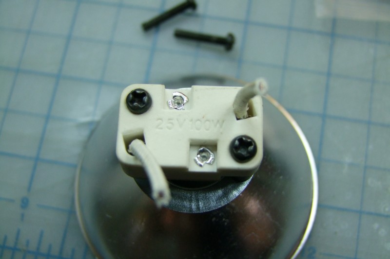
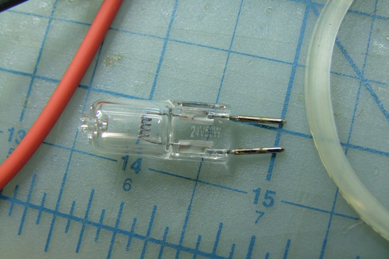
This is how the lamp looked like when it was new:

I used this lamp primarily in my belt sander, and although bright, the coverage was not even/smooth, and of course a little too yellow for my taste (now that I am used to the outstanding Nichia 219), so I decided to convert it to LED (3x Nichia 219's in series, driven at 1.5A by a current-regulated LED driver from TaskLED, being driven by a 12V DC regulated power supply):


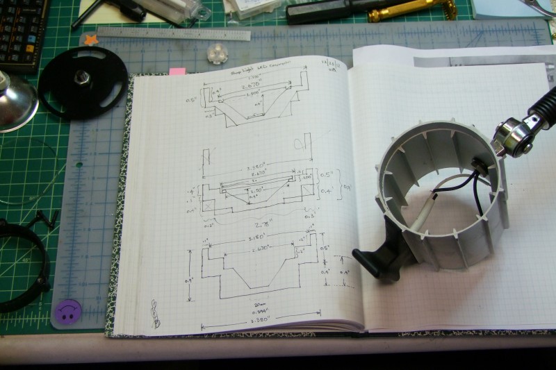
With a rather large outer housing made of Aluminum, I have already a pretty decent way to radiate heat for the LED(s), so I just needed to make a custom heatsink. I feel one should never approach the machines/tools until one has a "rough" idea of what is needed, so after taking some measurements, I made a few paper designs:
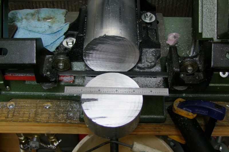
The diameter came at just under 3.5", so I bought a "small" Al rod:

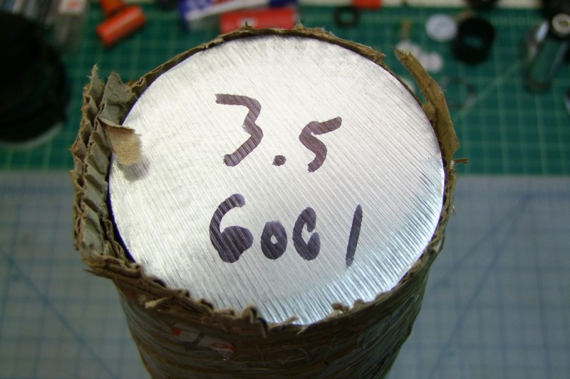

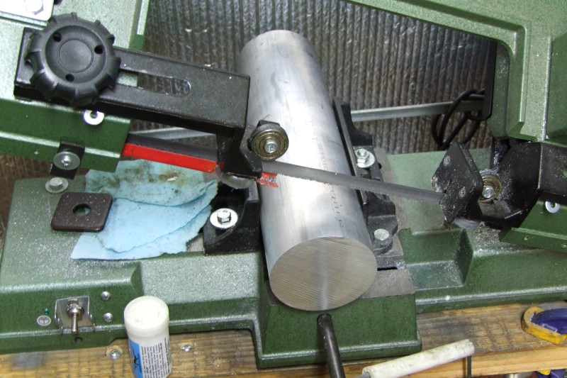
then cut a small chunk:
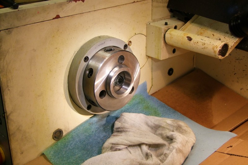
I then ran into a small problem. In my 12x lathe, 99.99% of the time I have an outstanding 6" Set-Tru Bison 6-jaw scroll chuck which is usually calibrated to about 0.0002" TIR, but unfortunately it is a tad small to run this 3.5" dia Al piece, so I had to install the OEM 8" 4-jaw chuck the lathe came with 4-5 years ago.
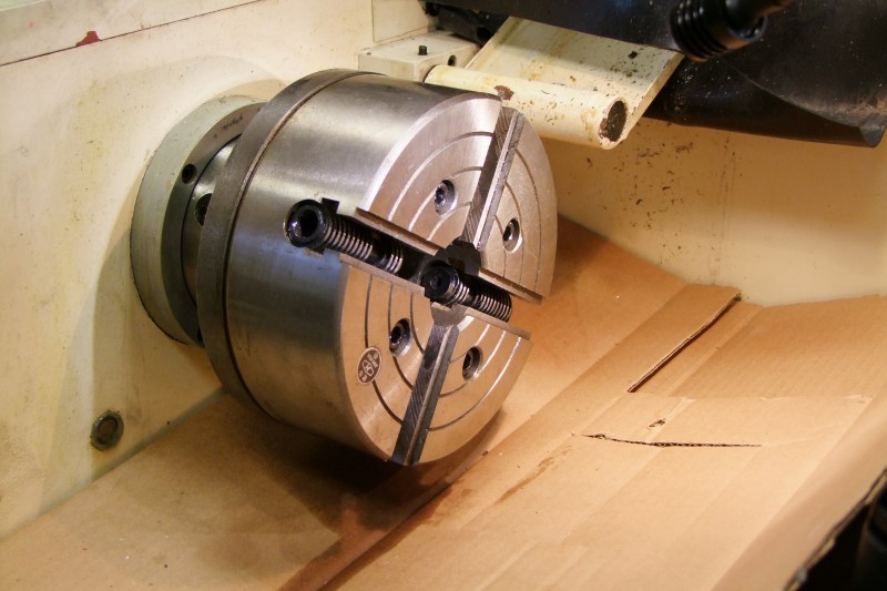
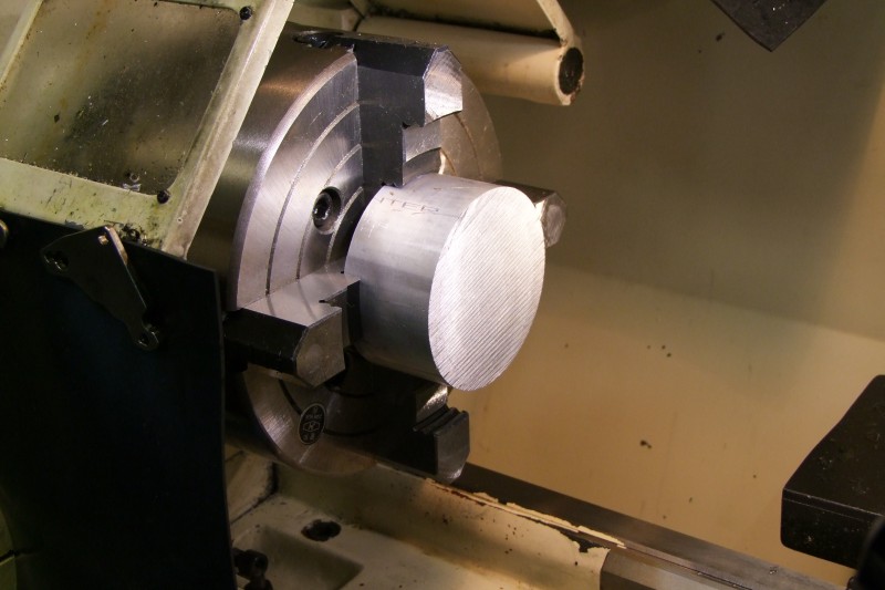
I started by removing the Bison chuck and cleaning everything, and then installing the 8" chuck:
Now I could start work on the custom heatsink. First work on the OD:
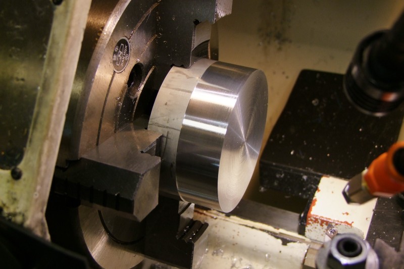
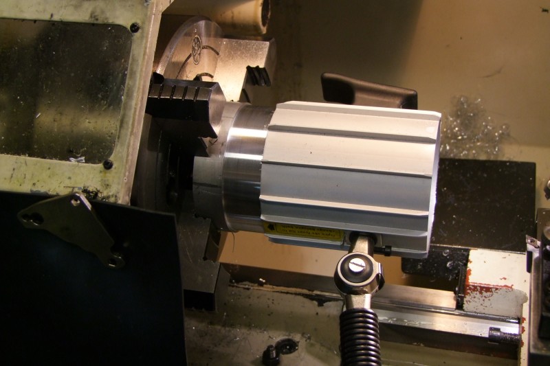
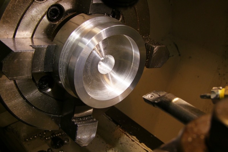
Then work on the area where the LED will sit. Per my paper design above, this is meant to be a floody light, but being that the LED will be inside a "pocket", it will have a slightly more narrow coverage, than if the LED were sitting on the top surface of the heat sink. If you have not tried them yet, these spade drills are the bomb!:
After some more turning and boring, it is starting to look like my paper design:
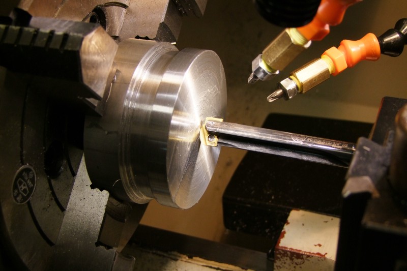
OK, the LED side is complete (still coated with LB2000 lubricant):
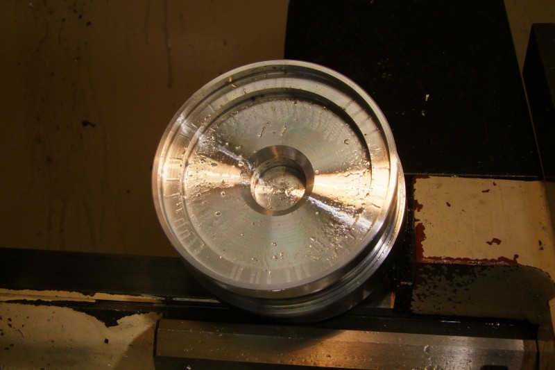
Here I am working on the back side. Besides creating the lip so that it fits inside the Aluminum housing, I am also trying to remove extra material to keep the weight relatively down:

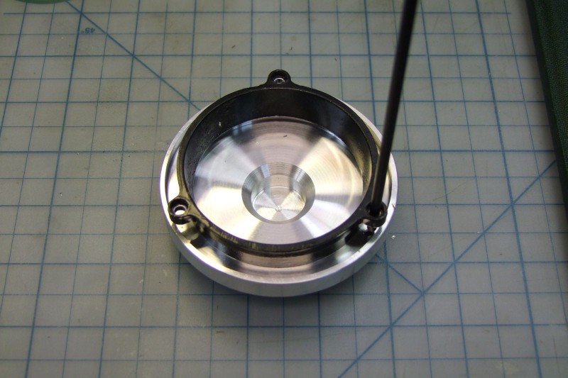
The heatsink got a small nick, but it still looks decent enough - and the sliding fit was spot on:

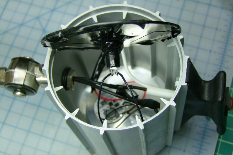
This is how the interior looks like. Note that the switch on top is just a standard SPST switch, which in my case is tied to the positive wire coming from my new 12V DC Regulated power supply:

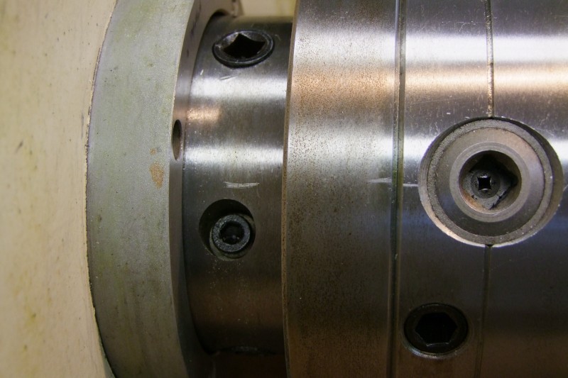
Oh, and by the way, I did put back my Bison chuck on the lathe, which I aligned with scratch marks I made "before" removing it. I still have to re-do the Set-Tru adjustments, but it should be "close" since I am putting it exactly the way it was before:
Since this new LED lamp is meant to be used again in grinder duty, as part of my design, I decided to reuse the back plate (more on that soon), and the front parts that held the glass and gasket. I designed a "shelf" on the heatsink (right above the LEDs), where I put the original gasket, the glass, and then the original retaining ring which slightly compresses the glass against the LED to seal and prevent any rattles. Here I am spot marking where I am going to be drilling and tapping the screws to hold everything in place:
Finalizing this work using my restored Wilton vise with custom soft jaws:

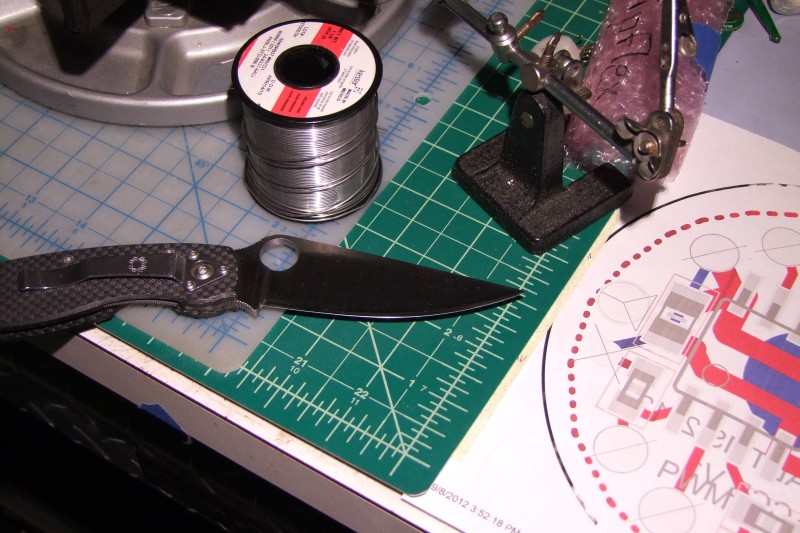
Mark the spot for the two holes for the LED wires:

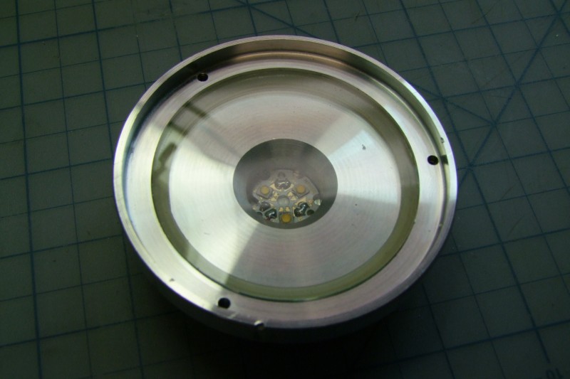
LED set in place (two-part thermal epoxy), here in my electronics work bench:


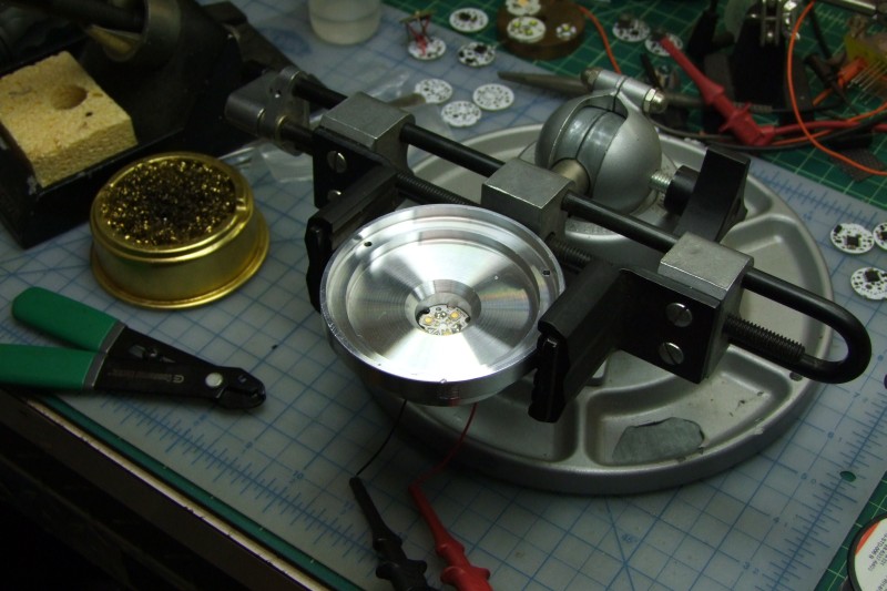
Once the thermal epoxy is set, I of course test the LED's once more:
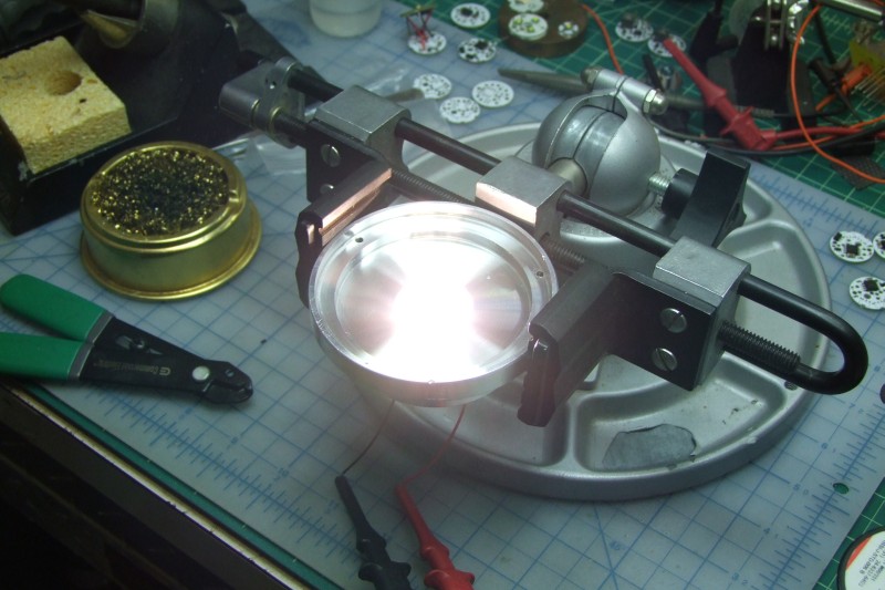
Here is a reference shot with low ambient light (manual exposure), to give you an idea of the smooth, even light coverage (yes, that is a CF M390 Milie):

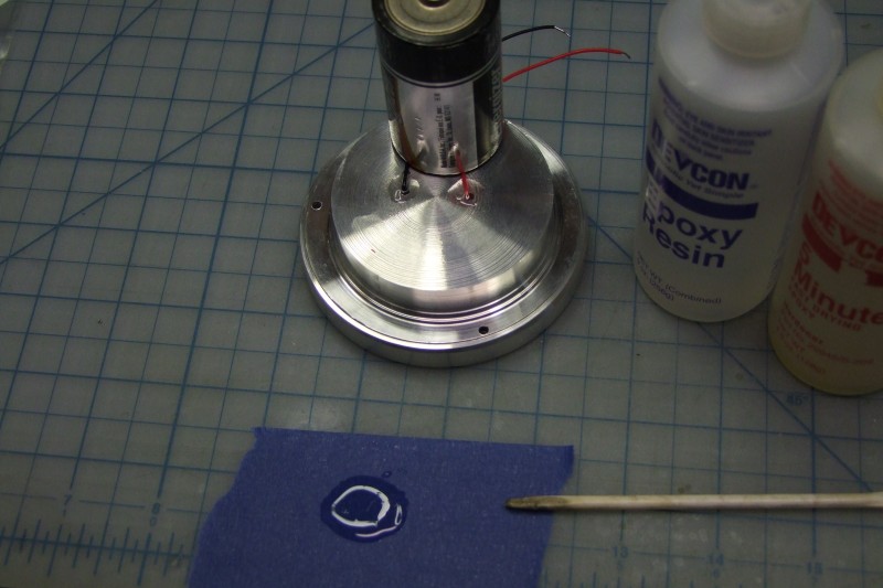
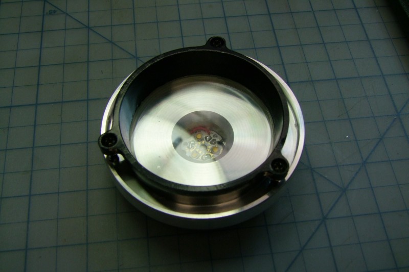
Epoxy wires and seal the wire holes:
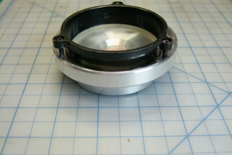
This is how the gasket and glass look like and then with the cover:
Yes, the cover protrudes outward of the housing on purpose - this is to give some protection to the glass in case "stuff" where to get out of hand in the grinder:
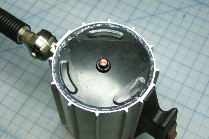
The back cover had 3 holes to provide some air flow for the incandescent light, but I "don't want debris getting inside. Although the LED is sealed on both sides, I don't think the LED driver would "tolerate" metal shorting stuff!, so I just keep things really simple and used electrical tape on both sides. The momentary push bottom is what is used to program/setup/configure the LED driver, and normally will not be used, but having the switch on the "outside" means I don't have to open the back cover to re-configure the LED driver in the future. I used epoxy to make sure the switch stays in place:
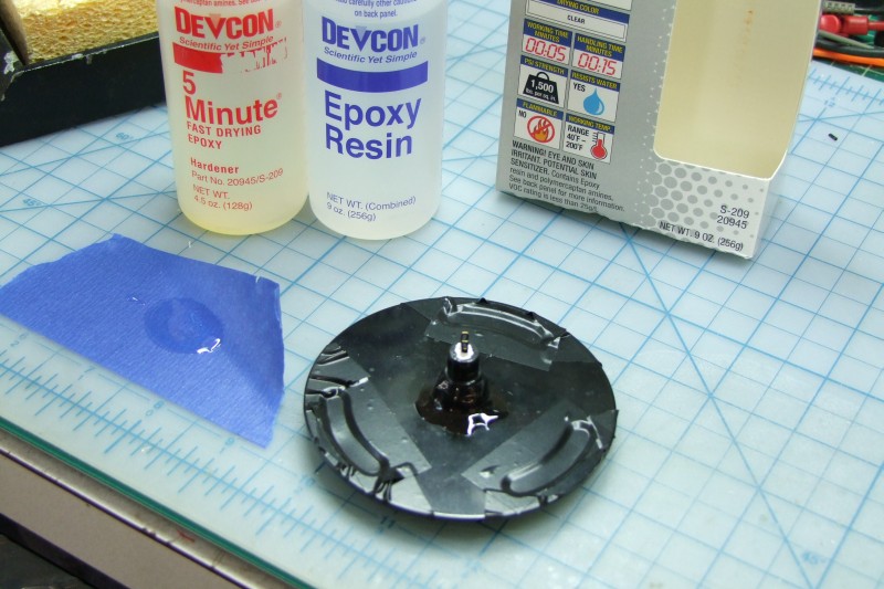
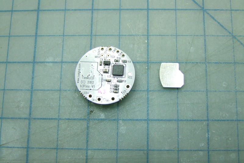
Speaking of the LED driver, this is it: b3Flex. The small Al piece is a custom made piece (by TaskLED) which provides thermal path between the LED driver and the host heatsink:
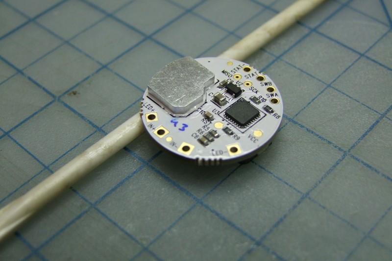
You first use thermal epoxy to "glue" the small heatsink to the LED driver:
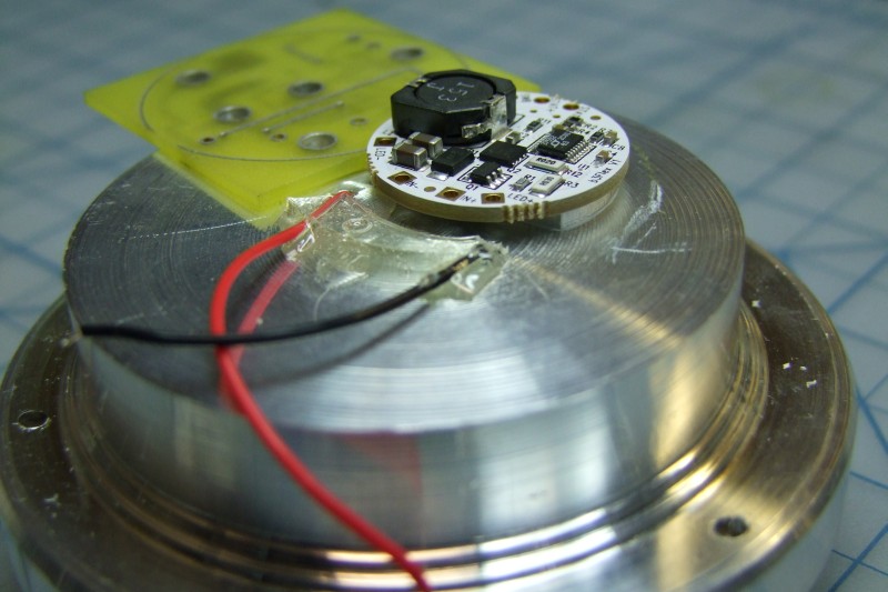
And then use thermal epoxy to "glue" the assembly to the host heatsink:
Then comes the easier part - assembly. First solder the LED driver to the input power (12D VC) and to the rear switch wires:

Then solder the wires to the switch:
Since I don't want this to be permanently closed, I just used hot glue to keep the back plate in place. Not "pretty", but it does the job:
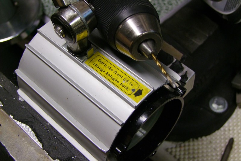
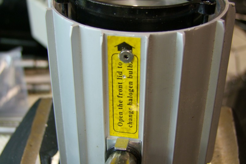
After smearing thermal paste (not epoxy) between the new custom heatsink and the inside of the Aluminum housing, I then drilled and tapped a small screw to make sure things don't move during use:
These two photos here are underexposed on purpose for the comparison (they are much brighter in real life). First, my normal, single LED (Cree XP-G or Nichia 219) look like at 750mA with a small diffusing lens, which I use in my 12x lathe and on my knee mill (camera in manual setting, and yes, I am old enough to need reading glasses):

and here is how the area looks like, at the same height, but from the new lamp - note the great coverage (remember this is under-exposed, at the same manual settings as above):
That is all for now. I think I still have ONE more light in the shop that needs conversion to LED's ........
This is how the lamp looked like when it was new:
I used this lamp primarily in my belt sander, and although bright, the coverage was not even/smooth, and of course a little too yellow for my taste (now that I am used to the outstanding Nichia 219), so I decided to convert it to LED (3x Nichia 219's in series, driven at 1.5A by a current-regulated LED driver from TaskLED, being driven by a 12V DC regulated power supply):
With a rather large outer housing made of Aluminum, I have already a pretty decent way to radiate heat for the LED(s), so I just needed to make a custom heatsink. I feel one should never approach the machines/tools until one has a "rough" idea of what is needed, so after taking some measurements, I made a few paper designs:
The diameter came at just under 3.5", so I bought a "small" Al rod:
then cut a small chunk:
I then ran into a small problem. In my 12x lathe, 99.99% of the time I have an outstanding 6" Set-Tru Bison 6-jaw scroll chuck which is usually calibrated to about 0.0002" TIR, but unfortunately it is a tad small to run this 3.5" dia Al piece, so I had to install the OEM 8" 4-jaw chuck the lathe came with 4-5 years ago.
I started by removing the Bison chuck and cleaning everything, and then installing the 8" chuck:
Now I could start work on the custom heatsink. First work on the OD:
Then work on the area where the LED will sit. Per my paper design above, this is meant to be a floody light, but being that the LED will be inside a "pocket", it will have a slightly more narrow coverage, than if the LED were sitting on the top surface of the heat sink. If you have not tried them yet, these spade drills are the bomb!:
After some more turning and boring, it is starting to look like my paper design:
OK, the LED side is complete (still coated with LB2000 lubricant):
Here I am working on the back side. Besides creating the lip so that it fits inside the Aluminum housing, I am also trying to remove extra material to keep the weight relatively down:
The heatsink got a small nick, but it still looks decent enough - and the sliding fit was spot on:
This is how the interior looks like. Note that the switch on top is just a standard SPST switch, which in my case is tied to the positive wire coming from my new 12V DC Regulated power supply:
Oh, and by the way, I did put back my Bison chuck on the lathe, which I aligned with scratch marks I made "before" removing it. I still have to re-do the Set-Tru adjustments, but it should be "close" since I am putting it exactly the way it was before:
Since this new LED lamp is meant to be used again in grinder duty, as part of my design, I decided to reuse the back plate (more on that soon), and the front parts that held the glass and gasket. I designed a "shelf" on the heatsink (right above the LEDs), where I put the original gasket, the glass, and then the original retaining ring which slightly compresses the glass against the LED to seal and prevent any rattles. Here I am spot marking where I am going to be drilling and tapping the screws to hold everything in place:
Finalizing this work using my restored Wilton vise with custom soft jaws:
Mark the spot for the two holes for the LED wires:
LED set in place (two-part thermal epoxy), here in my electronics work bench:
Once the thermal epoxy is set, I of course test the LED's once more:
Here is a reference shot with low ambient light (manual exposure), to give you an idea of the smooth, even light coverage (yes, that is a CF M390 Milie):
Epoxy wires and seal the wire holes:
This is how the gasket and glass look like and then with the cover:
Yes, the cover protrudes outward of the housing on purpose - this is to give some protection to the glass in case "stuff" where to get out of hand in the grinder:
The back cover had 3 holes to provide some air flow for the incandescent light, but I "don't want debris getting inside. Although the LED is sealed on both sides, I don't think the LED driver would "tolerate" metal shorting stuff!, so I just keep things really simple and used electrical tape on both sides. The momentary push bottom is what is used to program/setup/configure the LED driver, and normally will not be used, but having the switch on the "outside" means I don't have to open the back cover to re-configure the LED driver in the future. I used epoxy to make sure the switch stays in place:
Speaking of the LED driver, this is it: b3Flex. The small Al piece is a custom made piece (by TaskLED) which provides thermal path between the LED driver and the host heatsink:
You first use thermal epoxy to "glue" the small heatsink to the LED driver:
And then use thermal epoxy to "glue" the assembly to the host heatsink:
Then comes the easier part - assembly. First solder the LED driver to the input power (12D VC) and to the rear switch wires:
Then solder the wires to the switch:
Since I don't want this to be permanently closed, I just used hot glue to keep the back plate in place. Not "pretty", but it does the job:
After smearing thermal paste (not epoxy) between the new custom heatsink and the inside of the Aluminum housing, I then drilled and tapped a small screw to make sure things don't move during use:
These two photos here are underexposed on purpose for the comparison (they are much brighter in real life). First, my normal, single LED (Cree XP-G or Nichia 219) look like at 750mA with a small diffusing lens, which I use in my 12x lathe and on my knee mill (camera in manual setting, and yes, I am old enough to need reading glasses):
and here is how the area looks like, at the same height, but from the new lamp - note the great coverage (remember this is under-exposed, at the same manual settings as above):
That is all for now. I think I still have ONE more light in the shop that needs conversion to LED's ........
