To avoid these ads, REGISTER NOW!

ZMotorsports Shop Projects 2.0

ntsqd

Well-known member
Joined
Jan 22, 2005
Messages
1,031
Location
Lower left coast
I never really gave much thought to the mechanism behind vapor lock until we got to talking about it in an email list about 10 years ago. Pulled out some ref books and my calculator. I preceded to become amazed at just how easy it is to create it. With not much of a vacuum the light ends of gasoline can turn into a vapor at 85°-90°F! The worst part is that the stronger your mechanical fuel pump is, the easier it is to create it. Ever since then I've been moving my various carb'd vehicles to electric fuel pumps located at or in the fuel tank.

Who made the Work Horse's engine? Wisconsin maybe? Neat little tractor, anxious to learn more about it when you tear into it.
 
To avoid these ads, REGISTER NOW!
OP
Z

zmotorsports

ALLIANCE MEMBER
Joined
Oct 20, 2009
Messages
21,598
Location
Northern Utah
Mike, all the Land Cruisers where at the annual Solid Axle Summit event.

My daughter and I were in the area the week before. I witnessed one of the most selfish/obnoxious things I’ve ever seen. Coming down Engineer down to Ouray we encounter a full-sized double cab long bed Chevy pulling a 25’ ”adventure trailer”. You know how those switch backs are. He was fully hung up on one and would not accept one bit of help. We told him he had about dozen more heading up, but he would turn around.

You're right, that is pretty selfish. It amazes me that people don't do more research or know much about the trails they are embarking on, especially with all of the information available these days online. We helped a group of guys on big adventure bikes a few years ago that were on Ophir Pass that really had no idea what the trail consisted of, and Ophir Pass is far from hard or even technical. The rocks on the shelf road are the only real problematic issue, but on two wheels, the trail can be brutal going down, let alone up it like these guys were.

A couple of guys in the group welcomed our assistance but there was one guy who was a real *** who blocked the entire trail and didn't seem to care that there were about 8 or so vehicles at the top waiting to go down and 4 at the bottom waiting to go up. When we insisted we help to keep the traffic flowing he proceeded to call us some choice names and almost went fist to cuffs when we walked his bike to the side of the trail so we could all take turns passing. There was an older gentleman in front of us (80-year-old dad of the guy driving) who jumped out of the Jeep and I thought he was going to push the guys bike over the cliff he was so pissed, and maybe push the owner along with it. :ROFLMAO:

Who made the Work Horse's engine? Wisconsin maybe? Neat little tractor, anxious to learn more about it when you tear into it.

The engine in the Wheel Horse is a twin cylinder Kohler.

All of the smaller WheelHorse models were Kohlers. I'd expect the same in the D180 but Mike will confirm I'm sure.

That is correct, the engine is a Kohler opposing twin cylinder. I've read that it is either an 18 or 19 hp Kohler but keep getting conflicting information on which. Either way the guy I purchased it from mentioned that it burned a bit of oil so it will be rebuilt during the restoration process as well..
 
OP
Z

zmotorsports

ALLIANCE MEMBER
Joined
Oct 20, 2009
Messages
21,598
Location
Northern Utah
Hope everyone had a great weekend.

It was a busy one around our place. Our home was volunteered for our annual family reunion so last week I dug a little deeper into my weekly yard maintenance routine. Thursday evening I pressure washed the house, shop and fence and then Friday evening I went through my normal routine of edging, trimming and mowing the lawn.

We were supposed to have around 60-80 people and although that many people on my lawn was messing with my head, I figured it would recover easy enough. Friday evening while the wife and I were sitting on the deck we were looking at the weather predictions and they were now calling for 65% rain and thunderstorms Saturday afternoon into early evening.

I sent out a group text to my siblings letting them know that we hoped the weather held or it would be a rather short party as there was no Plan B. My brother, whom I never thought had a sense of humor, text back stating we could always use the shop with a funny emoji. I told my wife who'd a thunk that my older brother could be funny? :headscrat My wife of course came up with a Plan B, but I wasn't keen on it. She had me move all of the daily drivers from the house garage into the shop so in case we needed to move indoors we at least could fit quite a few people in the house garage. While I was not pleased with this plan I figured it did provide some relief to the yard if needs be.

Saturday morning I moved the vehicles to the shop and went about getting tables and chairs cleaned up and at the ready. The party was supposed to begin @ 5pm and my sister generally is one of the first to arrive with the chicken so it is warm when everyone else arrives. The wife and I were watching the clouds roll in around noon and get darker by the minute. Just after 1pm a few flashes of lightning and a crack of thunder shook the house and the power went out. We just looked at each other and shrugged our shoulders, it was almost comical at this point.

The power proceeded to come back on and go out every 20 or so minutes until about the fourth time it went out, just before 4pm, it never came back on. One of my sisters called to ask if we wanted to come up with another plan and I said I thought we'd be fine as the storm was supposed to be over by around 4:30~ish according to the weather app we were looking at. Although we looked at another app that said it was supposed to continue all evening, but I didn't like what that app was reporting. :bounce:

Another sister text me to ask what it was doing at our place? I typed back "raining", and nothing more. I was to find out later that this one word reply would be a topic of multiple other texts between several siblings that couldn't believe I only replied stating "raining". :ROFLMAO: Goes to show that my siblings really have no idea who I am and that they truly don't know me.


The rain slowed around 4pm but the power had still not come back on. I could see blue sucker holes opening up to the southwest and watching the Dopler on the weather app it didn't seem to have anything else behind it rolling through so the wife and I were feeling confident. About 4:45 I headed out to start setting tables up when my brother arrived with the coolers of ice and drinks.

By 5pm people were arriving and we had blue sky as far as the eyes could see. We had a couple of damp spots on the lawn but most of it was drying nicely so we set up the socker net for our grandson and a couple of ******** games. When people started arriving promptly @ 5pm we set up everyone's lawn chairs on the concrete and ultimately had a great turnout. The wife and I were able to play with our grandson and show him off to many of my family members who have not seen him before. We only had about an hour of direct sunlight, before the sun went behind the shop and the neighbor's shop, then the whole back yard cooled off nicely and it turned out to be a great evening.

Many family members had never been to our home before and in fact, several were asking my wife when first arriving and while setting up the food whose house this was. I was showing a couple of distant cousins the shop around 7:30pm when my son stuck his head into the shop and flipped the light switch saying that the power just came back on, so it had been out for about 4 hours. Upon checking with the neighbors, we found out that the lightning strike around 1pm that shook the house, was in fact a light pole that was struck about a half a mile from our subdivision and blew the top of the pole off and was hanging by the cabling. The last outage was when the crew arrived to replace the pole evidently.

Some people started leaving around 7;30~ish but most of us sat around and visited and a couple dozen didn't leave until after 9pm and well past dark. I had flipped the exterior wall packs on that lit up the back yard and many sat back down and stayed for quite a while, well past dark visiting.

The reunion turned out to be a success and last count I heard was around 60~ish people as a few didn't show. We had a ton of food left over and I don't think anyone went away hungry. To be honest, I was so busy between getting things setup, helping the wife arrange tables and food that I completely forgot to take any pictures.

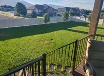
Sunday morning the wife and I sat on the deck enjoying our view and glad that was behind us. Later in the morning I went out and pressure washed the concrete off. My sister then brought her car over for me to give a once over before she headed back to Rock Springs, WY this week.

The weekend seemed to fly by, but in the end it turned out pretty great and weather couldn't have been any better as it cooled off nicely for the reunion compared to the triple digit heat we've been having. Several people had even grabbed jackets as the sun went down. The wife and I could finally sit back and relax but when we were asked about next year I didn't hesitate when I said "hell no." o_O


View from the deck Sunday morning while having our coffee and noticing that the yard survived just fine.
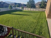
yard10.jpg


yard11.jpg


Thanks for looking.
 
OP
Z

zmotorsports

ALLIANCE MEMBER
Joined
Oct 20, 2009
Messages
21,598
Location
Northern Utah
Every time I see your views I am amazed at how beautiful it is there. While I would not trade my lakes etc in MN for that, it would be a close second for best area.

Thank you. We received a few similar comments about the view we have of the Wasatch Mountains during our reunion Saturday night. People sure liked our view from the backyard, and I have to concur.
 

Mr.zippy

Well-known member
Joined
Apr 27, 2020
Messages
2,225
Location
Wyoming
Mike, we had a family fun day Saturday at Lagoon. Part of the family stayed in Layton, and part at the Lagoon Campground. It did get fairly western right after noon. Around 4:30 on it was pretty good, albeit humid as hell. We did close the park. I managed to be the only one in our group to keep my arms up through the entire rides....which I don't know if that is even worth bragging rights. But I've never ever turned down a nasty scary amusement park ride. Except the 🎡 wheel, those scare the hell out of me.
 
OP
Z

zmotorsports

ALLIANCE MEMBER
Joined
Oct 20, 2009
Messages
21,598
Location
Northern Utah
Mike, we had a family fun day Saturday at Lagoon. Part of the family stayed in Layton, and part at the Lagoon Campground. It did get fairly western right after noon. Around 4:30 on it was pretty good, albeit humid as hell. We did close the park. I managed to be the only one in our group to keep my arms up through the entire rides....which I don't know if that is even worth bragging rights. But I've never ever turned down a nasty scary amusement park ride. Except the 🎡 wheel, those scare the hell out of me.

Yeah, it did turn humid as soon as the rain stopped and the sun came out, luckily it was relatively short lived until the nice cool air arrived.

Glad you had an enjoyable day at Lagoon. It's been many years since we've been there as I don't do amusement park rides. My son used to like going for Halloween as they had "Frightmares" and had the park decorated for Halloween throughout the month of October. We'd usually let him bring a friend and hit the park, but I think it's been close to 15 years since I've been there last.
 
OP
Z

zmotorsports

ALLIANCE MEMBER
Joined
Oct 20, 2009
Messages
21,598
Location
Northern Utah
I was able to finally get back to work in the shop last night and commence the work on my new lathe stand.

Before tying up the fabrication table any longer than necessary, I figured I would attack the smaller items first so I can move through the process quicker once I get to the larger parts.

After measuring the ID of the square tubing, I found some scrap pieces in which to make the threaded bases out of for the adjustable feet to thread into. I currently have 4 adjustable feet on the lathe stand but I would like to add two more to the new stand, which I already had. This will give me a quantity of four (4) under the headstock of the lathe and two (2) at the tailstock end.

I started by rough cutting them down to size.
stand1.jpg

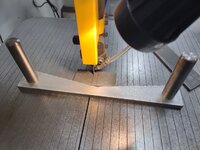
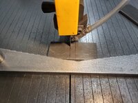
I love how nice this vertical bandsaw cuts and how tight I can keep my parts, within .015"-.020" one from another. They require very little cleanup or "tuning" on the disc sander to make all six exactly the same in size.
stand2.jpg

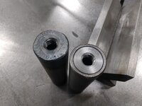
All six cut, corners rounded, edges chamfered and ready to start drilling and tapping the 5/8"-11 threads for the leveling feet.
stand3.jpg

First one down and tested, now to knock out the remaining five.
stand4.jpg

I used my work stop on the mill vise for quick interchange of parts. Spot drill, 3/8" drill, 17/32" drill, chamfer the hole and then power tap to 5/8"-11 thread.
stand5.jpg

All six (6) completed and ready to be welded to the legs once I get to that step. Set aside for now.
stand6.jpg

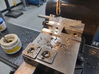
With chips already on the mill, I removed the mill vise and set up one of the .500" plates for drilling the lathe mounting holes. I used a couple of machining squares to get the plate pretty close to parallel with the table.
stand7.jpg

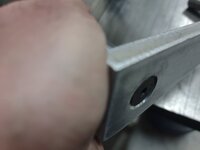
I then setup some work holding clamps and indexed in the plate by tramming the table across the length and using a DTI on the quill. Just by using two machinist squares and feel of my hand on the backside I was able to get within .015". Nothing a couple of light taps with a soft faced mallet couldn't adjust to bring it in dead nuts before tightening the clamps down.
stand8.jpg

Once the plate was setup I setup the edge finder to locate the upper corner as my measurements will come off that corner. I was trying to figure out how to measure the lathe's mounting holes without first unbolting the lathe from its stand, but then I remembered several years ago a fellow forum member emailed me his CAD drawings and sure enough; after digging through my past emails and locating the drawings, he had included the bolt hole dimensions.
stand9.jpg

stand10.jpg


About that time the wife arrived home from work so it was as good as a stopping point as any for the night.

Thanks for looking.
 
OP
Z

zmotorsports

ALLIANCE MEMBER
Joined
Oct 20, 2009
Messages
21,598
Location
Northern Utah
Mike just out of curiosity are your making a version similar to Dan's stand?

Yes, I am. Dan sent me his CAD drawings years ago and I am finally getting around to building a heavier and more customized stand for my 13x40 lathe.

What prompted me to finally get the stick out of my *** and move forward with this was the fact that I picked up a DRO for the lathe about six months ago and want to get it setup so I figured seeing as how I have to move the lathe around to gain access to the rear for the scale installation, I may as well use this opportunity to build the new stand and mount the DRO at the same time.

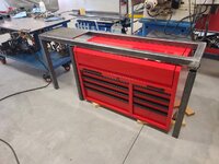
I've had the steel sitting on the shop floor for a while, but I have been looking for the past several months for a toolbox to fill in the gap between the legs. The toolbox Dan used is no longer available, so I've been looking for one for several months. I couldn't bring myself to buy a new one so I've been watching our local online sales website as well as Facebook Marketplace and finally found one about a month ago that I think will work. I will have to modify it slightly but for what I paid for it the fact of making a few cuts doesn't bother me and it's in like new condition.

I also have some sheet 3003 aluminum left over from an old sandrail project so I will use that to cover the side and back of the storage shelf as well as fabricate a door for the storage shelf.

I won't be going to the extent that Dan did using body filler to smooth the welded seams however. I just plan on metal finishing it somewhat smooth then painting it in the textured gray Rustoleum similar to my other workbenches so everything somewhat matches and flows. Dan's lathe stand turned out amazing and I only hope mine turns out half as good.
 

LXCam

ALLIANCE MEMBER
Joined
Apr 23, 2013
Messages
19,357
Location
AZ
Now that's a very cool idea. Mike don't you have a brake on your lathe?. Not that it would stop you from making a stand with the box inserted, I'm interested in how you're going to accommodate it.
 
OP
Z

zmotorsports

ALLIANCE MEMBER
Joined
Oct 20, 2009
Messages
21,598
Location
Northern Utah
Now that's a very cool idea. Mike don't you have a brake on your lathe?. Not that it would stop you from making a stand with the box inserted, I'm interested in how you're going to accommodate it.

Cam, no, my lathe does not have a brake. I have the decelerations slope setup quite steep in the VFD to help compensate but no brake. That is really the only thing that I wish my lathe had and the next one up did have, but my budget wasn't there. To be honest though, in the 10 years I've had this lathe now, I really haven't had any issues where a brake would have been needed. I've learned to thread some things in reverse to compensate and as a safety precaution, which has just taught me another skill to add to my toolbox.
 
OP
Z

zmotorsports

ALLIANCE MEMBER
Joined
Oct 20, 2009
Messages
21,598
Location
Northern Utah
I was able to get the top of the lathe stand framework completed last night.

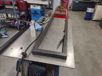
Cutting the lengths to size.
stand11.jpg

For tasks like this I am glad I drilled the fixturing holes in my fabrication table. They come in great for aligning and clamping.......
stand12.jpg

.....to get nice 90-degree corners with no issues. Well, one issue is the end piece is just a tad too long as evident by the slight protrusion at the right.
stand13.jpg

I could have gone over to the disc sander and knocked it down but the Baileigh BS-210 does such a nice job of even the thinnest and most delicate cuts I just took a little bit off with the horizontal bandsaw. Ended up being about .040" and .020" at the other to fine tune the angle and length.
stand14.jpg

After wiping down the tubing and running a DA over the parts it was time to fire up the welder. I haven't done much MIG (GMAW) welding in quite a while.
stand15.jpg

stand16.jpg

After the last of the welds I just left the top frame clamped to the table for the night and closed up the shop.
stand17.jpg


Next will be a little blending of the welds and corners then I can begin on the legs. After speaking with my son, I now know what we want the centerline of the spindle to be so I can calculate leg length.

Thanks for looking.
 
To avoid these ads, REGISTER NOW!
OP
Z

zmotorsports

ALLIANCE MEMBER
Joined
Oct 20, 2009
Messages
21,598
Location
Northern Utah
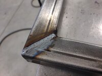
More progress on the lathe stand last night. It took me a bit to figure out a leg length after multiple measurements and calculations but once I finally decided I went ahead and cut the six legs to length while blending the top's corners from previous night's welding.
stand21.jpg

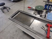
The welds easily blended due to putting a nice chamfer on the edges and keeping the welds smooth and flat. I then test fit the .500" plate into the top.
stand22.jpg

All six (6) legs cut and checked against one another. Have I mentioned just how much I like that Baileigh BS-210 horizontal bandsaw? With relative ease I can match cut to cut within about .015" or less. Here you can see there's not any noticable difference.
stand23.jpg

I went ahead and mocked the top up along with the leg placement for a visual of what I am trying to accomplish.
stand25.jpg

Next, I moved on to cleaning and chamfering the legs as well as used my Dynabrade belt sander to knock the internal seam down the first quarter inch or so of the tubing so I could begin tacking the threaded plates in place.
stand26.jpg

I used a bolt to hold the plates in place then blast tacked them.
stand27.jpg

That was the quitting point for the evening. All six legs have the threaded plates tacked in and ready for final welding.
stand28.jpg


Thanks for looking.
 
OP
Z

zmotorsports

ALLIANCE MEMBER
Joined
Oct 20, 2009
Messages
21,598
Location
Northern Utah
Listen...I'm not here to tell a fella how to design and build a stand, but that lid is going to have some issues opening :LOL: ;)


All kidding aside, looks like it's coming together nicely! That bandsaw definitely makes nice cuts.


What the hell Marc, now ya tell me??? :bounce:

I guess I have to explain ALL my actions because you guys are just too clever and quick for me. ;)

So here goes....... Originally, when I thought about building this lathe stand about 7 or so years ago when I was building my workbenches for the new shop, the HF 44" top box was still available which would match my existing boxes in my workbenches. What I should have done was bought one when I purchased the five bottom boxes for my workbenches back in 2017, but money was getting tight as I had just completed the shop and yard and I was tired of spending money. I figured rather than having to store one, I would just pick one up after the shop was setup and build the lathe stand later. That was the plan anyways. :oops:

However, 7 years later, that matching top box is no longer available. I figured no big deal; I would easily find a used one as they were quite popular. Well, after several months of looking for a good used one to pop up, I really couldn't find that specific one or one even close that I liked without an upper lid. However, I did stumble across this one for the right price a couple of months ago. It is in like new condition as the gentleman purchased for his enclosed trailer several months before, but when he got around to installing it, he discovered it wouldn't work with his overhead cabinets. They wouldn't take it back, so he put in online for sale at what I thought was a good deal, even though it doesn't exactly match what I wanted and was a little taller than I originally intended. As I mentioned in my earlier post, seeing what I paid for it I am less bothered about having to modify it. That top cavity is about 6" or so tall so rather than waste that valuable storage space, I will just trim the leading edge of the lid back which will gain me all that area for storage, such as items in blow molded cases. Things like 1-2-3 and 2-4-6 blocks as well as some of my less used parallels. Things that can be easily accessed from the front, yet less used as other items.

I did find a couple of used boxes that were much, much smaller but seeing that the gain in storage would have been so small, I almost thought it wouldn't have been worth the effort. This box is a bit larger than the one I had originally planned on using but will give me the ability to raise it about an inch and a half to put the lathe spindle centerline closer to match mine and my son's height for comfort. That was one of the main drivers for this lathe stand, followed closely by creating some storage in that wasted space between the end cabinets and lastly to build something out of heavier materials and weight to gain some rigidity. The lathe runs smooth but a bit more mass and rigidity are always a good thing with machining equipment.

This is where things got tricky last night, deciding on an overall length for the legs and therefore the overall height of the stand. I knew how much vertical space I needed for the toolbox, but when I added up all of the material thickness on my sketched drawing, as well as the desired space for the toolbox, I was looking at a lathe spindle centerline at 50 inches. That is a couple inches taller than I want it so rather than put the box on the floor I had to make up about 2 inches somehow.

The toolbox measures 26.5" in height and so I just rounded the opening up to 27.5" in my first iteration for ease of installation. I ended up cutting that down to 27", then I ended up finding some .187" wall 1" square tubing to span across the legs under the toolbox rather than using the same 2"x .120" tubing that I am using for the majority of the stand. Lastly, I opted to sink the top mounting plates flush with the 2" square tubing upper framework rather than on top of it as originally planned and lastly, I sunk the 1/4" threaded plates into the legs rather than outside and using open corner joints for welding. Those trimmed down dimensions netted me just over 2" that I needed to keep the spindle centerline @ 48", up about an inch and a half from what it is currently.

Hope all that makes sense Marc. I actually had to put a bit more thought into this stand that I'm sure it looks and that I had originally planned. I figured I'd just knock it out and where it landed, it landed. However, upon more measurements last night that wasn't the case and I had to get a bit more creative and think everything through much more detailed than I expected.


Before typing all that, I had planned on just saying "I hadn't thought it through Marc", but I would hope you would know me better than that. :unsure:
 
OP
Z

zmotorsports

ALLIANCE MEMBER
Joined
Oct 20, 2009
Messages
21,598
Location
Northern Utah
I knew you had a plan, but if I didn't bust your chops a little on the low hanging fruit, am I even being a good friend?!

I was picking up what you were putting down Marc. :bounce: But, I also figured if you were asking or commenting, others were probably wondering the same thing so I may as well explain myself and get it out there. ;)
 

Duker

Well-known member
Joined
Sep 25, 2010
Messages
10,885
Location
Livingston, TX
What the hell Marc, now ya tell me??? :bounce:

I guess I have to explain ALL my actions because you guys are just too clever and quick for me. ;)
So here goes....... Originally, when I thought about building this lathe stand about 7 or so years ago when I was building my workbenches for the new shop, the HF 44" top box was still available which would match my existing boxes in my workbenches. What I should have done was bought one when I purchased the five bottom boxes for my workbenches back in 2017, but money was getting tight as I had just completed the shop and yard and I was tired of spending money. I figured rather than having to store one, I would just pick one up after the shop was setup and build the lathe stand later. That was the plan anyways. :oops:

However, 7 years later, that matching top box is no longer available. I figured no big deal; I would easily find a used one as they were quite popular. Well, after several months of looking for a good used one to pop up, I really couldn't find that specific one or one even close that I liked without an upper lid. However, I did stumble across this one for the right price a couple of months ago. It is in like new condition as the gentleman purchased for his enclosed trailer several months before, but when he got around to installing it, he discovered it wouldn't work with his overhead cabinets. They wouldn't take it back, so he put in online for sale at what I thought was a good deal, even though it doesn't exactly match what I wanted and was a little taller than I originally intended. As I mentioned in my earlier post, seeing what I paid for it I am less bothered about having to modify it. That top cavity is about 6" or so tall so rather than waste that valuable storage space, I will just trim the leading edge of the lid back which will gain me all that area for storage, such as items in blow molded cases. Things like 1-2-3 and 2-4-6 blocks as well as some of my less used parallels. Things that can be easily accessed from the front, yet less used as other items.
I did find a couple of used boxes that were much, much smaller but seeing that the gain in storage would have been so small, I almost thought it wouldn't have been worth the effort. This box is a bit larger than the one I had originally planned on using but will give me the ability to raise it about an inch and a half to put the lathe spindle centerline closer to match mine and my son's height for comfort. That was one of the main drivers for this lathe stand, followed closely by creating some storage in that wasted space between the end cabinets and lastly to build something out of heavier materials and weight to gain some rigidity. The lathe runs smooth but a bit more mass and rigidity are always a good thing with machining equipment.

This is where things got tricky last night, deciding on an overall length for the legs and therefore the overall height of the stand. I knew how much vertical space I needed for the toolbox, but when I added up all of the material thickness on my sketched drawing, as well as the desired space for the toolbox, I was looking at a lathe spindle centerline at 50 inches. That is a couple inches taller than I want it so rather than put the box on the floor I had to make up about 2 inches somehow.

The toolbox measures 26.5" in height and so I just rounded the opening up to 27.5" in my first iteration for ease of installation. I ended up cutting that down to 27", then I ended up finding some .187" wall 1" square tubing to span across the legs under the toolbox rather than using the same 2"x .120" tubing that I am using for the majority of the stand. Lastly, I opted to sink the top mounting plates flush with the 2" square tubing upper framework rather than on top of it as originally planned and lastly, I sunk the 1/4" threaded plates into the legs rather than outside and using open corner joints for welding. Those trimmed down dimensions netted me just over 2" that I needed to keep the spindle centerline @ 48", up about an inch and a half from what it is currently.

Hope all that makes sense Marc. I actually had to put a bit more thought into this stand that I'm sure it looks and that I had originally planned. I figured I'd just knock it out and where it landed, it landed. However, upon more measurements last night that wasn't the case and I had to get a bit more creative and think everything through much more detailed than I expected.


Before typing all that, I had planned on just saying "I hadn't thought it through Marc", but I would hope you would know me better than that. :unsure:
Not to jump ahead again... BUT.... I am hoping Mike is going to convert that lid to a drawer as I want to do something similar for a cabinet I want to build.... And.... I know Mike is going to work out all of the issues so I can just copy him! :D
 

customh

Well-known member
Joined
Feb 18, 2013
Messages
563
Location
East Bethel, MN
Mike, I am very interested (impressed) in your tool in #10,817. for pushing steel into your bandsaw blade. did you make this? great idea.

See Below.

Moving onto the next "want to do" project, although this one has been on my list since I was in the old shop, so over 8 years now I've wanted to build this but just haven't made the time. I just keep adding other things to the list and this one keeps getting bumped down in priority. Well, as I was looking at my list last night I chose two tasks that I figured I could knock out in one evening.

I have wanted to build a push block for my vertical bandsaw but I remember seeing something like this many years ago and cannot remember for the life of me who manufactured it. Don't quote me but I think it was a DoAll accessory for their vertical bandsaw and had to go off memory as I couldn't even find a picture online. I do remember it having two handles and the center was angled outward slightly, with notches in which the material could nest into while pushing around the saw's table.

I began with a length of aluminum I grabbed from my stock drawer, gave it a wipe with acetone and ran a DA over it.
guide1.jpg

Began the layout and drilled a 3/8" hole just offset enough in the middle to create a radius at the bottom of the V.
guide2.jpg

I dug through my bolt assortment and found a couple of 3/8"-16 flathead countersunk fasteners that screamed for this project. I drilled and countersunk the holes so they would be well below the parent material.
guide3.jpg

Next I cut the V out of the material and knocked the burrs off the edges.
guide3a.jpg

I walked to my round stock drawer and grabbed a few different sizes of round stock to see what felt good in my hands. I settled on 1" diameter but in trying to keep the tool somewhat light, I figured rather than start with solid bar stock that I would use some 1" X .083" tubing and machine a threaded boss for one end and a cap for the other. One threaded boss welded in and the other pressed in awaiting the welding process.
guide4.jpg

With the welding completed, it was back to the lathe to square off the threaded end and put a nice radius on the other. One down and one to go.
guide5.jpg

guide6.jpg

When both handles were complete I applied some Loctite 242 to the threads and installed the handles. Here you can see that the fasteners sit recessed from the parent material which will spend its life sliding against the bandsaw's table.
guide7.jpg

Handles installed. I think I am going to cut some serrations in the "V" side to capture the material being cut but not sure that it is necessary as I'm sure there will be knicks and cuts put in the tool from normal use.
guide8.jpg

Thanks for looking.
 
OP
Z

zmotorsports

ALLIANCE MEMBER
Joined
Oct 20, 2009
Messages
21,598
Location
Northern Utah
Want to send me those CAD drawings? Lol

my brother and I were talking the other night and he goes it seems you are keeping the back half of that one wall empty to the ceiling other than drop downs and flags….what’s up…..

I still eventually want a Mill/lathe and hydrualic press….

Not any solid plans at this point, I just don't need the space filled right now. I originally put all of the fabrication and machining equipment in one quadrant of the shop with the possible plans of installing a mezzanine if/when I get short on storage space. So far that is not needed but I have kept that plan semi-solid, more like Jello. ;)

As for your wish list of tools, all three of those are good choices and really transform a home shop. Like many tools we own as mechanics or fabricators, those are tools that aren't used daily, however, when you need them, you wonder how anyone gets along without them.
 
OP
Z

zmotorsports

ALLIANCE MEMBER
Joined
Oct 20, 2009
Messages
21,598
Location
Northern Utah
So, I have to back up and punt a bit from a previous personal project.

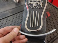
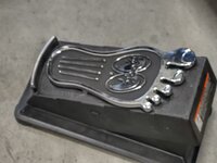
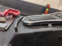
I walked out into the shop Saturday morning with coffee in hand with plans to knock out the welds on the leg's threaded plates and move on to welding the legs to the stand's top. However, I got everything ready on the TIG welder and realized that when I modified my foot pedal a few weeks ago with the Mooneyes gas pedal I did something that I regretted. Not wanting to remove it, because I think it's kinda cool, I went about remedying the issue.


I hadn't used the TIG welder since making the custom modification to my TIG pedal so I didn't realize the issue I had created until I sat down to strike an arc, then the issue was realized instantly. I don't know about others, but I rely on that lip at the end of my TIG pedal greatly to move the pedal around where needed. I use the heel of my shoe to drag the pedal where I need it and it happens almost unconsciously and is like second nature. Well, when I installed the Mooneyes gas pedal it now sits at the same height at that raised lip at the heel of the pedal and now my foot just slips over the lip. That is NOT going to work for me. 🤬
tig11.jpg

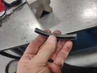
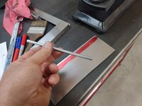
Not handling defeat well, I grabbed the TIG pedal and gave it some thought. I then measured the lip's thickness which was approx. .250" thick. I figured I would fabricate a small riser for that lip to raise it slightly above the added gas pedal. I also grabbed some scrap 14-gauge sheet steel from the metal drop drawer and marked out .500" depth in which to cut.
tig12.jpg

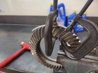
Without wanting to spend a ****-ton of time on this modification I quickly looked around to see what I had within easy reach that was roughly the same radius as the TIG pedal's heel lip. I remembered I still had an old Dana 44 ring gear and it was almost exact. I clamped the O1 drill rod to it and began to form the radius.
tig13.jpg

Matches almost perfect.
tig14.jpg

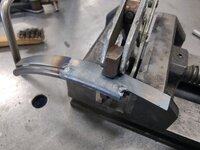
I then welded the two strips of 14-gauge sheet metal to the rod leaving it slightly long on either end.
tig15.jpg

Once welded, I metal finished the piece and cut to length.
tig16.jpg

Ready for installation.
tig17.jpg

The part was just snug enough that it didn't go on easy nor will fall off easily. I applied a bit of glue to the underside and tapped it into place.
tig18.jpg

I also removed the Mooneyes gas pedal and trimmed the threaded bosses down just a bit moving the gas pedal closer to the TIG pedal's surface and also creating a bit taller heel lip.
tig19.jpg

I then proceeded to test it out and it works perfectly. Now I can get back to doing what I started out first thing in the morning. Side job #1 for the day completed.
tig20.jpg


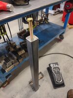
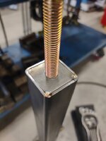
Once being happy with how the TIG pedal turned out and actually fixed my design flaw from the modification, I knocked out the threaded bases for the lathe stand's legs in no time and while they cooled, I could turn my attention to side job #2 for the morning.

For the past 7+ years now I have tolerated my shop's stereo receiver being meh on FM. It has sounded static"y" almost constantly on several of the channels I like to listen to. About two years ago the Optimus receiver that I had at the last shop crapped out and at first thought I contemplated going with something more "modern" and getting with the times.

However, I just loved that old school receiver and me being old school myself I stuck with the same thing and found an exact replacement about the same era as the one I had originally. At first, I thought that this may address my static problem and maybe it was the receiver all along. But nope. The new to me receiver was plagued with the same static issues. I used some speaker wire and mechanics wire to act as a make-shift antenna and it did help quite a lot. Although, I found myself working and as the day or evening went on the static would slowly return and I'd find myself walking to the shop's radio, reaching behind and "tweaking" the wires and it would improve slightly, for a bit. This has been the daily routine for the past 7+ years now and my son just accepted it as normal SOP's for the shop when we'd have the tunes playing.

Well, the past few weeks it has gotten much, much worse and I finally did some research and found a rather inexpensive bipole antenna on Amazon and decided to give it a try. It arrived Friday night and the wife brought it out to me as I was finishing up mowing the lawns. Saturday morning while the legs were cooling after welding I decided to quickly install the antenna and it sounds freakin' amazing.

I cannot believe I tolerated that static for as long as I did. It had become just a standard practice to walk to the radio and move the wires until the static went away and go back to work. I didn't realize just how bad that bothered me until I worked for the entire day Saturday with crystal clear and static free tunes in the shop. It gave the whole shop a completely different "feel" if you can understand.

So once the tunes were fixed, I cranked the stereo up and just enjoyed the day. Work even seemed to flow better as I cut and welded along and didn't really get distracted by anything. Funny how something so simple can get under one's skin so badly and not even be realized until it is remedied.
 
OP
Z

zmotorsports

ALLIANCE MEMBER
Joined
Oct 20, 2009
Messages
21,598
Location
Northern Utah
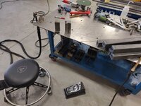
Once the two Saturday morning side jobs were taken care of I began measuring, cutting and welding my way through the lathe stand and progressed nicely.


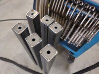
Threaded inserts welded into the legs.
stand31.jpg

All six completed and cooled while I addressed the shop's radio issue.
stand32.jpg

I then stood them on end to ensure they were all the same length.
stand33.jpg

And then started getting them mocked into position for tack welding.
stand34.jpg

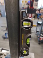
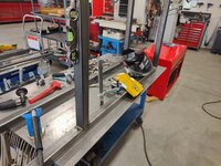
After a couple of tack welds were strategically placed, I double checked the leg's level. It was off slightly, which was pretty much expected. Here I show the tables level as a reference, it's dead nuts level.
stand35.jpg

The leg was slightly off plum with just two solid tacks.
stand36.jpg

I moved to the opposite sides and laid down the beads......
stand37.jpg

....which pulled the leg right into plum. All metal moves somewhat as it is heated and cooled. Knowing how that metal will move, which direction and having a good idea how much is paramount to not fighting small tasks like this and spending time chasing PLS.
stand38.jpg

With the top clamped to the fabrication table, I progressed through the legs one by one checking PLS along the way.
stand39.jpg

stand40.jpg


More to come with next post...
 
OP
Z

zmotorsports

ALLIANCE MEMBER
Joined
Oct 20, 2009
Messages
21,598
Location
Northern Utah
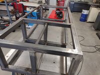
Continuing on with the lathe stand progress.

Progressing through the legs. Tacking, checking PLS, then welding.
stand41.jpg

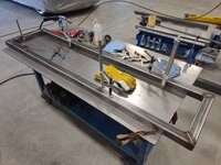
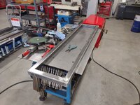
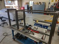
Once all of the legs were welded to the top, I began cutting sections to go between the legs for added strength and rigidity.
stand42.jpg

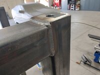
Once the cross bars were installed at the leg's bases, I moved to the cross bars between the legs where the toolbox will reside. I used 1" x .187" tubing that I had on hand here to keep the overall height in check.
stand43.jpg

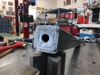
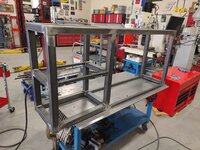
I then thought I'd add some tubing to create a shelf in the storage area of the lathe stand that will be covered by a door similar to what I fabricated for my workbenches.
stand44.jpg

stand45.jpg

As I was making great progress and just listening to tunes and welding, all of a sudden, my wire quite feeding. At first I thought it had burned back to the tip but when I looked it was still protruding with the proper stickout. My next thought was "****, did I just run out of wire?" Sure enough, I opened the side panel and the spool was empty. I don't MIG weld much these days but I at least had a spare spool of .030" wire on hand. So shop side project #3 was in full swing.:bounce:
stand46.jpg

I pulled the last of the .030" wire from the gun's liner and cut it into 3' lengths. I don't like wasting materials and I have found that .030" wire can come in handy for TIG welding small materials at times. The smallest TIG rod I purchase is .045" but the .030" MIG wire is a nice substitute and can be useful so I keep it on hand.
stand47.jpg

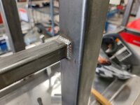
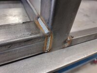
With the new spool of MIG wire installed, it is back to final welding. I then began to knock down a few of the welds and metal finish them. Mainly the ones that will be on the front of the lathe stand for aesthetics, nothing more.
stand48.jpg

The remaining welds will be left untouched as they won't need to be metal finished.
stand49.jpg

That is pretty much where I left off Saturday afternoon.
stand50.jpg

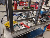
All that is remaining is to add a couple of spreader bars between the 1" square tubing where the toolbox will rest so upon installation it can slide in front to back without dropping between the crossbars and to cut some sheet metal for the lower and middle shelves in the side cabinet and then I can drill the .500" plates for the bolt holes and get them welded in place before painting.

Thanks for looking.
 
To avoid these ads, REGISTER NOW!
Top Bottom